Installation manual - Autec-VLT Automotive Equipment
Installation manual - Autec-VLT Automotive Equipment
Installation manual - Autec-VLT Automotive Equipment
- No tags were found...

Create successful ePaper yourself
Turn your PDF publications into a flip-book with our unique Google optimized e-Paper software.
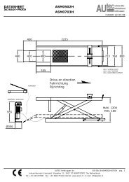
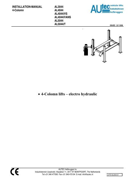
INSTALLATION-MANUAL4-ColomnAL3044AL4044AL4044/VSAL4044/VANSAL5044AL5044/TISSUED 22-7-2008• 4-Colomn lifts – electro hydraulicAUTEC Hefbruggen bvIndustrieterrein IJsselveld, Vlasakker 11, 3417 XT MONTFOORT, The NetherlandsTel:+31 348 477000 Fax:+31 348 475104 E-mail: info@autec.nlen/TD-AL4044-01
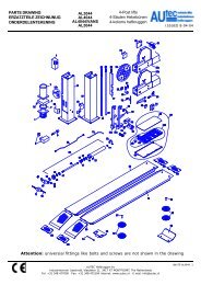
INSTALLATION-MANUAL4-ColomnAL3044AL4044AL4044/VSAL4044/VANSAL5044AL5044/TISSUED 22-7-2008INHOUDSOPGAVEPAG1 Introduction 022 Packing, transport and storage 023 Safety specifications 024 Description of the lift 025 <strong>Installation</strong> 036 Connection to electrical mains 057 Safety checks 058 Goods received report 069 Electrical diagram 071. INTRODUCTIONCAUTIONThis instruction <strong>manual</strong> is intendedfor the assembly personnel who aregoing to carry out the installation ofthe lift.2. PACKING, TRANSPORTAND STORAGEEvery action involving the operation,transportation or unpacking of theequipment must only be done bytrained personnel who have a properknowledge of the lift, and who arefamiliar with the contents of thisoperating <strong>manual</strong>.LIFTING AND MOVING THEPACKING CRATES CONTAININGTHE EQUIPMENTThe wooden crates must be lifted andmoved with the help of a fork lift truck ora lift crane. (Fig. 1)Fig. 1The equipment chosen must becapable of lifting and moving theequipment safely, keeping in mindthe dimensions of the vehicle, theweight, the centre of gravity andprojecting and fragile parts.STORAGEThe packed lift must always the placedin a covered area at a temperaturebetween -10 o C and + 40 o C and mustnot be exposed to direct sunlight.OPENING THE CRATESCheck whether the machine have beendamaged during transportation, andwhether all the components asmentioned in the Packing List arephysically present.REMOVAL OF CRATESThe wood of the crates may be re-used.It is strongly recommendedthat you should first carefully readthe safety instructions.3. SAFETY REGULATIONSThe manufacturer hereby refuses toaccept any responsibility for injury topersons or damage to equipment orproperty if it appears that incorrecthandling of the lift has taken place. Thisinstructions <strong>manual</strong> only describes theoperating- and safety aspects whichpersons who are installing the machineneed to know. In order to understandthe terminology used in this <strong>manual</strong>, it isnecessary that the person performingthe installation work should havespecific experience in industrial work,service, maintenance and repairactivities, and must also possess theability to explain the drawings and thedescriptions contained in this <strong>manual</strong> toother people. At the same time he mustalso be aware of the general andspecific safety regulations which applyin the country where the lift is beinginstalled.4. DESCRIPTION OF THE LIFT(Fig.2)The lift consists of the following :Two platforms and four posts. Thecolumns are fixed to the floor with bolts.The liftingsystem consists of a hydrauliccilinder which converts the horizontalmovement by cabels and pulleys into avertical movement. The lift is controlledby a controlbox mounted on thecontrolpost.Fig.2CONTROL BOX (FIG.3)The controlpanel of the controlboxconsists of the following:11. Mainswitch12. Lifting motion button13. Descend button14. LockingAUTEC Hefbruggen bvIndustrieterrein IJsselveld, Vlasakker 11, 3417 XT MONTFOORT, The NetherlandsTel:+31 348 477000 Fax:+31 348 475104 E-mail: info@autec.nlen/TD-AL4044-02
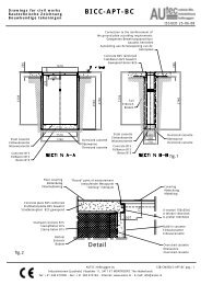
INSTALLATION-MANUAL4-ColomnAL3044AL4044AL4044/VSAL4044/VANSAL5044AL5044/TISSUED 22-7-20085. INSTALLATIONFig.3(Fig. 4), and the rules and regulationsapplicable in the country where the lift isinstalled.In particular, attention should be paid tothe following :• The minimum height from the floor,at the installation location, must be5000 mm• The minimum distance from thewalls must be 1 m.• The minimum working area is 500mm• Adequate room for working• Adequate room for maintenance,access-/ and exit routes.• Position with respect to othermachines• In the neighbourhood of the powersupply point to ensure problem-freeconnection.Fig.5Open the packaging of the columns andplace the columns on the installationlocation. Fit the locking strips in thecolumns. Take care: that this strip runsbehind the strip (1) in the centre of thecolumn (Fig.6).<strong>Installation</strong> may only be doneby persons authorised to do so.BEFORE STARTING INSTALLATION,PLEASE RECHECK ALL THECONTROL POINTS.The lift must be installed in an enclosedspace where weather influences do nothave any effect. The place of installationmust be at a sufficient distance from thestorage locations of paint and wax, andalso rooms where there is a danger ofexplosion.ELECTRICAL POWER SUPPLYPOINT.The client must ensure that there is apower supply point near the installationsite, which satisfies all the applicablelegal requirements (see page 4). If suchpower supply is not available, theinstallation technician will arrange foran emergency cable. The lift shall betested after the emergency powersupply has been dismantled. The clientmust then arrange for a duly qualifiedand recognised installation technician tolay the final wiring.IMPORTANT INSTALLATIONMEASURESThe lift must be installed taking intoaccount the dimensions of other objectsFig.4During the installation nounauthorized persons may bepresent in the safety zone around thelift.• Remove the packaging from thedriving plates.Place the driving tracks on dollies andconvey them to the general location ofinstallation. The driving track with thecabling / hydraulics under the drivingplate must be installed on the same sideas the operating column (fig. 5)Fig.6Place the crossbeams on dollies. Takecare: that the crossbeam with the fusebox is placed on the same side as theoperating column (Fig.7).Fig.7Remove the steel cable from under thedriving plate (Fig.8).Fig.8Lead the cables to the non-operatingside through the crossbeam. The cableAUTEC Hefbruggen bvIndustrieterrein IJsselveld, Vlasakker 11, 3417 XT MONTFOORT, The NetherlandsTel:+31 348 477000 Fax:+31 348 475104 E-mail: info@autec.nlen/TD-AL4044-03
INSTALLATION-MANUAL4-Colomnin the 2nd duct should seen from belowpass through the short section of thecrossbeam. The cable in the 3rd ductshould seen from below pass throughthe long section of the crossbeam(Fig.9). Use for this purpose the stringsupplied.AL3044AL4044AL4044/VSAL4044/VANSAL5044AL5044/TISSUED 22-7-2008Secure now the protective device on thefixed driving plate.Through long part of thecrossbeam (3 e groove)Through short part of thecrossbeam (2 e groove)Short partcrossbeamFig.9Long partcrossbeamFig.10Lead 2 electricity cables from the rearcrossbeam to the front crossbeam. Indoing so lead the cable through thesame passage as the air hose (over theI-profile).Secure the crossbeam to the drivingplates with bolts and turn these handtight(Fig.11).Fig.12Align the riding plates and secure thebolts.Connect the air hose that runs throughthe driveway on both sides to thelocking cylinders.Connect the air hose that emerges fromthe crossbeam on the control side to thecompressed air supply.Now fit the runners in the crossbeams.Take care that the spring rings are fittedto the bolts to secure the blocking plate(Fig.13).Fig.14Connect the electrical wiring to thecontact box on the crossbeam.Place the columns by sliding themagainst the crossbeams.Fit the closed guidance blocks on theexteriors of the crossbeams (Fig.15).Fig.15Now secure the lifting cables in thecolumnFig.11Now lead the steel cables to the side ofthe control unit in the same way throughthe crossbeam as to the non-controlside.Fig.13Fit the open guidance blocks to thecrossbeams. Take care that theassembly bolt is in the centre to allowfor later adjustment. (Fig. 14).FITTING THE CONTROL UNITFit the control unit to the column.Fig.16Connect the cabling to the column asdetailed in diagram Fig.23AUTEC Hefbruggen bvIndustrieterrein IJsselveld, Vlasakker 11, 3417 XT MONTFOORT, The NetherlandsTel:+31 348 477000 Fax:+31 348 475104 E-mail: info@autec.nlen/TD-AL4044-04
INSTALLATION-MANUAL4-ColomnAL3044AL4044AL4044/VSAL4044/VANSAL5044AL5044/TISSUED 22-7-2008Fit the safety switch at the bottom of thecolumn and connect it.Remove the hydraulic hose from underthe platform and lead this together withthe pneumatic hose, the electrical cableof the control unit, the return pipe andany electrical cable for the lightingthrough the flexible hose to the controlcolumn (Fig.17).Fill the oil reservoir.Fig.17Connect the electrical power to thecontrol unitAlign the columns, using if necessaryspacers secured with M12x100.Suspend the safety bars in the column.Fit the catch bars at the tops of thecolumns with double nuts. 1 nut must belocated under the top plate. Caution:the catch bar must be suspended loosein the column (Fig. 18+19)Fig.18Fig.191. Adjust the column cables. Ensurethat the cables are taut when thedriving plates are on the floor.2. Adjust the safety switches (cablebreach/weakness)toapproximately 1.5/ 2 mm (Fig.20)Fig.20Fit the pin that is to serve the switch atthe bottom of the column. Then adjustthe final switch at the bottom of thecolumn (Fig.21).Fig.216. CONNECTING TO THEMAINSWARNINGThe following actions must only becarried out by duly authorisedpersonnel :First check the following points beforeconnecting to the mains:---The electrical system at theworkplace must be protectedaccording to the applicablestandards.The wires must be of the followingsizes : in the case of 400 V theymust be at least 2.5 mm 2 fuse max16A. In the case of 230V 3-phasesupply, the wire size must be atleast 4 mm 2.- The supply cable must be providedwith an earthing wire, and must besuitable for a firm and finalconnection.Connect the power supply cable tothe control cabinet according toFig. 23.Put the main switch in the “1” position.Check the direction of rotation of themotor by pressing the lifting-motionbutton.7. SAFETY CHECKSAfter the complete installation of the lift,the responsible installation engineermust check all the safety arrangementson the lift to check whether they areworking properly.CLEANING OF THE LIFT (Fig. 17)The installation engineer responsiblemust take care to see that the lift whichis installed is delivered to the client in a'squeaky clean' condition.AUTEC Hefbruggen bvIndustrieterrein IJsselveld, Vlasakker 11, 3417 XT MONTFOORT, The NetherlandsTel:+31 348 477000 Fax:+31 348 475104 E-mail: info@autec.nlen/TD-AL4044-05
INSTALLATION-MANUAL4-ColomnFig.228. GOODS RECEIPT REPORTThe concerned installation engineermust prepare a goods receipt reportAL3044AL4044AL4044/VSAL4044/VANSAL5044AL5044/TISSUED 22-7-2008after completion of the installation. Thegoods receipt report must be preparedas carefully as possible. Any complaintsand/or observations of the client willalso be noted in the report under theheading ‘Remarks’. The report must besigned by the responsible installationengineer, and by the client. Theinstallation engineer will deliver thereport to the technical department. Theinstallation engineer must see to it thatthe report are filled-in in time in theservice box.AUTEC Hefbruggen bvIndustrieterrein IJsselveld, Vlasakker 11, 3417 XT MONTFOORT, The NetherlandsTel:+31 348 477000 Fax:+31 348 475104 E-mail: info@autec.nlen/TD-AL4044-06
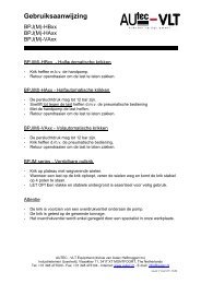
INSTALLATION-MANUAL4-ColomnAL3044AL4044AL4044/VSAL4044/VANSAL5044AL5044/TISSUED 22-7-2008F1 = 2 Amp. FuseS1/S2 = Lift / descendlknopZ1 = BufferS3 = Locking buttonFC1-2-3-4 = MicroswitchFC5 = MicroswitchKM = ContactY1 = Hydr. solenoid valveY2 = Pneum. solenoid valveTemp = Time relais unlockingFig.23AUTEC Hefbruggen bvIndustrieterrein IJsselveld, Vlasakker 11, 3417 XT MONTFOORT, The NetherlandsTel:+31 348 477000 Fax:+31 348 475104 E-mail: info@autec.nlen/TD-AL4044-07
INSTALLATION-MANUAL4-ColomnAL3044AL4044AL4044/VSAL4044/VANSAL5044AL5044/TISSUED 22-7-2008Fig.24AUTEC Hefbruggen bvIndustrieterrein IJsselveld, Vlasakker 11, 3417 XT MONTFOORT, The NetherlandsTel:+31 348 477000 Fax:+31 348 475104 E-mail: info@autec.nlen/TD-AL4044-08