Installation, Operation and Service Manual.pdf - sbs
Installation, Operation and Service Manual.pdf - sbs
Installation, Operation and Service Manual.pdf - sbs
- No tags were found...

You also want an ePaper? Increase the reach of your titles
YUMPU automatically turns print PDFs into web optimized ePapers that Google loves.
System Control<strong>Installation</strong>, <strong>Operation</strong> &<strong>Service</strong> <strong>Manual</strong>WARNINGImproper installation, adjustment, alteration, serviceor maintenance can result in death, injury orproperty damage. Read the <strong>Installation</strong>, <strong>Operation</strong><strong>and</strong> <strong>Service</strong> <strong>Manual</strong> thoroughly before installing orservicing this equipment.<strong>Installation</strong> must be done by a electrician qualifiedin the installation <strong>and</strong> service of control systemsfor heating equipment.InstallerPlease take the time to read <strong>and</strong> underst<strong>and</strong>these instructions prior to any installation.Installer must give a copy of this manual to the owner.OwnerKeep this manual in a safe place in order to provideyour serviceman with necessary information.Roberts-Gordon Europe LimitedUnit A, Kings Hill Business ParkDarlaston Road, WednesburyWest Midl<strong>and</strong>s, WS10 7SH UKTelephone: +44 (0)121 506 7700Fax: +44 (0)121 506 7701<strong>Service</strong> Telephone: +44 (0)121 506 7709<strong>Service</strong> Fax: +44 (0)121 506 7702E-mail: uksales@rg-inc.comE-mail: export@rg-inc.comwww.rg-inc.comwww.combat.co.uk© 2011 Roberts-Gordon Europe Ltd P/N 10091601UK Rev. C 10/11
TABLE OF CONTENTSSECTION 1: Introduction........................................................ 21.1 Safety ........................................................................... 21.2 What is a ROBERTS GORDON ® System Control? ...... 21.3 Electrical Requirements ............................................... 21.4 Check <strong>Installation</strong> Materials ......................................... 2SECTION 2: Specifications .................................................... 42.1 Material Specifications................................................. 42.2 Electrical Specifications ............................................... 42.3 Pump Specifications .................................................... 42.4 Burner Electrical Ratings ............................................. 52.5 Indicator Lights ............................................................ 52.6 Terminal Block Guide................................................... 5SECTION 3: <strong>Installation</strong>.......................................................... 63.1 Preparation .................................................................. 63.2 Installing the System Control Panel ............................. 63.3 Select the External Wiring Diagram for the<strong>Installation</strong>.................................................................... 63.4 System Configuration................................................... 7SECTION 4: Typical External Wiring Diagrams .................... 84.1 Airflow 83 BWLG, Airflow 90 BWTL External WiringDiagram ....................................................................... 84.2 RG30-1 or RG45-1 230 V 1Ø External WiringDiagram ....................................................................... 94.3 RG-30-3 or RG45-3 400V 3 Ø Pump ExternalWiring Diagram .......................................................... 104.4 Thermostat Wire Lengths .......................................... 10SECTION 5: Troubleshooting............................................... 115.1 Sequence of <strong>Operation</strong>.........................................................11SECTION 6: Replacement Parts .......................................... 136.1 Replacement Parts Instructions................................. 14© 2011 Roberts-Gordon Europe LtdAll rights reserved. No part of this work covered by the copyrights herein may be reproducedor copied in any form or by any means - graphic, electronic, or mechanical, includingphotocopying, recording, taping or information storage <strong>and</strong> retrieval systems - without thewritten permission of Roberts-Gordon Europe Ltd.Printed in U.K.
TABLE OF FIGURESFigure 1: Panel Layout .............................................................. 4Figure 2: Terminal Block Guide................................................. 5Figure 3: Mounting Hole Layout................................................ 6Figure 4: System Configuration................................................. 7Figure 5: External Wiring Diagram ROBERTS GORDON ®Airflow 83 BWLG, Airflow 90BWTL 230 V 1 Ø Pump ............................................. 8Figure 6: External Wiring Diagram ROBERTS GORDON ®RG30-1 or RG45-1 230 V 1Ø Pump .......................... 9Figure 7: External Wiring Diagram ROBERTS GORDON ®RG30-3 or RG45-3 400 V 3 Ø Pump ....................... 10Figure 8: System Control Troubleshooting Chart .................... 12Figure 9: System Control Internal Components Diagram........ 13
Product ApprovalROBERTS GORDON ® appliances have been tested <strong>and</strong> CE certified as complying with the essentialrequirements of the Gas Appliance Directive, the Low Voltage Directive, the ElectromagneticCompatibility Directive <strong>and</strong> the Machinery Directive for use on natural gas <strong>and</strong> LPG when installed,commissioned <strong>and</strong> maintained in accordance with these instructions.These instructions refer to appliances designed to operate in the European Union.Appliances designed for other countries (Non-European Union) are available on request.This appliance must be installed in accordance with the local <strong>and</strong> national codes in force <strong>and</strong> usedonly in a sufficiently ventilated space, as specified in these instructions.Before installation, check that the local gas distribution systems, nature of gas <strong>and</strong> pressure, <strong>and</strong>adjustment of the appliance are compatible.1
SYSTEM CONTROL INSTALLATION, OPERATION AND SERVICE MANUALSECTION 1: INTRODUCTION1.1 SafetyYour Safety is Important to Us! Thissymbol is used throughout themanual to notify you of possiblefire, electrical or burn hazards.Please pay special attention whenreading <strong>and</strong> following the warnings.<strong>Installation</strong>, service <strong>and</strong> annual inspection ofcontroller must be done by an electrician qualified inthe installation <strong>and</strong> service of control systems forheating equipment.<strong>Installation</strong>, service <strong>and</strong> annual inspection of heatermust be done by a contractor qualified in theinstallation <strong>and</strong> service of gas or oil fired heatingequipment.Read this manual carefully before installation,operation, or service of this equipment.The appliance must be applied <strong>and</strong> operated underthe general concepts of resonable use.This appliance is not intended for use by persons(including children) with reduced physical, sensory ormental capabilities, or lack of experience <strong>and</strong> knowledge,unless they have been given supervision orinstruction concerning use of the appliance by a personresponsible for their safety.Children should be supervised to ensure that they donot play with the appliance.For optimum heater performance <strong>and</strong> safe heatingconditions, inspect <strong>and</strong> maintain heater(s) beforeevery heating season as necessary. Also, know <strong>and</strong>maintain heater clearances to combustibles, seeheater <strong>Installation</strong>, <strong>Operation</strong> <strong>and</strong> <strong>Service</strong> <strong>Manual</strong> forfurther details. If you require additional manuals, contactyour ROBERTS GORDON ® independent distributoror sales number +44 (0)121 506 7709 or onlineat www.rg-inc.com.1.2 What is a ROBERTS GORDON ® SystemControl?The ROBERTS GORDON ® System Control is anelectronic controller designed for the control ofCORAYVAC ® <strong>and</strong> BLACKHEAT ® (multiburner only)systems.The System Control is capable of giving four zones ofburners' temperature control <strong>and</strong> power. The controlwill also give power output to as many as two pumps,provided that the load is not greater than 20 A <strong>and</strong> 1Ø. For additional electrical specifications see Page 4,Section 2.2.21.3 Electrical RequirementsDANGERElectrical Shock HazardDisconnect electric before service.Controller must be properly grounded to anelectrical source.Failure to follow these instructions canresult in death or electrical shock.Failure to comply with the installation instructions willinvalidate the limited warranty.All wiring must comply with current wiring regulations<strong>and</strong> any local regulations which may apply. Alwaysswitch off the supply to the system control <strong>and</strong> disconnectby removing the plug before removing thetop panel.The system control, burners <strong>and</strong> pump must be electricallygrounded in accordance with local specifications<strong>and</strong> codes.1.4 Check <strong>Installation</strong> MaterialsBefore proceeding with the installation of theROBERTS GORDON ® System Control, check the followingpoints:1.4.1 ThermostatsThe ROBERTS GORDON ® NRG Control or 24Vacthermostats can be used with the System Control.Electronic 24 Vac thermostats <strong>and</strong> mechanical thermostatswith heat anticipator can be used as well.The System Control offers a 24 Vac power supply topower electronic thermostats.Roberts-Gordon Europe Ltd offers a selection of lowvoltage thermostats approved for the use with theSystem Control.The thermostats measure the air temperature in thebuilding. It is important that the thermostat is locatedin an area within the heated zone at occupant level.Do not place thermostat in an area shaded from thelow-intensity, infrared heating system.1.4.2 Electrical <strong>Installation</strong> MaterialsA 230V, 50Hz, 1 ph, 20A power supply to the SystemControl must be installed <strong>and</strong> comply with currentwiring regulations <strong>and</strong> any local regulations whichmay apply.Total load powered by the panel must not exceed20 A. Loads totaling more than 20 A must be
SECTION 1: INTRODUCTIONpowered from an additional power supply circuit bythe use of a load relay package.1.4.3 Pressure SwitchFor CORAYVAC ® <strong>and</strong> BLACKHEAT ® multiburnersystems, a pressure switch (P/N E0007074, includedwith the pump assembly) is required for installationon the inlet of the pump. This switch is required tointerlock the operation of the pump with the controlpanel.CAUTIONProduct Damage HazardPressure switch must be installed on allROBERTS GORDON ® systems to ensuresafety <strong>and</strong> operation.System will not operate without pressureswitch.Failure to follow these instructions can resultin product damage.3
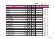
SYSTEM CONTROL INSTALLATION, OPERATION AND SERVICE MANUALSECTION 2: SPECIFICATIONSFIGURE 1: Panel Layout2.1 Material SpecificationsEnclosure Material: MetalWeight: 6.8 lbs (3.08 kg)Dimensions: 10.2" x 11.4" x 2.8"(25.4 x 29.0 x 7.1 cm)Protection: Rating IP202.2 Electrical SpecificationsSupply: 230 V, 50 Hz, 1 Ø, 20 AZone Relay: Single pole 20 A, 230 Vac(resistive)Pump Relay: Single pole 20 A, 230 Vac(resistive)Thermostats: ROBERTS GORDON ® NRGcontrol or low voltage 24Vac(mechanic <strong>and</strong> electronic, also"power stealing")2.3 Pump SpecificationsFull Load CurrentPump Model Watts 230 V 1 Ø 50 Hz 400 V 3 Ø 50 Hz83BWLG 250 2.05 -90BWTL 550 3.3 -RG30-1 750 4.5 -RG45-1 1100 6.4 -RG30-3 750 - 1.77RG45-3 1100 - 2.51For alternate fans, please contact the manufacturer.4
SECTION 2: SPECIFICATIONS2.4 Burner Electrical RatingsCORAYVAC ® burners: 230 V, 50 Hz, 1 Ø 0.1 ABLACKHEAT ® (multiburner only) burners: 230 V, 50Hz, 1 Ø 0.3 A2.5 Indicator LightsSee Page 4, Figure 1.1. LINE POWER, when lit, indicates power issupplied to the panel.2. PUMP POWER 1, when, lit, indicates the relayfor power to pump 1 is energized.3. PUMP POWER 2, when, lit, indicates the relayfor power to pump 2 is energized.4. PRESSURE SWITCH 1, when lit, indicates thatpressure switch 1 is closed. When blinking, indicatesthat the system is in lockout.5. PRESSURE SWITCH 2, when lit, indicates thatpressure switch 2 is closed. When blinking, indicatesthat the system is in lockout.6. ZONE, when lit, indicates which zone relay isenergized.2.6 Terminal Block GuideFigure 2 is a guide to the terminal abbreviations.FIGURE 2: Terminal Block GuidePOWERSUPPLYPUMP 1 ZONE 1BURNERSZONE 2BURNERSZONE 3BURNERSZONE 4BURNERSPUMP 2GROUNDNEUTRALLINENEUTRALLINENEUTRALLINENEUTRALLINENEUTRALLINENEUTRALLINENEUTRALLINEAIR SW 2ZONE 2 RZONE 2 RZONE 2 RZONE 1 RAIR SW 124 VACCOMGN L N L N L N L N L N L N LAIR SW 2ZONE 2 WZONE 2 WZONE 2 WZONE 1 WAIR SW 124 VACCOM5
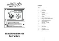
SYSTEM CONTROL INSTALLATION, OPERATION AND SERVICE MANUALSECTION 3: INSTALLATIONDANGERwith pliers one at a time until it is loose. Rotate thecircuit card so that it will line up with the upright cover<strong>and</strong> re-attach to the st<strong>and</strong>offs. The ribbon cable thatconnects the LED status circuit card to the circuitcard assembly will have a twist in it. Use caution notto cause any creases or put any tension to the ribboncable when rotating the circuit card.Electrical Shock HazardDisconnect electric before service.FIGURE 3: Mounting Hole Layout4 x Ø 0.360" (9 mm)Controller must be properly grounded to anelectrical source.Failure to follow these instructions canresult in death or electrical shock.<strong>Installation</strong> of the System Control <strong>and</strong> the associatedexternal electrical wiring must be completed by anelectrician qualified in the installation of controlsystems for heating equipment.3.1 PreparationBefore installing the System Control, observe thefollowing:3.1.1 Ensure that you have a copy of the site layoutfor the project that identifies clearly the separatezones.3.1.2 Read Page 2, Section 1.4 carefully to ensurethe correct installation materials are available.3.2 Installing the System Control Panel3.2.1 Choose a mounting location for the SystemControl. It is advisable to choose a visible locationnear the pump.Do not mount System Control outdoors or in anarea with moisture spray, excessive moisture orhumidity. To avoid damage from possible drips,do not mount controller directly beneath pump.3.2.2 Remove the cover of the System Control byremoving the four securing screws.3.2.3 Place the cover <strong>and</strong> the hardware in a safeplace for refitting after the external wiring connectionshave been made.3.2.4 Position the mounting hole location of the SystemControl per Figure 3.3.2.5 Remove the knockouts required for the conduitentry into the System Control panel. The knockoutsare on the top of the system control case. If theknockouts are required to be on the bottom the casecan be rotated 180°.3.2.6 When the case is rotated 180°, the LED statuscircuit card needs to be rotated so that the LED'smatch the upright cover panel. Remove the LED statuscircuit card by squeezing each st<strong>and</strong>off gently10.0" (254 mm)4.5" (114 mm)3.3 Select the External Wiring Diagram for the<strong>Installation</strong>3.3.1 Use Page 8, Section 4 for the external wiring ofthe burners, thermostats <strong>and</strong> pressure switch.3.3.2 Use the table below to select the correct pumpexternal wiring diagram.Pump Supply Voltage Page Section FigureCORAYVAC ®RG30-1, RG45-1 230 V 1 Ø 50 Hz 9 4 6RG30-3, RG45-3 400 V 3 Ø 50 Hz 10 4 7BLACKHEAT ®Airflow 83 BWLG 230 V 1 Ø 50 Hz 8 4 5Airflow 90 BWTL 230 V 1 Ø 50 Hz 8 4 5The BLACKHEAT ® pumps Airflow 83 BWLG <strong>and</strong> 90BWTL are equipped with thermal overloads.All CORAYVAC ® pumps must use a fan starter kit asindicated on table on the next page. The overloadmust be set to the full load ampere.6
SECTION 3: INSTALLATIONPump Model Full Load Current Overload Range Description Part NumberFan Starter KitS7412KRG30-1 4.5 4 to 61 Overload ZE6 C2351B2 Contactor DILM- 10 4KW,240 V Coil C23483 Enclosure QEWISS GW44207 C2353BFan Starter KitS7411KRG30-3 1.77 1.6 to 2.41 Overload ZE2.4 C2355B2 Contactor DILM- 10 4KW,240 V Coil C23483 Enclosure QEWISS GW44207 C2353BFan Starter KitS7412KRG45-1 6.4 4 to 61 Overload ZE6 C2351B2 Contactor DILM- 10 4KW,240 V Coil C23483 Enclosure QEWISS GW44207 C2353BFan Starter KitS7445KRG45-3 2.51 2.4 to 41 Overload ZE4 C2350B2 Contactor DILM- 10 4KW,240 V Coil C23483 Enclosure QEWISS GW44207 C2353B3.4 System ConfigurationSee Page 7, Figure 4 for details. Below the ribboncable J2 connector, there are six configurable jumpers.They indicate whether the thermostat for eachzone uses an anticipator. If the thermostat for thatassociated zone has an anticipator, then use ajumper to cover both pins for that zone. If the thermostatfor the associated zone does not use an anticipator,then cover the right side pin only.The bottom two jumpers are associated with Pump 2operation. They indicate whether Pump 2 is active<strong>and</strong> which zones are associated with it. Pump 2 canFIGURE 4: System Configurationonly be associated with Zone 3 <strong>and</strong>/or Zone 4. Toenable Pump 2, use a jumper to cover both pins forthe zone(s) that will operate on Pump 2. To disablePump 2, cover only the right side of the pin of zone 3<strong>and</strong> 4.AC POWER IN PUMP 1 ZONE 1 ZONE 2 ZONE 3 ZONE 4 PUMP 2G N L N L N L N L N L N L N LAIRSW124 VACCOMZ1RZ2RZ3RZ4RAIRSW2ANTICIPATORLOAD ENABLEZONE 1ZONE 2ZONE 3ZONE 4ZONE 3ZONE 4PUMP 2OPERATIONENABLEAIRSW124 VACCOMZ1WZ2WZ3WZ4WAIRSW2ANTICIPATORLOAD ENABLEZONE 1ZONE 2ZONE 3ZONE 4ZONE 3ZONE 4PUMP 2OPERATIONENABLEFEATUREENABLEDFEATUREDISABLED7
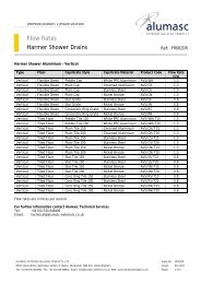
SYSTEM CONTROL INSTALLATION, OPERATION AND SERVICE MANUALSECTION 4: TYPICAL EXTERNAL WIRINGDIAGRAMSDANGERElectrical Shock HazardDisconnect electric before service.More than one disconnect switch may berequired to disconnect electric to the unit.Failure to follow these instructions can resultin death or electrical shock.FIGURE 5: External Wiring Diagram ROBERTS GORDON ® Airflow 83 BWLG,Airflow 90 BWTL 230 V 1 Ø Pump4.1 Airflow 83 BWLG, Airflow 90 BWTL ExternalWiring DiagramThe external wiring diagram below shows the connectionsfor four zones of BLACKHEAT ® multiburnerburners.The zones are connected to a single pump, unlesszone 3 <strong>and</strong>/or zone 4 are selected to function withthe optional pump 2. The external wiring diagrambelow shows connection to an Airflow 83 BWLG, Airflow90 BWTL 230 V 1 Ø pump.4.1.1 External Wiring Connection DetailsIf any of the original wire supplied with the heatermust be replaced, it must be replaced with wiringmaterial having a temperature rating of at least 105°C<strong>and</strong> 600 V.The low voltage circuit must use shielded cable, oneend earthed, the other insulated.Airflow 83 BWLG,Airflow 90 BWTLAll burners must beconnected to Ground(Not shown)Zone 1 Zone 2 Zone 3 Zone 4Airflow 83 BWLG,Airflow 90 BWTLTWO PUMP SYSTEM (optional)Pump 1 may be used for all zones.Pump 2 may be used to controlzone 3 <strong>and</strong>/or zone 4.R2R1Low voltage thermostatslocated in heated zone230 V1 Ø50 HzLN230 V1 Ø50 Hz24 VACR1N.O.Zone1Zone2Zone3Zone4R2N.O.GroundGNLN LN L N L N L N LN L24 VACCOMPS 1R R R R PS 2POWERSUPPLYPUMP 1Z1 Z2 Z3 Z4System ControlPUMP 224 VACCOMPS 1 W W W W PS 28
SECTION 4: TYPICAL EXTERNAL WIRING DIAGRAMSFIGURE 6: External Wiring Diagram ROBERTS GORDON ® RG30-1 or RG45-1 230 V 1Ø PumpCAUTIONProduct Damage HazardRG30-1 or RG45-1 PumpMotor Contactor KitP/N S7445KDo not directly connect control relay terminalsto pump motor.Failure to follow these instructions can resultin product damage.6 453M21The power supply for thepump must be separatefrom the controller supplyL1N230 V1 Ø50 HzIndividual supply forpump rated for total fullload current. See Section2.3 for details.All burners must beconnected to Ground(Not shown)Zone 1 Zone 2 Zone 3 Zone 4RG30-1 orRG45-1TWO PUMP SYSTEM (optional)Pump 1 may be used for all zones.Pump 2 may be used to control zone 3<strong>and</strong>/or zone 4. Refer to Pump 1 for configuration.230 V1 Ø50 HzLN230 V1 Ø50 HzPressureswitchlocated atpump 124 VACZone1Low voltage thermostatslocated in heated zoneZone2Zone3Zone4Pressureswitchlocated atpump 2GroundGNLN LN L N L N L N LN L24 VACCOMPS 1R R R R PS 2POWERSUPPLYPUMP 1Z1 Z2 Z3 Z4System ControlPUMP 224 VACCOMPS 1 W W W W PS 24.2 RG30-1 or RG45-1 230 V 1Ø External WiringDiagramThe external wiring diagram above shows theconnections for four zones of CORAYVAC ® systemburners.The zones are connected to a single pump, unlesszone 3 <strong>and</strong>/or zone 4 are selected to function withthe optional pump 2. The external wiring diagramabove shows connection to an RG30-1 or RG45-11Ø pump.4.2.1 External Wiring Connection DetailsIf any of the original wire supplied with the heatermust be replaced, it must be replaced with wiringmaterial having a temperature rating of at least 105°C<strong>and</strong> 600 V.The low voltage circuit must use shielded cable, oneend earthed, the other insulated.9
SYSTEM CONTROL INSTALLATION, OPERATION AND SERVICE MANUALFIGURE 7: External Wiring Diagram ROBERTS GORDON ® RG30-3 or RG45-3 400 V 3 Ø PumpCAUTIONProduct Damage HazardMotor Contactor KitP/N S7445KRG30-3 orRG45-3 PumpML3L2L1400 V3 Ø50 HzDo not directly connect control relay terminalsto pump motor.Failure to follow these instructions can resultin product damage.The power supply for thepump must be separatefrom the controller supplyIndividual supplyfor pump rated fortotal full load current.See Section 2.3for details.All burners must beconnected to Ground(Not shown)Zone 1 Zone 2 Zone 3 Zone 4RG30-3 orRG45-3 PumpTWO PUMP SYSTEM (optional)Pump 1 may be used for all zones.Pump 2 may be used to control zone 3<strong>and</strong>/or zone 4. Refer to Pump 1 for configuration.230 V1 Ø50 HzLN230 V1 Ø50 HzPressureswitchlocated atpump 124 VACZone1Low voltage thermostatslocated in heated zoneZone2Zone3Zone4Pressureswitchlocated atpump 2GroundGNLN LN L N L N L N LN L24 VACCOMPS 1R R R R PS 2POWERSUPPLYPUMP 1Z1 Z2 Z3 Z4System ControlPUMP 224 VACCOMPS 1 W W W W PS 24.3 RG-30-3 or RG45-3 400V 3 Ø Pump ExternalWiring DiagramThe external wiring diagram above shows theconnections for four zones of CORAYVAC ® systemburners.The zones are connected to a single pump, unlesszone 3 <strong>and</strong>/or zone 4 are selected to function withthe optional pump 2. The external wiring diagramabove shows connection to an RG30-3 or RG45-3400 V 3 Ø pump.4.3.1 External Wiring Connection DetailsIf any of the original wire supplied with the heatermust be replaced, it must be replaced with wiringmaterial having a temperature rating of at least 105°C<strong>and</strong> 600 V.4.4 Thermostat Wire LengthsTo ensure proper thermostat operation therecommendations for wire guages as indicated belowmust be used.Distance (m) mm 2Up to 150 0.7510
SECTION 5: TROUBLESHOOTINGSECTION 5: TROUBLESHOOTINGDANGERWARNINGElectrical Shock HazardDisconnect electric before service.More than one disconnect switch may berequired to disconnect electric to the unit.Failure to follow these instructions can resultin death or electrical shock.Explosion HazardTurn off gas supply to heater before service.Failure to follow these instructions can resultin death, injury or property damage.5.1 Sequence of <strong>Operation</strong>The squence chart below represents sequence of operation for all four zones.Zone callsfor heatSecondaryzone callsfor heatPump(1 or 2)PressureSwitch(1 or 2)Zone onSecondaryzone onSystemSt<strong>and</strong>by2 Minutes 2 Minutes 2 Minutes 2 Minutes SystemSt<strong>and</strong>by= On = OffCORAYVAC ® : Pressure switch (1 or 2) located at vacuum pump (1 or 2).Multi-Burner: Relays (1 or 2) inside system controller.11
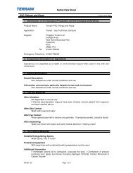
SYSTEM CONTROL INSTALLATION, OPERATION AND SERVICE MANUALFIGURE 8: System Control Troubleshooting ChartIf control is not working properly, disconnect power to control <strong>and</strong> check for signsof physical damage to the front <strong>and</strong> back of the circuit board, water damage (corrosion)or scorching. If damage is found, identify <strong>and</strong> rectify source ofdamage. Replace circuit board (P/N 10090102), if it has permanent damage.Is the line powerindicator on?NoCheck the power supplyto the system controlpanel. Is it on?NoRectify power supplyproblem.YesAdjust thermostat setpoint to call for heat.Does the pumpcome on?NoIs external wiring to thepump OK?NoYesIs the correct contactorselected for thepump?NoYesRefer to burner troubleshootingin either theCORAYVAC ® orBLACKHEAT ® <strong>Installation</strong>,<strong>Operation</strong> <strong>and</strong> <strong>Service</strong><strong>Manual</strong>s.Rectify.Fit the correct contactor.YesDoes the zone lightcome on?NoDoes the pressure switchlight come on?YesIs the thermostat connectedto the correct terminal at thesystem control.NoRectify.NoIs external wiring to thepressure switch OK?NoYesRefer to burner troubleshootingin either theCORAYVAC ® orBLACKHEAT ®<strong>Installation</strong>, <strong>Operation</strong> <strong>and</strong><strong>Service</strong> <strong>Manual</strong>s.YesContactRoberts-Gordon Europe Ltdat www.rg-inc.com.Rectify.YesDo the incorrect zonelights or all zonelights come on?YesAre the zone controlswired correctly?NoTurn off power <strong>and</strong> correctwiring.YesContactRoberts-Gordon Europe Ltdat www.rg-inc.com.NoDo the burners in thezone come on?NoIs external wiring to thezone OK?YesHas the system beencommissioned?NoRefer to the burner start upinstructions in either the CORAYVAC ®or BLACKHEAT ® <strong>Installation</strong>, <strong>Operation</strong><strong>and</strong> <strong>Service</strong> <strong>Manual</strong>s.NoYesYesRectify.Refer to burner troubleshootingin either theCORAYVAC ® orBLACKHEAT ®<strong>Installation</strong>, <strong>Operation</strong> <strong>and</strong><strong>Service</strong> <strong>Manual</strong>s.Do the burners turn offwhen the thermostat issatisfied?NoContactRoberts-Gordon Europe Ltdat www.rg-inc.com.YesDoes the pump turn offfollowing post purge period?NoContactRoberts-Gordon Europe Ltdat www.rg-inc.com.YesTroubleshoot ends.ContactRoberts-Gordon Europe Ltdat www.rg-inc.com.12
SECTION 6: REPLACEMENT PARTSSECTION 6: REPLACEMENT PARTSDANGERWARNINGElectrical Shock HazardExplosion HazardFire HazardCarbon Monoxide HazardUse only genuine ROBERTS GORDON ® replacement parts per this installation, operation <strong>and</strong>service manual.Failure to follow these instructions can result in death, electric shock, injury or property damage.FIGURE 9: System Control Internal Components DiagramItem Description Part Number1 Transformer N/A2 Board Assembly 1009010213
SYSTEM CONTROL INSTALLATION, OPERATION AND SERVICE MANUAL6.1 Replacement Parts InstructionsDANGERElectrical Shock HazardDisconnect electric before service.More than one disconnect switch may berequired to disconnect electric to the unit.Failure to follow these instructions can resultin death or electrical shock.WARNINGExplosion HazardTurn off gas supply to heater before service.Failure to follow these instructions can resultin death, injury or property damage.6.1.1 TransformerThe transformer on the board cannot be replaced.See Page 13, Figure 9, Item 1.6.1.2 Microprocessor ProgramingThe microprocessor may be re-programed by areprograming device.Should the microprocessor program become suspectduring troubleshooting, consult Roberts-GordonEurope Ltd.14