Air release valves
Air release valves
Air release valves
- No tags were found...

Create successful ePaper yourself
Turn your PDF publications into a flip-book with our unique Google optimized e-Paper software.
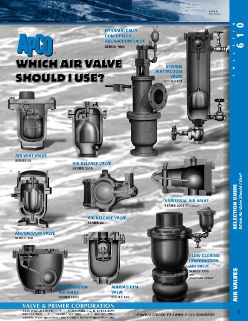
SPECIAL SERVICE AIR VALVESHYDRAULICALLY CONTROLLEDAIR/ VACUUM VALVEUsed for positive pipeline protection against damaging pressure surges. The operating principleof this valve is the same as the CONVENTIONAL <strong>Air</strong>/ Vacuum Valve with one exception …Hydraulically Controlled <strong>Air</strong>/ Vacuum Valves are normally open (because the heavy cast float is notbuoyant) and slowly close after spilling a regulated volume of water to minimize a pressure surge.This valve provides excellent pipeline protection against primary and secondary surge pressureswhich usually occur when filling or draining a pipeline. The closing time of this valve is variable andadjustable by means of a self enclosed hydraulic control system. See Bulletin 70006 1 0B U L L E T I NSeries 7000SYPHON AIR VALVE(MAKE AND BREAK)CUSTOM MADESYPHON AIR VALVES are a unique type of <strong>Air</strong>/Vacuum Valve incorporating apaddle which hangs down into the main pipeline flow stream. The valve willallow a syphon flow to be developed and maintained. Subsequently should thesyphon flow reverse, the paddle swings in reverse causing the float to drop andbreaking the syphon. The APCO Syphon <strong>Air</strong> Valve requires no electrical connectionsor regular maintenance and is ideally suited for remote outdoor environments.In recent years with the emphasis on energy conservation, consultingengineers for water and waste water, often consider pumping by means of asyphon loop. APCO SYPHON AIR VALVES are ideally suited for this application.Solenoid <strong>valves</strong> for small diameter syphons, or pneumatically operated butterfly<strong>valves</strong> for large diameter syphons, may also be adapted for this application, butinstallation and maintenance is complicated and cumbersome. For example,power lines and air lines must be installed to operate these <strong>valves</strong>. An air compressoris also needed. APCO SYPHON AIR VALVES are mechanically operated,requiring no auxiliary power. They merely respond to flow, in either direction, tomake the syphon or break it. Maintenance is virtually non-existent.Series 5200 available in sizes 3”-16” for syphons up to 60” in diameter.SELECTION GUIDEWhich <strong>Air</strong> Valve Should I Use?NOAIROUTFAST AIR INVACUUM RELIEF/AIR INLET VALVESVacuum Relief/<strong>Air</strong> Inlet Valves are large orifice one way<strong>valves</strong>. They permit air to enter the pipeline or system (tobreak the vacuum), but no air escapes when the systempressure returns to positive.Vacuum Relief/<strong>Air</strong> Inlet Valves are normally closed springloaded<strong>valves</strong> that will respond to a vacuum in the pipeline.The Vacuum Relief/<strong>Air</strong> Inlet Valve is designed to open with aminimal 1/4 PSI pressure differential across the orifice.Higher or lower settings are available from the factory.Vacuum Relief/<strong>Air</strong> Inlet Valves are available in combinationwith any of the APCO <strong>Air</strong> Release Valves (Bulletin 600) topermit full flow air into the pipeline and slow air out of thepipeline through the <strong>Air</strong> Release Valve orifice. Series 1500.FAST AIR INSLOW AIR OUTAIR VALVESSee Bulletin 1500129 7
PUMP PROTECTORSPUMP PROTECTORS are an inexpensive way to protecta very expensive Centrifugal Pump from damage due toloss of prime. The Pump Protector is made up of twocomponents; an Automatic <strong>Air</strong> Release Valve and a WaterLevel Control Switch. The Automatic <strong>Air</strong> Release Valveallows air from the suction line and pump volute to bevented. The Water Level Control Switch senses the waterlevel rising…indicating the pump is primed or the level isfalling…to indicate loss of prime and then makes orbreaks the electrical circuit to the pump. Additionally ahorn or a warning light may be provided. Low in cost.Installation and maintenance is simple. Series 2123P.See Bulletin 645.AIR VALVES FOR VERTICALTURBINE PUMPSAIR VALVES FOR VERTICAL TURBINE PUMPS are essential toprevent large volumes of air entering the water system each time the pump isstarted and to break a vacuum when the pump stops. <strong>Air</strong> Valves For VerticalTurbine Pumps are basically <strong>Air</strong>/Vacuum Valves. However, additional featuressuch as an internal Water Diffuser or external air Throttling Device or inlet waterSurge Check are essential to suit these <strong>valves</strong> for use on Vertical Turbine deepwell pumps. Without these features the basic <strong>Air</strong>/Vacuum will most likely spillsubstantial amounts of water before shutting off, or it may not shut off at all.These features will prevent premature closure due to the air in the suction columnbeing saturated with moisture.See Bulletin No. 586 & 601INSTALLATIONInstall the <strong>Air</strong>/Vacuum Valve on the discharge side of thepump as close to the Check Valve as possible. An APCOCheck Valve is recommended.See Bulletin 769, “Which Check Valve Should I Use?”It is recommended an APCO Shut Off Valve be installed belowthe <strong>Air</strong>/Vacuum Valve for inspection and future maintenance.CHECK VALVEAIR/VACUUMVALVEBENEFITS OF THROTTLING DEVICE ON TURBINE SERVICEA throttling device permits the operator to restrict the flow of air escaping from the valve and establisha back-pressure slowing the rising column of water. The surge in the line is thereby reduced. This actionresults in a smoother, trouble-free operation saving maintenance money. A throttlingdevice is available on APCO <strong>Air</strong>/Vacuum Valves from the 1/2” through the 6” size.See Bulletin 586Special Conditions: Or High Service Pumps: (Above 150 PSI)When pump discharge velocities are 10 F.P.S. or more, use a surge check unit with air/vacuum <strong>valves</strong> tominimize water hammer. Pipe the discharge outlet back to the well to muffle noise and contain spillage.See Bulletin 613 “Slow Closing <strong>Air</strong> and Vacuum Valves”When the pump is operating against a positively closed discharge valve, use a Hydraulically Controlled<strong>Air</strong>/ Vacuum Valve to prevent any surge from occurring before the discharge valve opens.See Bulletin 7000DOUBLE Patented ACTINGTHROTTLING Double Acting DEVICEThrottling DevicePATENTED130 8
TYPICAL AIR VALVE APPLICATIONSAIR RELEASE VALVES FOR CENTRIFUGAL PUMPSAn <strong>Air</strong> Release Valve mounted on the volute of a pump as shown in the illustration below, will rid the pump of entrapped air.The <strong>Air</strong> Release Valve will be furnished upon request with a Vacuum Check, which will permit air to pass out, but not in. Thisis especially desirable with volatile fluid. Model 55 is standard with a vacuum check. See Bulletin 600Vacuum Check is optional on all other <strong>Air</strong> Release Valves.Check the tapped hole on the volute of the pump. If 1/2” or larger, select a valve with same inlet size from table, and mountper Figure A. If 3/8” or less, use 1/2” #55 valve mounted on suction side per Figure B. Check the table to see that <strong>valves</strong>elected can handle maximum pressure involved. When ordering specify working pressure.Models 50 & 55 FACTORY MUTUAL (FM) APPROVED AND UNDERWRITERS (UL) LISTED6 1 0B U L L E T I NVALVEMODELNUMBERINLETSIZENPTSTANDARD*MATERIALMAXIMUMPRESSURE50 .5”, .75”, 1” Cast Iron 300PSI55 .5” Cast Iron 150 PSI65 .75” Cast Iron 150 PSI200A 1” Cast Iron 300 PSI200 2” Cast Iron 300 PSI205 2” Cast Iron 800 PSI206 2” Cast Iron 1500 PSI* Other materials, such as Stainless Steel,Steel, Bronze, etc., are available.1”1/4”APCO AIR RELEASE VALVESTORAGETANKFLOWAPCO SILENTCHECK VALVECENTRIFUGAL PUMPFLOWFLOWGATE VALVEHOSEFLOWSELECTION GUIDEWhich <strong>Air</strong> Valve Should I Use?<strong>Air</strong> Release Valves for liquid fuels are installed and operateexactly the way standard water <strong>Air</strong> Release Valves do onwater lines. However, one main difference does exist andthat is in the design of the float. The float of the Fuel <strong>Air</strong>Release Valve is designed to have greater buoyancy thanthe float in a standard Water <strong>Air</strong> Release Valve. Additionalbuoyancy is essential to overcome the lower specific gravityof the various liquid fuels, to insure tight shut off, and toprevent dangerous spilling of fuels from the <strong>Air</strong> ReleaseValve.Caution: Standard Water <strong>Air</strong> Release Valves must not beused on Fuel lines. When ordering or specifying APCO <strong>Air</strong>Release Valves for fuel service, add the suffix “F” to themodel number of the valve, ie; the model 200 <strong>Air</strong> ReleaseValve becomes model 200F; the model 55 <strong>Air</strong> Release Valvebecomes the model 55F, etc. See Bulletin 6510AIR VALVES131 9
AIR ELIMINATORSWELL POINT SYSTEMSIn well point and similar systems which are subject to largeirregular slugs of air, the <strong>Air</strong> Eliminators are excellent becauseof their capacity to trap and hold the slug of air and then dischargeit into the atmosphere. Where there is a negative pressurein the line it is necessary to attach a vacuum line to thevalve orifice. This insures that any air which collects in thevalve will be drawn off when the valve opens.APPLICATION:<strong>Air</strong> Eliminators are especially valuable for use ongasoline and oil metering systems, where it is essentialto eliminate any air or vapor in the fluid, before itreaches the meter, thus preventing a false reading andincreased cost to the buyer.VACUUMLINE #220GROUNDLEVELWATER LEVELWELL POINTSMOBILE PUMPING UNITAvailable in sizes 2” thru12” constructed to A.S.M.E.code standards for maximumprotection.AIR RELEASE VALVE FOR PRESSURE FILTERSPUMPRAW WATERTypicalFilter SystemAPCOTURBINE AIRVALVEAPCO SILENTCHECK VALVEAPCOAIR RELEASEVALVEPRESSUREFILTER TANKSee Bulletin No. 586 & 640STORAGETANKFINISHED WATERPressure Filter Tanks are used by many Municipalities andIndustrial water systems.Every Pressure Filter needs an <strong>Air</strong> Release Valve to <strong>release</strong>air entrapped in normal operation (in some systems air isinjected into the water for the aeration process).Many different APCO <strong>valves</strong> have been used successfullyfor this purpose, but we recommend the APCO 1/2”–No. 55<strong>Air</strong> Release Valve as being most suitable for filter service.The <strong>Air</strong> Valve should be mounted on top of the filter tankand in systems where a battery of filters are used, eachtank should have its own air valve.In filter systems serviced by a deep well turbine pump, anAPCO turbine air valve and an APCO Silent Check Valveinstalled adjacent to the pump will provide a fully protectedsystem.TYPICAL AIR VALVE APPLICATIONSAt all high points in a water line, whether domestic water, hot water, orcold water for cooling - AIR WILL ACCUMULATE AND MUST BERELEASED. This is also true where a large amount of air is encountered -as with <strong>Air</strong> Injection of Chlorine into the water system. AIR WILL ACCU-MULATE AND MUST BE RELEASED.The APCO-50 <strong>Air</strong> Vent Valve installed at these high points will <strong>release</strong> theaccumulated air to insure unrestricted flow of the water and minimize theproblem of annoying and sometimes damaging water hammer.The standard APCO-50 <strong>Air</strong> Vent Valve with 3/32” orifice should providemore than adequate venting for these installations.50 AIR VENT VALVE132 10
200A W/ VACUUM CHECKAIR RELEASE VALVE3/16” ORIFICE (HIGH CAPACITY)INLET1” OR 2”WATERWITHAIRANDGASESFROMBOILER AIROR HEAT SEPARATOREXCHANGERINLET1/2” - 3/4”OR 1PRESSUREREDUCING VALVEWITH CHECKCOLD WATER 1FILLPRESSUREGAUGEDRAIN50 AIR VENTW/ 3/32” ORIFICE50 AIR VENTSUCTIONDIFFUSERWATERPRE-CHARGINGAIR CONNECTIONAIRPRESSURIZED TANK(BLADDER TYPE)TYPICAL AIR BAG TANK INSTALLATION WITH AIR SEPARATORSee Bulletin 50TRIPLE DUTY VALVETO SYSTEMSYSTEMPUMPThe vast majority of buildings (over two stories),utilizing a central hot water and chilled water, Heating/Cooling system, require reliable positive shut-off <strong>Air</strong> Ventsand high venting capacity <strong>Air</strong> Release Valves. This applicationdemands rugged long lasting type APCO <strong>Air</strong> Valves.The Cheap variety - throw away type vents - don’t measureup to the requirements of this application.The <strong>Air</strong> Valves ideally suited to this application are the APCOModel 200A/VC and Model 50. The purpose of the 50 <strong>Air</strong> Ventis to rid the piping system of small pockets of air which accumulateat all high points that would otherwise restrict or stopflow due to an air block.The purpose of the 200A/VC is to <strong>release</strong> air, particularlyduring initial filling of the water system, but also after fillingwhen entrained air from the boiler or heat exchanger, must bevented to atmosphere from the <strong>Air</strong> Separator Tank.The 200A is equipped with a vacuum check to prevent airfrom re-entering the <strong>Air</strong> Separator.6 1 0B U L L E T I NAIR RELEASE VALVES FOR HYDRO-PNEUMATIC WATER TANKSAPCO Model 55 <strong>Air</strong> Release Valves are used on hydro-pneumatic water tanks. To automatically prevent the tank from becomingair-bound or water-logged.APCO Model 54 Pressure Relief Valves protect water-air balance in hydro-pneumatic tanks during periods of excessive demands.NEW — PATENTED! APCO MODEL 2001 UNIVERSAL AIR VALVE• FULLY SELF-COMPENSATING orifice size is not limited by operating pressure• UNIVERSAL APPLICATION for service between 5 and 1500 PSI in one compact valve• ALL STAINLESS STEEL construction with resilient seals• VENTING CAPACITY full 1/2” discharge orifice regardless of pressure• STANDARD OPERATING TEMPERATURE RANGE: -70° to 250°F (-57° to 121°C)APCO MODEL 2001An automatic air <strong>release</strong> valve that willoperate at pressures from 5 to 1500 PSI.The air <strong>release</strong> valve has one orifice forexhausting air and a second orifice,exposed to atmosphere but always sealed.Because of the equalization of pressuresmade possible by the provision of the firstand second orifices, this valve will vent airirrespective of the pressure within the valve.Available in 1” and 2” NPT size.APCO — THE INNOVATORIN AIR RELEASE VALVETECHNOLOGY.U.S. Patent #5,090,439©2000 Valve & Primer Corporation8 3/81/2 ORIFICE1/2 NPT12 7/85 3/41/2 ORIFICE ARV5-1500 PSIG MAX1” or 2” NPT MAXTHESE PRODUCTS ARE NOT MFG., SOLD OR INTENDED FOR PERSONAL, FAMILY OR HOUSEHOLD USE.SELECTION GUIDEWhich <strong>Air</strong> Valve Should I Use?AIR VALVES133 11
SIZING AIR/VACUUM VALVES FOR PIPELINESGeneral explanation of operation: APCO <strong>Air</strong>/Vacuum Valves open whenever the internal pressure of the pipeline approaches anegative value, allowing the water level in the valve to lower and the float to drop from the seat. Their function is to vent large volumesof air from pipelines when they are initially filled and to allow air to re-enter the lines to break a vacuum. On the TypicalEngineers Profile, the gradients are usually indicated. These can then be used for pipeline slopes for calculating the flow down thepipeline. A minimum valve size is established by finding the size for filling, which is usually less than the drainage flow. We use a 2psi pressure differential for the filling flow, 5 psi for the drainage flows. Above 2 psi, the air flow out across the valve orificebecomes so great, it may cause two problems: 1] The valve may close prematurely due to turbulence, trapping an air pocket in thesystem; 2] When the valve closes, the abrupt cessation of flow may create substantial pressure rise and slam, which may damagethe air valve or pipeline. The 5 psi differential for inflowing air represents a safe average for protecting the pipeline and gasketedjoints from damage due to vacuum.1. Calculate necessary <strong>valves</strong> independently for each high point line.2. Consider more severe of the two gradients adjacent to each high point.3. Determine maximum rate of flow in cubic feet per second which canoccur in this gradient for both filling and draining of the line. Always besure to take the highest possible rate of flow under either circumstance(filling or draining).To calculate rate of flow:If the line is being filled by pumpGPM of pumpRate of flow C.F.S. =449If the line is being drained by gravityRate of flow in C.F.S. = 0.08666 (SD 5 )1/2Where S. = Slope (in feet per foot of length)D. = Diameter of pipe (inches)4. Valve to be installed at this high point must <strong>release</strong> or re-enter anamount of air in C.F.S. equal to the maximum possible flow of water inC.F.S. immediately adjacent to this now determined high point.5. To economize in the size of <strong>valves</strong> selected, final step is to determine themaximum pressure differential which can be tolerated across the valveorifice consistent with the required flow of air in C.F.S. already determined.6. To determine this maximum tolerable differential pressure, it is necessaryto calculate if there is a risk of line collapse from vacuum. This condition isusually only present in thin-walled steel lines above 24”. To calculatecollapsing pressure for thin-walled-cylindrical pipe.P = 12500000 3( T DWhere P = Collapsing pressure (PSI)T = Thickness of pipe (inches)D = Diameter of pipe (inchesIncludes Safety Factor of 4(7. For draining and air flow in, use the maximum pressure differential calculated,or 5 psi, whichever is lower. Enter the graph with this differential(never greater than 5 psi) and the flow found during draining to select theappropriate valve to protect your line from collapse and water column separationdue to vacuum.8. For filling and air flow out, next enter the graph with the maximum rateat which the line can be filled, and use a 2 psi differential pressure. Thisvalve size is sufficient to vent all air from the line before valve closure. Thisensures maximum performance from the line.9. Compare the sizes calculated in steps 7 & 8 - use whichever size islarger for the total protection of your system.10. These <strong>valves</strong> should be installed on the high point with a shut-off valvebelow them.11. The same procedure should be followed for each individual high point.12. If the line lacks clearly defined high points, or they are separated bylong stretches of uniform gradient, it is recommended that the proper<strong>valves</strong> be selected as explained above and duplicate installations be madeat regular intervals of 1/4 to 1/2 mile at the engineer’s discretion.To Ensure Maximum Capacity from the Pipe LineWhen a line is in operation, <strong>Air</strong> Pockets collect both at the highpoint and for a distance down stream from the high point. To<strong>release</strong> this <strong>Air</strong>, install the APCO <strong>Air</strong>/Vacuum Valve along with a2”—APCO No. 200A <strong>Air</strong> Release Valve at the high point and asecond <strong>Air</strong> Release Valve a short distance downstream.SIZINGUSE APCO SLIDE RULE AIRVALVE COMPUTERORAPCO APSLIDE SOFTWAREPERFORMANCE GRAPH FOR AIR/VACUUM VALVEAIR INFLOW/OUTFLOW THRU VALVE IN STANDARD CUBIC FEET OF FREE AIR PER SECOND, (SCFS)134 12CURVES SHOWN ARE ACTUAL FLOW CAPACITIES AT 14.7 PSI BAROMETRIC PRESSUREAND AT 70 °F TEMPERATURE BASED ON ACTUAL TEST.THESE FIGURES ARE NOT MERELY FLOW CAPACITIES ACROSS THE ORIFICE,BUT FLOW CAPACITIES ACROSS THE ENTIRE VALVE.IN THE TEST SET-UP, AIR APPROACH VELOCITY IS NEGLIGIBLE, THEREFORE, ACTUALFLOW CAPACITY EXCEEDS THE VALUES SHOWN ON CHART.2000 1000 500 300 200 100 50 40 30 20 10 8 7 6 5 4 3 2 1 0.8 0.6 0.4 0.3 0.224” 20”18”16”14”12” 10” 8” 6” 4” 3” 2” 1”INFLOW1⁄2” VALVE SIZEVALVE & PRIMER CORPORATION1420 WRIGHT BLVD. • SCHAUMBURG, IL 60193-4599847.524.9000 • FAX:847.524.9007 • 800.323.6969website: www.apco<strong>valves</strong>.com • e-mail: factory@apco<strong>valves</strong>.comPRESS. DIFF. ACROSS VALVE IN PSI654321123456VACUUM ACROSS VALVE IN PSIVALVE SIZEOUTFLOW1⁄2” 1” 2” 3” 4” 6” 8” 10” 12”14”16”18”20”24”0.2 0.3 0.4 0.60.8 1 2 3 4 5 6 7 810 20 30 40 50 100 200 300 500 1000 2000TESTS CONDUCTED BY:PHILLIP PETROLEUM COMPANYENGINEERING DEPARTMENT — TEST DIVISIONEDMOND PLANT PLANT FEB. 2, 1961SOUTHERN RESEARCH RESEARCH INSTITUTEBIRMINGHAM, ALABAMA MAY 8, 1959VALVE & PRIMER CORPORATION HEREBY RESERVES THE RIGHT TO CHANGE ANYCOMPONENT PARTS WHICH, IN THE OPINION OF ITS ENGINEERING DEPARTMENT,WILL IMPROVE THE PRODUCT OR INCREASE ITS SERVICEABILITY.DIMENSIONS ARE FOR ILLUSTRATIVE PURPOSES ONLY. PLEASE CONFIRM ALL DIMENSIONALINFORMATION WITH VALVE & PRIMER CORPORATION ENGINEERING DEPARTMENT.