Robinair 92500 Transmission Fluid Exchanger - NY Tech Supply
Robinair 92500 Transmission Fluid Exchanger - NY Tech Supply
Robinair 92500 Transmission Fluid Exchanger - NY Tech Supply
- No tags were found...

You also want an ePaper? Increase the reach of your titles
YUMPU automatically turns print PDFs into web optimized ePapers that Google loves.
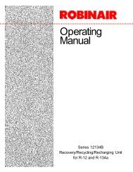
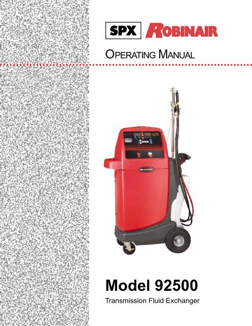
OPERATING MANUAL○ ○ ○ ○ ○ ○ ○ ○ ○ ○ ○ ○ ○ ○ ○ ○ ○ ○ ○ ○ ○ ○ ○ ○ ○ ○ ○ ○ ○ ○ ○ ○ ○ ○ ○ ○ ○ ○ ○ ○ ○ ○ ○ ○ ○ ○ ○ ○ ○ ○ ○ ○ ○ ○ ○ ○ ○ ○ ○ ○ ○ ○ ○ ○ ○ ○ ○ ○ ○ ○ ○ ○ ○ ○ ○ ○ ○Model <strong>92500</strong><strong>Transmission</strong> <strong>Fluid</strong> <strong>Exchanger</strong>
<strong>Transmission</strong> <strong>Fluid</strong> <strong>Exchanger</strong> UnitModel: <strong>92500</strong>SAFETY DEFINITIONS: Follow all WARNING, CAUTION, IMPORTANT, and NOTE messages in this manual.These messages are defined as follows: WARNING means you may risk serious personal injury or death;CAUTION means you may risk personal injury and property damage or serious unit damage; IMPORTANT meansyou may risk unit damage; and NOTEs provide clarity and helpful tips. These safety messages cover situationsROBINAIR is aware of. ROBINAIR cannot know, evaluate, and advise you as to all possible hazards. You mustmake sure all conditions and procedures do not jeopardize your personal safety.COPYRIGHT: No part of this manual may be reproduced, stored in a retrieval system, or transmitted in any formor by any means (electronic, mechanical, photocopy, recorded, or otherwise) without the prior written permission ofROBINAIR.DISCLAIMER: All information, illustrations, and specifications contained in this manual are based on the latestinformation available at the time of publication. The right is reserved to make changes at any time withoutobligation to notify any person or organization of such revisions or changes. Further, ROBINAIR shall not be liablefor errors contained herein or for incidental or consequential damages (including lost profits) in connection with thefurnishing, performance, or use of this material. If necessary, obtain additional health and safety information fromthe appropriate government agencies and the vehicle and oil manufacturers.WARNINGSTo prevent personal injury and/or property damage,Allow only qualified personnel to operate the unit.Study, understand and follow all instructions and warnings before operating thisdevice. The operating instructions and safety precautions must be read anddiscussed in the operator’s native language, if the operator cannot read theseinstructions.- Si el operador no puede leer o comprender estas instrucciones de funcionamientoy las precauciones de seguridad, éstas deberán leerse y comentarse en el idiomanativo del operador.- Si l’utilisateur ne peut pas lire les directives relatives au fonctionnement et auxmesures de sécurité, celles-ci doivent pouvoir être transmises à l’utilisateur dans salangue maternelle.Wear protective equipment, including safety goggles. Disconnect hoses withextreme caution.Keep tools, electrical cords, and hoses away from moving engine parts.Vent exhaust to the outside while running the vehicle. Never run a vehicle withoutadequate ventilation in the work area.Before starting the vehicle’s engine, verify the vehicle is in PARK or NEUTRAL, withthe emergency brake ON.IMPORTANT!Review current local, state, and federal statutes, cases, laws, and regulations to determine the currentstatus and appropriate disposal method for transmission oil. It is the responsibility of the user todetermine if a material is a hazardous waste at the time of disposal. Ensure that you are in compliancewith all applicable laws and regulations.
Table of ContentsSafety Warnings ........................................................... inside front coverIntroduction ......................................................................................... 2General Description .........................................................................................2Glossary of Terms ............................................................................................2Component Identification and Location ............................................................3Unit Front View .........................................................................................3Control Panel ............................................................................................4Initial Setup .....................................................................................................5Accessory Kit ............................................................................................5Registering the Unit ..................................................................................5Application Notes ......................................................................................5Helpful Tips ...............................................................................................5Operating Procedures ...................................................................................6Dipstick Only Mode ...................................................................................6Dipstick/Cooler Mode ................................................................................8Cooler Only Mode ...................................................................................10Manual/Top-Off Mode .............................................................................11Drain Waste Tank ...................................................................................12Total Count .............................................................................................13Changing <strong>Transmission</strong> <strong>Fluid</strong> Types.......................................................13Error Messages ..............................................................................................14Maintenance...................................................................................................14Replacement Adapters...................................................................................15Replacement Parts.........................................................................................18Warranty Statement ............................................................... inside back cover<strong>Transmission</strong> <strong>Fluid</strong> <strong>Exchanger</strong>1
IntroductionGeneral DescriptionThe <strong>92500</strong> provides an easy, efficient way of replacing automatic transmissionfluid in a vehicle. The <strong>Exchanger</strong> removes the used transmission fluid andreplaces it with new fluid, which reduces the harmful contaminants andrestores the fluid properties, extending the life of the vehicle’s transmission.Glossary of TermsATF — Automatic transmission fluid (oil).Unit — The transmission fluid exchanger.Dipstick Only Mode —Transfers used ATF and new ATF through thetransmission’s dipstick tube by running a hose directly into the transmissionfluid pan. This mode eliminates the need to remove the cooler lines.Dipstick/Cooler Mode — Initially transfers used ATF and new ATF throughthe transmission’s dipstick tube. Then with the engine running, new ATF ispumped into the transmission through the dipstick tube, while the used ATF isevacuated through the cooler lines. This mode provides the quickest transfer ofused and new ATF.Cooler Only Mode — Transfers used ATF and new ATF through the oil coolerlines. Use this mode if the transmission does not have a dipstick.Manual/Top-Off Mode — Manually adds or removes fluid to or from thetransmission pan. Use this mode if it is necessary to remove the transmissionpan, or to add fluid when using another mode.Drain Waste Tank — Transfers used ATF from the internal waste tankthrough the nylon transfer hose to an external waste ATF holding tank.Total Count — Displays the number of ATF exchanges performed.Pause/Abort — Pauses or aborts a transfer. Press button once to pause.Press and hold button to abort. Note: When abort is selected, the unit resetsitself. All measurements will be cancelled.IMPORTANT!Review current local, state, and federal statutes, cases, laws, and regulationsto determine the current status and appropriate disposal method for theautomatic transmission fluid. It is the responsibility of the user to determineif a material is a hazardous waste at the time of disposal. Ensure that you arein compliance with all applicable laws and regulations.2© 2004 SPX Corporation
IntroductionComponent Identification and LocationUnit Front ViewHose HangerDipstick Wand AssemblySelector ValveAssemblyHose HangerIndicator LightNylon HoseControl PanelShelf for tools andaccessoriesBuilt-in HandleTank for new oilPolypropyleneCabinet fordurability and lightweightLarge Wheels forease of mobilityLocking Casters<strong>Transmission</strong> <strong>Fluid</strong> <strong>Exchanger</strong>3
IntroductionComponent Identification and Location continuedControl PanelON/OFF Indicator LightMode LED Indicators:Dipstick OnlyDipstick/CoolerCooler OnlyManual/Top-OffDrain Waste TankTotal CountPause/AbortButtonArrow Buttons:DownUpNew <strong>Fluid</strong><strong>Transmission</strong> <strong>Fluid</strong> <strong>Exchanger</strong>in...DIPSTICK ONLYDIPSTICK/COOLERCOOLER ONLYMANUAL/TOP-OFFDRAIN WASTE TANKTOTAL COUNTSTARTREVERSEDPOLARITYSERVICE END CHECKSTART SERVICE LEVELENGINETransfer LEDs:To Trans From TransSUPPLYLINEFINISHRETURNLINESELECT...ReplacedENTER<strong>Fluid</strong> outLight Indicators:Reversed Polarity<strong>Supply</strong> LineReturn LineSelect ButtonEnter ButtonStart Service LEDStart Engine LEDIOFinish LEDCheck Trans Level LEDEnd Service LEDON/OFFSwitchTransfer Indicators: ATF InATF OutNew <strong>Fluid</strong> In — Displays amount of fluid added.Replaced <strong>Fluid</strong> Out — Displays amount of fluid extracted.UP/DOWN Arrows — Adjusts amount of fluid in or out.Pause/Abort — Pauses or aborts a transfer.Error Message Indicators — Displays error message.Mode Indicators — Identifies procedures available.Select Button — Selects the desired mode or procedure.Enter Button — Accepts mode selected and starts the ATF exchange.Display Screens — Displays operational or error information.Transfer Indicators and LEDs — Indicates the transfer that is presentlytaking place.ON/OFF Power Switch — Turns the unit on.4© 2004 SPX Corporation
Initial SetupAccessory KitUnpack Accessory Kit located inside the rear doorof unit. Accessory Kit includes: Adapter set,warranty card, and hose hanger bracket.Attach Hose Hanger Bracket1. Drop tube all the way down over existing tubeon unit.2. Rotate to align holes.3. Insert screw into the middle hole.Hose Hanger BracketApplication NotesFord Taurus with a 3.0 liter V6 requires theremoval of the vent cap located behind theshifter linkage on top of transmission beforeservice. This will minimize “overfilling” due tolack of headroom in the transmission housing.Low pressure transmissions require thetransmission be left in neutral with the parkingbrake secured during the “dynamic” (enginerunning) phase of the ATF service.Import vehicles, with small dipstick tubeopenings, require the 529740 flexible nylonhose, which has a smaller blue section at theend, in place of the 529734 hose.Align holesRegistering the UnitNylon HoseStorageTo validate the warranty provided by SPXROBINAIR, complete the warranty card includedin the accessory kit, and mail it within ten daysfrom the date of purchase.Helpful TipsTo avoid oil spillage, turn unit on before removingthe flexible nylon hose from its storage area.Press the Pause/Abort once to pause an operation;press ENTER to continue the operation.Press and hold the Pause/Abort button todiscontinue an operation and to reset the unit.For the quickest and most accurate exchange,ensure transmission is warmed to normaloperating temperatures.IMPORTANT: To prevent damage to thevehicle, ensure all hoses are correctlyconnected before transferring fluid.<strong>Transmission</strong> <strong>Fluid</strong> <strong>Exchanger</strong>WARNINGThis manual contains important procedures concerning the setup, operation, andmaintenance of the unit. Study and follow all warnings at the beginning of this manual. Donot operate the unit until you have read and understand the contents of this manual. If youdo not understand any of the contents of this manual, notify your supervisor. If the operatorcannot read English, all instructions and safety precautions must be read and discussed in theoperator’s native language.5
Operating ProceduresDipstick Only ModeThe Dipstick Only mode transfers used ATF andnew ATF through the transmission’s dipsticktube by running a hose into the transmissionfluid pan, emptying it of its contents, and thenwith engine running, adding ATF. ATF is thensubtracted until a user specified amount of newATF has been added.Note: Confirm vehicle and transmission are atoperating temperature before initiating service.Power Up1. Connect the power cord to a 12V DCbattery: red to the positive post and black tothe negative post.2. Turn the unit on. The Reversed Polarity LEDlights if the power is connected incorrectly.The unit self-tests: The buzzer sounds, allLEDS and displays light, the flexible nylonhose evacuates ATF, and the softwareversion displays.3. Remove dipstick from the transmission tube.4. Insert the unit’s flexible nylon hose into thetransmission dipstick tube as far as possibleto reach the bottom of the oil pan. TheDipstick Only, Dipstick/Cooler, Cooler Only,Manual/Top-Off, Drain Waste Tank, andTotal Count indicators, and the SELECTbutton LEDs are still lit and flashing.5. Press the SELECT button until the DipstickOnly LED is lit.6. Pause until the ENTER LED lights andflashes (about one second).7. Press ENTER to confirm the selection. Theleft display (New <strong>Fluid</strong> In) reads 12 (thedefault quantity in quarts of new ATF to berun into the system).8. Use the arrow keys to select the amount ofquarts to be transferred. (12 quarts is thedefault; minimum is 6 quarts, maximum is 32quarts.)69. Press ENTER to confirm the quantitydisplayed. The alarm sounds, and the StartService and ENTER LEDs flash.Start Service1. With the vehicle engine off, press ENTER tostart the ATF exchange. The following takesplace:a. The unit purges its internal fluid lines.b. Used ATF is then extracted from thetransmission pan until empty.c. The cumulative volume extracted appearson the Replace <strong>Fluid</strong> Out display.d. Through the nylon transfer hose, the unitpumps back into the transmission fluid panthe same volume of new ATF that appearson the Replace <strong>Fluid</strong> Out display.e. The volume of new fluid yet to be pumpedinto the transmission pan is shown on New<strong>Fluid</strong> In display. (The amount designated in“Power Up” step 8 minus the amounttransferred in “Start Service” step 1d.)f. The Start Engine and ENTER LEDs flash.2. Start the vehicle’s engine to circulate the newATF through the transmission system (torqueconverter and cooler lines).3. Press ENTER to confirm the engine isrunning.The exchanger extracts one quart of diluted ATFand returns one quart of new ATF through thehose and back into the transmission fluid pan.The Replace <strong>Fluid</strong> Out and New <strong>Fluid</strong> In displaysrespectively the amount of fluid extracted andthe amount of new fluid to be added. Thisrecycling continues until the selection made instep 8 under “Power Up” is met (i.e., using the12 quart default, Replace <strong>Fluid</strong> Out will be 12and New <strong>Fluid</strong> In will be 0).© 2004 SPX Corporation
Operating ProceduresDipstick Only Mode continuedWhen the selection in step 8 is met, the buzzersounds and the End Service and ENTER LEDslight.4. Press ENTER to confirm that the correctamount of ATF has been replaced. CheckTrans Level LED lights.Check the ATF Level in the Pan1. Remove the flexible nylon hose.2. Insert the dipstick.3. Remove dipstick to check level of fluid.If the fluid level needs to be adjusted, continueon to “Adjust the ATF Level.” If the level issatisfactory, go to step 4 under “Adjust the ATFLevel.”Adjust the ATF Level1. Place the flexible nylon hose in the dipsticktube.2. Press ENTER. The To Trans, From Transand Finish LEDs light.a. If the level is too low, select To TransLED. Press ENTER. Press the up arrow keyto select how much fluid to add (each pressindicates one-tenth of a quart).b. If the level is too high, select From TransLED. Press ENTER. Press the up arrow keyto select how much fluid to take out (eachpress indicates one-tenth of a quart).3. When transfer is complete, go to “Check theATF Level in the Pan.”4. If the level is satisfactory, press SELECTuntil Finish LED lights.a. Wait for one second.b. Press ENTER to confirm the function.c. Press ENTER again.The display reads SR FIN, indicating the serviceis finished.<strong>Transmission</strong> <strong>Fluid</strong> <strong>Exchanger</strong>7
Operating ProceduresDipstick/Cooler ModeInitially transfers used ATF and new ATFthrough the transmission’s dipstick tube. Thenwith the engine running, new ATF is pumpedinto the transmission through the dipstick tube,while the old ATF is evacuated through thecooler lines. This mode provides the quickesttransfer of used and new ATF.Note: Confirm vehicle and transmission are atoperating temperature before initiating service.Identify Cooler Lines1. Disconnect cooler lines, and attach adaptersto the input and output connectors. Theseadapters may be open hoses and/or snap orthreaded fittings.Note: To minimize the total time of the ATFservice, this step may be performed duringthe “static” (engine not running) phase, whenthe used ATF in the transmission pan isbeing exchanged with the new ATF.Power Up1. Connect the power cord to a 12V DCbattery: red to the positive post and black tothe negative post.2. Turn the unit on. The Reversed Polarity LEDlights if the power is connected incorrectly.The unit self-tests: The buzzer sounds, allLEDS and displays light and flash, theflexible nylon hose evacuates ATF, and thesoftware version displays.3. Attach the adapters to the unit’s cooler lineselector valve assembly. Note: The adapterscan be connected to either coupler.4. Confirm connections are secure.5. Remove the dipstick from the transmissiontube.6. Insert the unit’s flexible nylon hose into thetransmission dipstick tube as far as possibleto reach the bottom of the transmission fluidpan. The Dipstick Only, Dipstick/Cooler,Cooler Only, Manual/Top-Off, Drain WasteTank, Total Count indicators, and theSELECT button LEDs are still lit andflashing.7. Press the SELECT button until only theDipstick/Cooler LED is lit.8. Pause until the ENTER LED lights andflashes (about one second).9. Press ENTER to confirm the selection. Theleft display (New <strong>Fluid</strong> In) reads 12 (thedefault quantity in quarts of new ATF to berun into the system).10. Use the arrow keys to select the amount ofquarts to be transferred. (12 quarts is thedefault; minimum is 6 quarts, maximum is 32quarts.)11. Press ENTER to confirm the quantitydisplayed. The alarm sounds and the StartService and ENTER LEDs flash.Start Service1. Press ENTER to start the ATF exchange.The following takes place:a. The unit purges its internal fluid lines.b. Used ATF is then extracted from thetransmission fluid pan until empty.c. The cumulative volume extracted appearson the Replace <strong>Fluid</strong> Out display.d. Through the flexible nylon hose, the unitpumps back into the transmission fluid panthe same volume of new ATF that appearson the Replace <strong>Fluid</strong> Out display.8© 2004 SPX Corporation
Operating ProceduresDipstick/Cooler Mode continuede. The volume of new fluid yet to be pumpedinto the transmission pan is shown on New<strong>Fluid</strong> In display (the amount designated in“Power Up” step 10 minus the amounttransferred in “Start Service” step 1d).f. The Start Engine and ENTER LEDs flash.2. Start the vehicle’s engine to circulate theATF through the transmission system (torqueconverter and cooler lines).3. Press ENTER to confirm the engine isrunning.The unit extracts used ATF from the cooler linesand returns new ATF through the nylon transferhose and back into the transmission fluid pan.The Replace <strong>Fluid</strong> Out and New <strong>Fluid</strong> Indisplays respectively the amount of ATFextracted and the amount of new ATF added.This recycling continues until the selection madein step 10 under “Power Up” is met.When the preset amount is met, the buzzersounds and the End Service and ENTER LEDslight.4. Press ENTER to confirm that the correctamount of ATF has been replaced. CheckTrans Level LED lights.Check the ATF Level in the Pan1. Remove the flexible nylon transfer hose.2. Insert the dipstick.3. Remove the dipstick to check fluid level.If the fluid level needs to be adjusted, continueon to “Adjust the ATF Level.” If the level issatisfactory, go to step 4 under “Adjust the ATFLevel.”Adjust the ATF Level1. Place the flexible nylon hose in the dipsticktube.Note: An alternative method is to disconnectthe red hose from the dipstick wandassembly, and connect it to the selectorvalve assembly.Selector Valve Assembly2. Press ENTER. The To Trans, From Transand Finish LEDs light.a. If the level is too low, select To TransLED. Press ENTER. Press the up arrow keyto select how much fluid to add (each pressindicates one-tenth of a quart).b. If the level is too high, select From TransLED. Press ENTER. Press the up arrow keyto select how much fluid to take out (eachpress indicates one-tenth of a quart).3. When transfer is complete, go to “Check theATF Level in the Pan.”4. If the level is satisfactory, press SELECTuntil Finish LED lights.a. Wait for one second.b. Press ENTER to confirm the function.c. Press ENTER again.Red HoseAdaptersThe display reads SR FIN, indicating the serviceis finished.<strong>Transmission</strong> <strong>Fluid</strong> <strong>Exchanger</strong>9
Operating ProceduresCooler Only ModeTransfers used ATF and new ATF through thecooler lines.Note: Confirm vehicle and transmission are atoperating temperature before initiating service.Identify Cooler Lines1. Disconnect cooler lines, and attach adaptersto the input and output connectors.Power Up1. Connect the power cord to a 12V DCbattery: red to the positive post and black tothe negative post.2. Turn the unit on. The Reversed Polarity LEDlights if the power is connected incorrectly.The unit self-tests: The buzzer sounds, allLEDS and displays light and flash, thedipstick tube holder evacuates ATF, and thesoftware version displays.3. Attach the adapters to the unit’s cooler lineselector valve assembly. Note: The adapterscan be connected to either coupler.4. Disconnect the red hose from the dipstickwand assembly, and connect it to theselector valve assembly.Selector Valve AssemblyRed HoseAdapters8. Press ENTER to confirm the selection. Theleft (New <strong>Fluid</strong> In) display reads 12 (thedefault quantity in quarts of new ATF to berun into the system).9. Use the arrow keys to select the amount ofquarts to be transferred. (12 quarts is thedefault; minimum is 6 quarts, maximum is 32quarts.)10. Press ENTER to confirm the quantitydisplayed. The alarm sounds and the StartEngine and ENTER LEDs flash.11. Start the vehicle’s engine.Start Service1. Press ENTER to start the ATF exchange.The following takes place:a. The unit extracts used ATF from one ofthe cooler lines.b. The amount of ATF extracted appears onthe Replaced <strong>Fluid</strong> Out display (i.e., if 12 wasselected in “Power Up” step 9, and 3 quartswere extracted in step 1a above, Replaced<strong>Fluid</strong> Out will display 9).c. The unit replaces the ATF taken out withnew ATF through the other cooler line.This recycling continues until the selection instep 9 under “Power Up” is met. When theselection is met, the buzzer sounds and the EndService and ENTER LEDs light.2. Press ENTER to confirm that the correctamount of oil has been replaced. CheckTrans Level LED lights.5. Confirm connections are secure.6. Press the SELECT button until only theCooler Only LED is lit and flashing.7. Pause until the ENTER LED lights andflashes (about one second).10© 2004 SPX Corporation
Operating ProceduresCooler Only Mode continuedCheck the ATF Level in the Pan1. Remove the dipstick to check level of fluid intransmission fluid pan. If the vehicle does nothave a dipstick, refer to the vehicle’s servicemanual for the method required to check thefluid level.If the fluid level needs to be adjusted, continueon to “Adjust the ATF Level.” If the level issatisfactory, go to step 4 under “Adjust the ATFLevel.”Adjust the ATF Level1. Press ENTER. The To Trans, From Transand Finish LEDs light.a. If the level is too low, select To TransLED. Press ENTER. Press the up arrow keyto select how much fluid to add (each pressindicates one-tenth of a quart).b. If the level is too high, select From TransLED. Press ENTER. Press the up arrow keyto select how much fluid to take out (eachpress indicates one-tenth of a quart).2. When transfer is complete, go to “Check theATF Level in the Pan.”3. If the level is satisfactory, press SELECTuntil Finish LED lights.a. Wait for one second.b. Press ENTER to confirm the function.c. Press ENTER again.The display reads SR FIN, indicating the serviceis finished.Manual/Top-Off ModeTransfers used ATF and new ATF through thetransmission’s dipstick tube. This mode iscommonly used when the transmission fluid panneeds to be removed (to change gaskets orreplace a filter). When using another mode, thismode is required to top off the ATF fluid level.Note: Confirm vehicle and transmission are atoperating temperature before initiating service.Power Up1. Connect the power cord to a 12V DCbattery: red to the positive post and black tothe negative post.2. Remove the dipstick from the transmissionnoting ATF level, which will determinewhether additional ATF needs to be addedor withdrawn.3. Turn the unit on. The Reversed Polarity LEDlights if the power is connected incorrectly.The unit self-tests: The buzzer sounds, allLEDS and displays light and flash, theflexible nylon hose evacuates ATF, and thesoftware version displays.4. Insert the unit’s flexible nylon transfer hoseinto the transmission dipstick tube as far aspossible to reach the bottom of the oil pan.5. Press the SELECT button until only theManual/Top-Off LED is lit and flashing.6. Pause until the ENTER LED lights andflashes (about one second).7. Press ENTER to confirm the selection. TheCheck Trans Level, To Trans, and FromTrans LEDs light. Drn Pan appears on thedisplay.<strong>Transmission</strong> <strong>Fluid</strong> <strong>Exchanger</strong>11
Operating ProceduresManual/Top-Off Mode continuedAdjust the ATF Level1. In step 2 under “Power Up,” the ATF levelwas determined noting whether ATF neededto be added, subtracted, or it was satisfactory.a. If the level is too low, select To Trans LED.(1) Press Enter.(2) Press the arrow key to select howmuch fluid to add (each press indicates onetenthof a quart).(3) Pause after the correct volume isselected. The ENTER key lights and flashes.(4) Press ENTER to start the service.b. If the level is too high, select FromTrans LED.(1) Press Enter.(2) Press the arrow key to select howmuch fluid to take out (each press indicatesone-tenth of a quart).(3) Pause after the correct volume isselected. The ENTER key lights and flashes.(4) Press ENTER again to start theservice.c. If the transmission fluid pan needs tobe removed, press SELECT until Drn Panappears on the display.(1) Pause until ENTER LED lights (aboutone second).(2) Press ENTER to confirm the function.(3) Press ENTER again to start drainingthe pan. The unit will stop when pan is empty.Refill <strong>Transmission</strong> <strong>Fluid</strong> PanTo refill the transmission fluid pan,1. Press SELECT until the To Trans LED is lit.2. Press ENTER. The amount removed willdisplay on the Replaced <strong>Fluid</strong> Out display.3. Adjust the New <strong>Fluid</strong> In display to match theReplaced <strong>Fluid</strong> Out display.4. Press ENTER.Drain Waste TankTransfer used ATF from the internal waste tankto an external waste ATF reservoir.Power Up1. Connect the power cord to a 12V DCbattery: red to the positive post and black tothe negative post.2. Ensure the unit’s hoses are disconnectedfrom the vehicle.3. Turn the unit on. The Reversed Polarity LEDlights if the power is connected incorrectly.The unit self-tests: The buzzer sounds, allLEDS and displays light and flash, theflexible nylon hose evacuates ATF, and thesoftware version displays.4. Place the flexible nylon hose into an externalwaste ATF reservoir.Start Service1. Press the SELECT button until only theDrain Waste Tank LED is lit and flashing.2. Pause until the ENTER LED lights andflashes (about one second).3. Press ENTER to confirm the selection. Thedisplay reads DRN (XXX), which is theamount left to be drained.When the waste tank is drained, the displayreads SR FIN, indicating service is finished.12© 2004 SPX Corporation
Operating ProceduresTotal CountDisplays the number of ATF exchangesperformed.Power Up1. Connect the power cord to a 12V DCbattery: red to the positive post and black tothe negative post.2. Turn the unit on. The Reversed Polarity LEDlights if the power is connected incorrectly.The unit self-tests: The buzzer sounds, allLEDS and displays light and flash, theflexible nylon hose evacuates ATF, and thesoftware version displays.Start Service1. Press the SELECT button until only the TotalCount LED is lit and flashing.2. Pause until the ENTER LED lights andflashes (about one second).3. Press ENTER to confirm the selection.The total number of services performed isdisplayed; the Finish LED flashes.4. Press ENTER to return to mode selectionafter noting the total number of services.Changing <strong>Transmission</strong><strong>Fluid</strong> TypesTo change transmission fluid type in a new tank:1. Connect the power cord to a 12V DCbattery: red to the positive post and black tothe negative post.2. Insert the flexible nylon hose into a cleanATF container.3. Press the SELECT button until Manual/Top-Off LED lights.4. Press ENTER.5. Press the SELECT button until To TransLED lights.6. Press ENTER.7. Press the UP arrow key until display readsan amount more than what is in the newtank.8. Press ENTER. The unit will pump ATF fromthe new tank into the clean ATF container.9. Turn the unit off when completed. The unitwill clear the lines when it is restarted.<strong>Transmission</strong> <strong>Fluid</strong> <strong>Exchanger</strong>13
Error MessagesER FLO — Return Line is lit. No oil is returning.ER FLO — <strong>Supply</strong> Line is lit. Check new oil reservoir.Reversed Polarity is lit. Check battery connections.Maintenance• Check the flexible nylon hose for cuts and/or kinks.• Filter screens may need to be cleaned. Locate the filter screens inside theunit; clean if necessary.• Cabinet can be kept clean by wiping it down with a clean cloth.• Check wires for cuts and/or damage.14© 2004 SPX Corporation
Replacement Adapters529567 - Complete adapters kit. All replacement adapters describedbelow are included in the kit.Part Order No. Description ApplicationOriginal No.529568 1/4" (M6) Barb Assembly General6304-06529569 5/16" (M8) Barb Assembly General6304-08529570 3/8" (M10) Barb Assembly General6304-10529571 1/4" (M6) Open End Hose General6303-06529572 5/16" (M8) Open End Hose General6303-08529573 3/8" (M10) Open End Hose General6303-10529574 1/2" (M13) Open End Hose General6303-12529575 5/16" x 90 Female Domestic6306-035295766310-103/8" Male x 5/16" Male Domesticand Import529577 3/8" Female Snap Lock Domestic6306-05529578 1/2" Male Snap Lock Chrysler6310-12529579 1/2" Male Angle Step GM6312-01<strong>Transmission</strong> <strong>Fluid</strong> <strong>Exchanger</strong>529580 3/8" Male Angle Step GM6311-0115
Replacement Adapters contd.Part Order No. Description ApplicationOriginal No.529581 5/16" Flare, 7/16" - 24 Assembly Domestic6318-05and Import529582 1/2" - 20 Male (Long End SAE) Ford6308-04529583 1/2" - 20 Female x SAE 45 Degrees Domestic6313-01and Import529584 5/8" - 18 Female x SAE IN Ford6307-045295856318-063/8" Flare, 5/8" - 20 Assembly Domesticand Import529586 5/8" - 18 Female x SAE 45 Degrees Domestic6301-01and Import529587 M14 Banjo Fitting Import6308-14 (2 fittings included in 529567 Kit)529588 M16 Female Swivel Import6310-16529589 5/8" - 18 Female x 45 Degrees Domestic6302-02and Import529590 S/25 x 1/4" NPTM Plug Domestic2025-13 (2 plugs included in 529567 Kit)529591 S/25 x 3/8" NPTM Plug Domestic2025-3316© 2004 SPX Corporation
Replacement Adapters contd.Part Order No. Description ApplicationOriginal No.529592 1/2" to 29/32" x 5/16" Band Clamp General2102-07 (3 clamps included in 529567 Kit)529593 M14 Banjo Bolt Long Import6007-14529594 M14 Cap Nut Import1419-98529595 M14 Copper Washer Import1602-14 (3 washers included in 529567 Kit)529596 S/25 x 3/8" NPTF Plug Domestic2025-325295976308-021/2" x 20 Female Inverted Domesticand Import529598 1/2" x 20 Female SAE Inverted Ford6308-03529599 5/8" x 18 Ford6307-035296006313-021/2" x 20 Male x 45 Degrees Domesticand Import529601 S/25 x 1/4" NPTF Plug Domestic2025-12529734 75" x 5/16" OD Dipstick Tube Adapter Assy.6300-00-65529740 42" x 1/4" OD Dipstick Tube Adapter6300-00-42<strong>Transmission</strong> <strong>Fluid</strong> <strong>Exchanger</strong>17
Replacement PartsIllustration Part Number Description92501 Pump Assembly Replacement92501RBKPump Rebuild Kit90516 New Oil Reservoir Cap92509 Quick Disconnect Coupler, S/25 x 1/4" Female NPT(A in illustration)92510 Directional Valve Rebuilt Kit(B in illustration)92511 Quick Disconnect Plug, S/48 x 1/4" Male NPT(C in illustration)92512 Quick Disconnect Coupler, S/25 x 1/4" Male NPT(D in illustration)92513 Pressure Hose (Red; 92" x 3/8" Barb Assembly)92514 Recovery Hose (Black; 92" x 3/8" Barb Assembly)92515 Cooler Hose (Black; 92" x 3/8" Barb Assembly)92516 Power Cord Assembly92517 Quick Disconnect Coupler, S/48 x 3/8" Male NPT(A in illustration)92518 Quick Disconnect Plug, S/48 x 3/8" Male NPT(D in illustration)18© 2004 SPX Corporation
Limited Warranty<strong>Robinair</strong> Limited Warranty StatementThis product is warranted to be free from defects in workmanship, materials, and components for aperiod of one year from date of purchase. All parts and labor required to repair defective productscovered under the warranty will be at no charge. The following restrictions apply:1. The limited warranty applies to the original purchaser only.2. The warranty applies to the product in normal usage situations only, as described in the OperatingManual. The product must also be serviced and maintained as specified.3. If the product fails, it will be repaired or replaced at the option of the manufacturer.4. Transportation charges for warranty service will be reimbursed by the factory upon verification ofthe warranty claim and submission of a freight bill for normal ground service. Approval from themanufacturer must be obtained prior to shipping to an authorized service center.5. Warranty service claims are subject to authorized inspection for product defect(s).6. The manufacturer shall not be responsible for any additional costs associated with a productfailure including, but not limited to, loss of work time and unauthorized shipping and/or laborcharges.7. All warranty service claims must be made within the specified warranty period. Proof-of-purchasedate must be supplied to the manufacturer.This Limited Warranty does NOT apply if:• The product, or product part, is broken by accident.• The product is misused, tampered with, or modified.© 2004 SPX Corporation <strong>Transmission</strong> <strong>Fluid</strong> <strong>Exchanger</strong>
Visit our web site at%www.robinair.comorCall our Toll-Free<strong>Tech</strong>nical Support Line at800-822-5561in the continental U.S. or Canada.In all other locations, contact your local distributor. To help us serveyou better, be prepared to provide the model number, serial number,and date of purchase of your unit.To validate your warranty, complete the warranty card attached to yourunit, and return it within ten days from date of purchase.NATIONWIDE NETWORK OF AUTHORIZED SERVICE CENTERSIf your unit needs repair or replacement parts, contact the servicecenter in your area. For help in locating a service center, call thetoll-free technical support line.Due to ongoing product improvements,we reserve the right to change design,specifications, and materials without notice.SPX Corporation655 Eisenhower DriveOwatonna, MN 55060-0995 USA<strong>Tech</strong>nical Services: 1-800-822-5561Fax: 1-412-690-2001Customer Service: 1-800-533-6127Fax: 1-800-322-2890Web Site: www.robinair.com526233 Rev. A (12/07/04) <strong>92500</strong> <strong>Transmission</strong> <strong>Fluid</strong> <strong>Exchanger</strong> © 2004 SPX Corporation