CV Circular electric duct heaters - Tecna
CV Circular electric duct heaters - Tecna
CV Circular electric duct heaters - Tecna
- No tags were found...

Create successful ePaper yourself
Turn your PDF publications into a flip-book with our unique Google optimized e-Paper software.
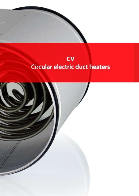
C I R C U L A R E L E C T R I C D U C T H E A T E R S<strong>CV</strong><strong>Circular</strong> <strong>electric</strong> <strong>duct</strong> <strong>heaters</strong>VEAB circular <strong>electric</strong> <strong>duct</strong> <strong>heaters</strong> are used for heating the ventilation air supplied to individual rooms andzones, with individually controlled temperatures. In correctly designed systems, they can also heat the entirebuilding. <strong>Circular</strong> <strong>electric</strong> <strong>duct</strong> <strong>heaters</strong> are also used for preheating or reheating for ventilation units. The <strong>duct</strong><strong>heaters</strong> are available with built-in electronic regulator or for external control. An electronic flow monitor isalso available, if required.<strong>CV</strong>• Seven sizes: 100 - 400 mm dia.• Output range 300 W – 12000 W• Tightness class C to EN 1751• A built-in electronic flow monitor is included in severalof the models• With built-in regulator or for external control• Two built-in overheating protections• Enclosed stainless steel plain-tube elementsStandard designThe casing is made of Aluzinc-coated sheet steel and theheater elements are made of stainless steel to EN 1.4301.The <strong>duct</strong> <strong>heaters</strong> conform to air tightness class C to EN1751. The junction box includes the necessary terminalblocks for the <strong>electric</strong>al connections. The <strong>duct</strong> connectionis suitable for insertion mounting in circular <strong>duct</strong>s.The <strong>CV</strong> is produced to degree of protection IP43, but isalso available to IP55 to special order (not the –MQU and–MTU versions).Overheating protectionAll <strong>CV</strong> <strong>heaters</strong> have two overheating protections, one ofwhich is with automatic reset and the other with manualreset. On delivery, these are connected in series with theheater elements and therefore need not be connected toan external relay (not the -E version; see page 13). Thisimproves reliability and lowers the installation costs.All <strong>duct</strong> <strong>heaters</strong> (not the -R version; see page 13) have theoverheating protection reset on the heater cover.Alarm relay, designation suffix –LAll models can be equipped with a built-in relay withpotential-free alarm contacts that indicate loss of powersupply or tripping of the manually resettable overheatingprotection.The alarm relay is included as standard inmodels –MQXL and –MTXL.Electronic flow monitorAll models with built-in control can also be supplied witha built-in electronic flow monitor. The flow monitorcontinually monitors the air flow and shuts down the heaterif the air velocity should drop below 1.5 m/s, thus avoidingoverheating. When the air velocity again exceeds 1.5 m/s,the heater will automatically be switched on. This meansthat the <strong>CV</strong> with built-in flow monitor meets therequirements for interlocking with the fan/air flow and canbe installed without any external interlocking. This ensuresvery simple installation.Air tightness class CThe <strong>CV</strong> <strong>duct</strong> heater conforms to air tightness class C,which ensures that the heated air will reach its destinationand will not leak out of the ventilation system – whichsaves energy and money.ApprovalsThe <strong>duct</strong> <strong>heaters</strong> have been tested and approved by SEMKO in accordance with:LVD Directive: EN 60355-1, EN 60335-2-30, SEMKO 111-1967 mod 1-4 and SEMKO 111 FA1982.EMC Directive: EN 50081-1, EN-50082-1, EN 61000-3-2 and EN 61000-3-3EMF Directive: EN 50366Page 2 | Chap. 1
CIRCULAR C R ELECTRIC E C DUCT HEATERSE ControlBuilt-in regulatorA built-in regulator ensures simple installation, e.g. dueto fewer cable runs, which lowers the installation cost andreduces the risk of incorrect wiring. The regulator iselectronic and controls the output across a triac by meansof time proportional control (intermittent ON/OFFcontrol). This provides very accurate temperature control.Since control is electronic, it is entirely silent and sustainsa minimum of wear.The following models are available with built-in regulator:External regulatorOur <strong>duct</strong> <strong>heaters</strong> can also be delivered without built-inregulator, and an external regulator must then be added.The following models are available for external regulator:-M(L), -E(L) and -R(L)An external temperature regulator and sensor must beprovided for the <strong>duct</strong> heater. See pages 12 and 13.<strong>CV</strong>-MQU(L) and -MTU(L), for one sensorDuct heater with built-in temperature regulator for room or<strong>duct</strong> sensor. The setpoint can be set on the heater cover orexternally. See page 6.-MQEM(L) and -MTEM(L), for two sensorsDuct heater with built-in temperature controller forexternal room sensor with setpoint adjuster. The minimumand maximum supply air temperatures are set on the <strong>duct</strong>heater circuit board. See page 8.-MQXL and –MTXL, for 0...10V control signalDuct heater with built-in regulator for external 0...10Vcontrol signal. See page 10.Options other than the standard versionIn addition to the standard design, several options are availablefor matching to your specific application.Other materialsThe casing can be made of stainless steel, EN 1.4301,or of stainless acid-proof steel, EN 1.4404.Anti-condensation insulationIn order to reduce the risk of condensation in the junctionbox if the <strong>duct</strong> heater is installed in a warm and humid areaand the air in the <strong>duct</strong> is cold, the inside of the junction boxis provided with additional 4 mm thick insulation.Degree of protection IP55To special order, the <strong>duct</strong> <strong>heaters</strong> can be made to degree ofprotection IP55 instead of the standard IP43 version(not -MQU and -MTU).Duct heater with an outlet temperaturehigher than 40°CAvailable only in a rectangular version with circular connection.See “Rectangular <strong>electric</strong> <strong>duct</strong> <strong>heaters</strong>”.Sizes larger than 400 mmAvailable only in a rectangular version with circular connection.See “Rectangular <strong>electric</strong> <strong>duct</strong> <strong>heaters</strong>”.Outputs higher than 12 kWAvailable only in a rectangular version with circular connection.See “Rectangular <strong>electric</strong> <strong>duct</strong> <strong>heaters</strong>”.Strengthened <strong>electric</strong>al insulationAvailable only in a rectangular version with circular connection.See “Rectangular <strong>electric</strong> <strong>duct</strong> <strong>heaters</strong>”.Chap. 1 | Page 3
C I R C U L A R E L E C T R I C D U C T H E A T E R SOverview of rangeSize designation <strong>CV</strong> 10 <strong>CV</strong> 12 <strong>CV</strong> 16 <strong>CV</strong> 20 <strong>CV</strong> 25 <strong>CV</strong> 31 <strong>CV</strong> 40Diameter (Ø mm) 100 125 160* 200 250 315 400 **Minimum air flow rate, m³/h 43 70 110 170 270 415 690RatingVoltage300 W 230V~ X 3 X 2400 W 230V~ X 3<strong>CV</strong>600 W 230V~ X 3 X 5 X 3 X 2 X 1900 W 230V~ X 7 X 4 X 2 X 2 X 11200 W 230V~ X 8 X 5 X 3 X 2 X 11500 W 230V~ X 9 X 6 X 3 X 3 X 21800 W 230V~ X 10 X 6 X 4 X 3 X 22100 W 230V~ X 7 X 4 X 3 X 22700 W 230V~ X 83000 W 230V~ X 6 X 4 X 3 X 23000 W 400V2~ X 6 X 4 X 3 X 23300 W 400V2~ X 95000 W 400V2~ X 12 X 8 X 6 X 4 X 36000 W 400V2~ X 9 X 7 X 4 X 35000 W 400V3~ X 126000 W 400V3~ X 9 X 7 X 4 X 39000 W 400V3~ X 9 X 6 X 412000 W 400V3~ X 10 X 7 X 5*= Also available with 150 mm dia. Delivered without rubber seals**=Also available with 355 mm dia. Delivered without rubber seals.1= See pressure drop curve 12= See pressure drop curve 23= See pressure drop curve 34= See pressure drop curve 45= See pressure drop curve 56= See pressure drop curve 67= See pressure drop curve 78= See pressure drop curve 89= See pressure drop curve 910= See pressure drop curve 1011= See pressure drop curve 1112= See pressure drop curve 12Pressure drop graphPaPressure dropAir velocitym/sPage 4 | Chap. 1
C I R C U L A R E L E C T R I C D U C T H E A T E R SInstallationThe <strong>duct</strong> <strong>heaters</strong> can be installed in either a horizontal or avertical <strong>duct</strong>. The air must flow through the <strong>duct</strong> heater inthe direction of the arrow shown on the <strong>duct</strong> heater. In ahorizontal <strong>duct</strong>, the junction box may face either upwardsor at 90° to either side. Installation with the junction boxat the bottom is not permissible. The distance to or froma <strong>duct</strong> bend, fan, damper or the like must be at least twicethe connection diameter.Minimum air velocity andoutlet air temperatureThe <strong>duct</strong> <strong>heaters</strong> are designed for a minimum air velocity of1.5 m/s and a maximum operating outlet air temperatureof 40°C (for higher temperatures, see “Rectangular <strong>electric</strong><strong>duct</strong> <strong>heaters</strong>”).Ambient air temperatures for <strong>duct</strong> <strong>heaters</strong>:Without built-in control equipment = 40°C max.With built-in control equipment = 30°C max.Interlock with fan/air flow rateElectric <strong>duct</strong> <strong>heaters</strong> must always be installed so that theyare interlocked either with the fan that delivers the air intothe <strong>duct</strong> or with the air flow rate through the heater. Thepower supply to the <strong>duct</strong> heater must be isolated if the fan/air flow is switched off.The -MQU, -MQEM and -MQXL models with built-inelectronic flow monitor conform to the requirement forinterlocking with the fan/air flow rate and can be installedwithout external interlocking.For other models, this function must be connected on theincoming power supply to the <strong>duct</strong> heater or, if the heaterhas a built-in regulator, directly to the regulator.The following formula can be used for calculating the airvelocity:V =A =Q3600 × Aπ × D²4Power demandThe air flowing through the <strong>duct</strong> heateris heated in accordance with the following formula:P = Q × 0.36 × ∆tV = air velocity, m/sQ = air flow rate, m³/hA = cross-section area of <strong>duct</strong> heater, m²D = diameter of <strong>duct</strong> heater, Ø mP = rating in WQ = air flow rate in m³/h∆t = temperature rise in °C<strong>CV</strong>Dimensions in mm278 Ø+1742 4282AIRØ375Setpoint adjustment (-MQU /-MTU)Resetting of manual overheating protectionChap. 1 | Page 5
<strong>Circular</strong> <strong>electric</strong> <strong>duct</strong> <strong>heaters</strong>with built-in control equipment for room or <strong>duct</strong> sensor<strong>CV</strong><strong>Circular</strong> <strong>electric</strong> <strong>duct</strong> heater with built-in control equipment fora room or a <strong>duct</strong> sensor<strong>CV</strong>The built-in control unit simplifies installation, e.g. by fewer cable runs. This, in turn, lowers the installationcost and reduces the risk of incorrect wiring.The <strong>duct</strong> heater operates with an external room or <strong>duct</strong> sensor. The temperature is set on the heater cover oron an external setpoint adjuster.- MQUDuct heater with built-in temperature regulator for room or<strong>duct</strong> sensor. The heater can be reset for external setpointadjustment or for setpoint adjustment on the heater cover.The -MQU model also has a built-in electronic flow monitorwhich simplifies the installation since it can be installed “standalone”.The sensor and the setpoint adjuster are available as separateaccessories.- MTUSame model as above but without built-in electronic flowmonitor.- MQUL and –MTULSame models as above but with built-in relay with potentialfreealarm contacts that indicate loss of power supply ortripping of the manually resettable overheating protection.Project design/orderingDescriptive text for – MQUVEAB type <strong>CV</strong> –MQU <strong>duct</strong> heater with casing ofAluzinc-coated sheet steel and stainless steel heaterelement to EN 1.4301. The <strong>duct</strong> <strong>heaters</strong> conform to airtightness class C to EN 1751. Built-in electronic flowmonitor. Control takes place by a built-in temperatureregulator for room or <strong>duct</strong> sensor. Setpoint adjustmenttakes place externally or on the heater cover. Thesensor and any external setpoint adjuster must beordered separately.Type designation(example)Descriptive text for – MTUVEAB type <strong>CV</strong> –MTU <strong>duct</strong> heater with casing ofAluzinc-coated sheet steel and stainless steel heaterelement to EN 1.4301. The <strong>duct</strong> <strong>heaters</strong> conform to airtightness class C to EN 1751. Control takes placeby a built-in controller for room or <strong>duct</strong> sensor.Setpoint adjustment is carried out externally or onthe heater cover. The sensor and any external setpointadjuster must be ordered separately.<strong>CV</strong> 16 - 50 - 2 MQULSize designation, see page 4Rating in watt x 100Voltage 1=230V~ 2=400V2~ 3=400V3~Type of control (-MQU/-MQUL/-MTU/ MTUL, see above)Page 6 | Chap. 1
<strong>Circular</strong> <strong>electric</strong> <strong>duct</strong> <strong>heaters</strong>with built-in control equipment for room or <strong>duct</strong> sensorAccessoriesThere are several sensor/setpoint combinations for the <strong>CV</strong> -MQU(L)/-MTU(L). Five typical cases are presented here.For particulars of sensors, see page 15. For a complete wiring diagram, see the fitting instructions at our homepagewww.veab.com (select Pro<strong>duct</strong>s/Duct <strong>heaters</strong> - Electric).Duct sensorAlt 1 Duct sensor with setpoint adjustment on the <strong>duct</strong>heater cover.Alt 2 Duct sensor with external setpoint adjustment.TG-K330 as <strong>duct</strong> sensor.TG-K330 as <strong>duct</strong> sensor.<strong>CV</strong>The setpoint is adjusted manually on the<strong>duct</strong> heater cover.TG-R430 as setpoint adjuster.Room sensorAlt 3 Room sensor with setpoint adjustment.Alt 4 Room sensor with external setpoint adjustment.TG-R430 both as setpointadjuster and room sensor.TG-R530 (IP30) or TG-R630 (IP54)as room sensor.TG-R430 as setpoint adjuster.Alt 5 Room sensor with setpoint adjustment on the <strong>duct</strong>heater cover.TG-R530 (IP30) or TG-R630 (IP54)as room sensor.The setpoint is adjusted manually on the<strong>duct</strong> heater cover.Chap. 1 | Page 7
<strong>Circular</strong> <strong>electric</strong> <strong>duct</strong> <strong>heaters</strong>with built-in control equipment for room CONTROL WITH MIN/MAX SUPPLY AIR TEMPERATUREAccessoriesThere are several sensor/setpoint combinations for the <strong>CV</strong> -MQEM(L)/-MTEM(L). Three typical cases are presented here.For particulars of sensors, see page 15. For a complete wiring diagram, see the fitting instructions at our homepagewww.veab.com (select Pro<strong>duct</strong>s/Duct <strong>heaters</strong> - Electric).Room sensorAlt 1 Room sensor with setpoint adjustment.TG-R430 as both setpoint adjuster and room sensor.<strong>CV</strong>TG-K360 <strong>duct</strong> sensor for min/max supply air temperature.Alt 2 Room sensor and separate setpoint adjustment.TG-R530 (IP30) or TG-R630 (IP54) as room sensor.TG-R430 as setpoint adjuster.TG-K360 <strong>duct</strong> sensor for min/max supply air temperature.Duct sensorAlt 3 Duct sensor with external setpoint adjustment.TG-K330 <strong>duct</strong> sensor as exhaust air sensor.TG-R430 as setpoint adjuster.TG-K360 <strong>duct</strong> sensor for min/max supply air temperature.Chap. 1 | Page 9
<strong>Circular</strong> <strong>electric</strong> <strong>duct</strong> <strong>heaters</strong>with built-in control equipment for external 0...10V control signal<strong>CV</strong><strong>Circular</strong> <strong>electric</strong> <strong>duct</strong> heater with built-in control equipment forexternal 0...10V control signalThe built-in control unit simplifies installation, e.g. by fewer cable runs. This, in turn, lowers the installationcost and reduces the risk of incorrect wiring.<strong>CV</strong>- MQXLDuct heater with built-in control eqipment for 0...10Vcontrol signal.The -MQXL model also has a built-in electronic flowmonitor which simplifies the installation since it can beinstalled “stand alone”.The heater has a built-in relay with potential-free alarmcontacts that indicate loss of power supply or tripping of themanually resettable overheating protection.- MTXLSame model as above but without built-in electronic flowmonitor.Project design/orderingDescriptive text for – MQXLVEAB type <strong>CV</strong> –MQXL <strong>duct</strong> heater with casing ofAluzinc-coated sheet steel and stainless steel heaterelement to EN 1.4301. The <strong>duct</strong> <strong>heaters</strong> conform to airtightness class C to EN 1751. Built-in electronic flowmonitor and built-in relay with potential-free alarmcontacts that indicate loss of power supply or trippingof the manually resettable overheating protection.Control takes place by a built-in regulator for external0...10V control signal.Type designation(example)Descriptive text for –MTXLVEAB type <strong>CV</strong> –MTXL <strong>duct</strong> heater with casing ofAluzinc-coated sheet steel and stainless steel heaterelement to EN 1.4301. The <strong>duct</strong> <strong>heaters</strong> conform toair tightness class C to EN 1751. Built-in relay withpotential-free alarm contacts that indicate loss ofpower supply or tripping of the manually resettableoverheating protection. Control takes place by a builtinregulator for external 0...10V control signal.<strong>CV</strong> 16 - 50 - 2 MQXLSize designation, see page 4Rating in watt x 100Voltage 1=230V~ 2=400V2~ 3=400V3~Type of control (-MQXL/-MTXL; see above)Page 10 | Chap. 1
<strong>Circular</strong> <strong>electric</strong> <strong>duct</strong> <strong>heaters</strong>with built-in control equipment for external 0...10V control signalControl with accessoriesThere are several ways of controlling a <strong>CV</strong> -MQXL/-MTXL. Three examples are presented here.For a complete wiring diagram, see the fitting instructions at our homepage www.veab.com(select Pro<strong>duct</strong>s/Duct <strong>heaters</strong> - Electric).Master system<strong>CV</strong>0...10VVentilation unit that has built-in control with a 0...10V output for a reheater coil0...10V0...10V regulator control0...10VChap. 1 | Page 11
<strong>Circular</strong> <strong>electric</strong> <strong>duct</strong> <strong>heaters</strong>f o r e x t e r n a l c o n t r o l e q u i p m e n t<strong>CV</strong><strong>Circular</strong> <strong>electric</strong> <strong>duct</strong> heater for external control equipmentVEAB <strong>electric</strong> <strong>duct</strong> <strong>heaters</strong> for external control must be equipped with an external temperature regulator.These can be mounted on a wall or in an equipment cubicle. Regulators and sensors must be ordered separately(see pages 14 and 15).<strong>CV</strong>- MSuitable control by PULSER or TTC type regulator.The overheating protection is reset manually on the <strong>duct</strong>heater cover.Ratings up to and including 9000 W.- MLSame model as above but with built-in relay with potentialfreealarm contacts that indicate loss of power supply ortripping of the manually resettable overheating protection.Project design/orderingDescriptive text for – MVEAB type <strong>CV</strong> –M <strong>duct</strong> heater with casing of Aluzinccoatedsheet steel and stainless steel heater elementto EN 1.4301. The <strong>duct</strong> <strong>heaters</strong> conform to airtightness class C to EN 1751. Control takes place by anexternal regulator and sensor that must be orderedseparately.Type designation(example)Descriptive text for – MLVEAB type <strong>CV</strong> –ML <strong>duct</strong> heater with casing of Aluzinccoatedsheet steel and stainless steel heater elementto EN 1.4301. The <strong>duct</strong> <strong>heaters</strong> conform to air tightnessclass C to EN 1751. Built-in relay with potential-freealarm contacts that indicate loss of power supplyor tripping of the manually resettable overheatingprotection. Control takes place by an externalregulator and sensor that must be ordered separately.<strong>CV</strong> 16 - 50 - 2 MLSize designation, see page 4Rating in watt x 100Voltage 1=230V~ 2=400V2~ 3=400V3~Type of control (-M/-ML; see above)Page 12 | Chap. 1
<strong>Circular</strong> <strong>electric</strong> <strong>duct</strong> <strong>heaters</strong>f o r e x t e r n a l c o n t r o l e q u i p m e n t<strong>CV</strong><strong>Circular</strong> <strong>electric</strong> <strong>duct</strong> heater for external control equipmentVEAB <strong>electric</strong> <strong>duct</strong> <strong>heaters</strong> for external control must be equipped with an external temperature regulator.These can be mounted on a wall or in an equipment cubicle. Regulators and sensors must be ordered separately(see pages 14 and 15).- RThe built-in manual overheating protection is manuallyreset remotely by an external type RSI/RSU reset buttonwith indicating lamp.The lamp will light up when the overheating protection hastripped.For 230V, a PULSER 220 R can be used which, in additionto the ordinary control functions, also has a built-in resetbutton and indicating lamp.For 400V, a PULSER or TTC and an external RSI/RSUreset button are used.<strong>CV</strong>- ESuitable control by type TTC regulator.The built-in manual overheating protection is reset onthe <strong>duct</strong> heater cover. The overheating protections aresingle-pole and must be connected to an external operatingcircuit.Rating of 12000 W.Project design/orderingDescriptive text for – RVEAB type <strong>CV</strong> –R <strong>duct</strong> heater with casing of Aluzinccoatedsheet steel and stainless steel heater elementto EN 1.4301. The <strong>duct</strong> <strong>heaters</strong> conform to air tightnessclass C to EN 1751. Control takes place by an externalregulator and sensor that must be ordered separately.Descriptive text for – EVEAB type <strong>CV</strong> –E <strong>duct</strong> heater with casing of Aluzinccoatedsheet steel and stainless steel heater elementto EN 1.4301. The <strong>duct</strong> <strong>heaters</strong> conform to air tightnessclass C to EN 1751. Control takes place by an externalregulator and sensor that must be ordered separately.Type designation(example)<strong>CV</strong> 16 - 50 - 2 RSize designation, see page 4Rating in watt x 100Voltage 1=230V ~ 2=400V2~ 3=400V3~Type of control (-E/-R; see above)Chap. 1 | Page 13