Download - Olimex
Download - Olimex
Download - Olimex
- No tags were found...

Create successful ePaper yourself
Turn your PDF publications into a flip-book with our unique Google optimized e-Paper software.
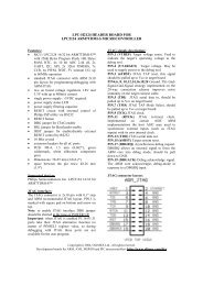
ICSP connector layout:The ICD/ICSP connector is 6 pin with 0,1" step.It may be used to program other boards withPICs via PIC-PG4D. The PIN.1 is marked withsquare pad on bottom and arrow on top. ICSPsignals are: 1- MCLR, 2- VDD, 3- VSS/GND, 4-PGD/RB7, 5- PGC/RB6, 6- PGM/RB3.ICSP programming:Please note that in your target circuit MCLRshould be not directly connected to VCC, asprogrammer try to rise MCLR to 13VDC to enterin programming mode. If MCRL on target boardis connected to VCC and you attempt to do ICSPprogramming you may destroy PIC-PG4Dprogrammer.Ordering codes:PIC-PG4D-84PIC-PG4D-628- assembled and tested withPIC16F84A microcontroller- assembled and tested withPIC16F628 microcontrollerCopyright(c) 2003, OLIMEX Ltd, All rights reserved.Development boards for PIC, AVR and MSP430 microcontrollers http://www.olimex.com/dev