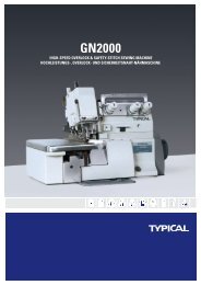
GC6-6 6-7è±æ.cdr - Typical
GC6-6 6-7è±æ.cdr - Typical
GC6-6 6-7è±æ.cdr - Typical
- No tags were found...
Create successful ePaper yourself
Turn your PDF publications into a flip-book with our unique Google optimized e-Paper software.
6. Adjustment7. Periodical cleaning8. Troube-shooting……………………………………………………………………………………………136.1 Timing between needle and rotating hook motion ……………………………………………………… 136.1.1 Adjusting the needle bar position…………………………………………………………………………146.1.2 Adjusting rotating hook point timing with needle ……………………………………………………… 146.1.3 Removing and installing the rotating hook ……………………………………………………………… 146.1.4 Adjusting the clearance between rotating hook and bobbin caseholder position bracket ………………………………………………………………………………… 146.2 Adjusting the feed dog …………………………………………………………………………………… 156.2.1 Adjusting height of feed dog …………………………………………………………………………… 156.2.2 Adjusting the position of feed dog ……………………………………………………………………… 156.3 Adjusting the tension releasing mechaninsm ………………………………………………………… 156.4 Adjusting the pressure of presser foot …………………………………………………………………… 166.5 Adjusting top feed mechanism …………………………………………………………………………… 166.5.1 Adjusting top feed mechanism of machine Model <strong>GC6</strong>-6 ………………………………………… 16~176.5.2 Adjusting the feed mechanism of machine Model <strong>GC6</strong>-7 ………………………………………… 17~18………………………………………………………………………………… 19……………………………………………………………………………………… 20Parts Manual1. Model <strong>GC6</strong>-6 arm and bed2. Model <strong>GC6</strong>-7 arm and bed………………………………………………………………… 21~22…………………………………………………………………23~2425~26…………………………………………27~28…………………………………………29~30……………………………………………………………… 31~32………………………………………………………………… 33~34……………………………………………………………………… 35~3637~38………………………………………………………………………………………39~40…………………………………………………………………41~42………………………………………………………………… 43~44……………………………………………………………………… 45~46……………………………………………………………………… 47~4849~50………………………………………………………………………………………3. Model <strong>GC6</strong>-6 needle bar and thread take-up4. Model <strong>GC6</strong>-7 needle bar and thread take-up5. Arm shaft and vertical shaft6. Rotating hook and its shaft7. Stitch length regulating8. Bottom feed9. Model <strong>GC6</strong>-6 presser bar10. Model <strong>GC6</strong>-7 presser bar11. Model <strong>GC6</strong>-6 top feed12. Model <strong>GC6</strong>-7 top feed13.Lubrication14.Drip pan and knee lift15. Accessories………………………………………………………………………………………………………………………………………………………………
3. Installation and preparation3.1 Installation3.1.1 Location of the machineTo ensure a smooth running, the machineShould be located on rigid and flat floor.The insertof rubber mat between machine stand and floor isrecommended for further reducing the runningnoise and vibration.3.1.2 Installing drip pan(Fig.1)Fix drip pan 1into the table cutout, aligningknee lifter lifting rod 3 with knee lifter connectingrod 15 of machine head, and to touch it, alsomaintain dimendions 30 and 119.5mm from nailhole to the table, then drive nails into bothsides of the cutout to secure the drip pan.(furthersee figure on page56).3.1.3 Mounting machine head(Fig.2)Make the hinge A of machine head engagedwith hinge socket B on the table, then turn themachine head freely till it is seated on the frameof table cutout.B153119.513012A3.1.4 Mounting rock shaft bracket of knee liter(Fig.3, also see figure on page 56)1) Adjust rock shaft knee plate 18 according tothe body of operator,for the convenience to operate.2) Adjust the position of knee lifter assemblyaccording to Fig. 3, then fasten the rock shaftbracket with wood screws 6.1115293132.5119.5268367182
A43.1.5 Installing the motor(Fig.4)Align machin balance wheel belt groove A withmotor pulley belt groove B by moving the motor Cleftward or rightward. Be sure the belt is not touchwith table.CorrectBCincorrectGFEDCBA10 ~ 12mm20-3053.1.6 Connecting the clutch lever to the pedal (Fig.5)1) The optimum tilt angle of pedal A withfloor is approx. 15 degree.2) Adjust the clutch of the motor so thatclutch lever C and draw bar B run in line.3) The machine balance wheel should rotatecounterclockwise for normal sewing when viewfrom opposite side of balance wheel G. Themotor is rotation in the same direction.The rotationcan be reversed by reversing (turn over 180 deg.)The plug of motor.4) Adjust the tension of V-belt F by movingthe motor vertically. The proper tension of V-beltis a salck of 10-12mm when the belt is depressedat the belt span by finger.EDCBAD63.1.7 Installing the bobbin winder(Fig.6)Align pulley B of bobbin winder with outsideof belt and should be kept a proper clearancebetween them, so that pulley B could be contactedwith belt after the stop latch thumb.lever A depressed, thereby belt drives the pulleyB while machine running. After check bobbinwinder is in parallel with belt slit E of table,fastened by two wood screws D.3
3.1.8 Installing the thread unwiner (Fig.7)Locate thread unwinder at the right front ofthe table, note that spool rest may not obstructwhen machine head is turned backward, thentightern wood screw C.73.2 Preparation3.2.1 Cleaning the machineBefore delivery , the machine parts arecoated with rust preventive grease, which may behardened and contaminated by dust during storageand shipment. This grease must be removed byclean cloth with gasoline.3.2.2 ExaminationThough every machine is confirmed by strictinspection and test before delivery,the machine partsmay be loosed or deformed after long distancetransportation with jolt. A thorough examinationmust be performed after cleaning the machine.Turn the balance wheel to see if there is runningobstruction, parts collision, uneven resistance orabnormal noise. If these exist, adjustment must bemade accordingly before run.3.2.3 LubricationBefore machine running, Clean it with softcloth, then fully lubricate the holes indicated byarrows shown in Fig8 .If the machine is in contionus operation, theoperator should lubricate it no less than twotimes a days.Be sure to use HA-8 Sewing Machine Oilor HJ-7 Machinery Oil.C8A8B4
8BModel <strong>GC6</strong>-6Presser footlift, front crank8CANutModel <strong>GC6</strong>-7oil return felt8EFor vaccum sucking needle bar inside oil, see Fig8E.A long oil-return felt should be installed.Hook oil store is not filled with lubrication oilbefore leaving off the factory. fill oil before use.oil store5
A9Oil Hole A up to PartF. G. H. I. J(See Fig9).JIHGF10Oil Hole B up to PartC. D. E(See Fig10)throughB9 oil wick.CDEK11The bevel gear cases in Fig. 11 and Fig.12 arepacked with grease, which should be replenishedperiodically as may be consumed gradually afterlong time of operation . When replenish, turn offscrew plugs L,K first and packed with fresh greasethru screw hole into gear cases then screw on screwplugs. Should the grease in the bevel gear casesbeen too dirty or partial hardened, it must bechanged thoroughly6
3.2.4 Trial runTrial run is required for a new sewing machine,or when the machine left out operation forconsiderable length of time is used again.Before the trial run , lift presser foot first, thebalance wheel must be rotated in correct directionas mentioned in 3.1.6,3 ). Run the machine beginat a low speed, as the machine runs well thenincreasing the speed gradually and up to 2000spm,after a few minutes to stop the machine for examination.As the machine is run sufficiently well thenput it into operationL124. Operation4.1. Selection of threadNeedle thread should be left-twisted. Thread. Forbobbin thread, either left or right twisted thread isavailable.To identify the twist direction of the thread, holdthe thread as shown in Fig.13, twist the thread byright hand in the direction of arrow. If the strandturn to be tight,the thread is the left-twisted, otherwisethe thread is right- twisted thread .4.2 Coordination between needle, thread andsewing materialNeedle of machine Model <strong>GC6</strong>-6 is Dp 17,#18-#22Needle of machine Model <strong>GC6</strong>-7 is Dp 17,#18-#22Selection to the needle size should be based uponthe thread and material to be sewn.The following table is for referenceNeedleSize Kind and number of thread Material to be sewn#18#19#21~#22Cotton thread #30-#40Linen thread #60-#80Polyester thread #20-#40linen thread #40-#60clothes, canvas heavy woolheather cloth, shoes, cap, hand bagHeavy fabric,leather goods,glazed thread #40-#60 sofa, suitcase, bag,mercerized thread#21-#60 tarpaulin, cushion137
I144.3 Installing the needle (Fig.14)Turn the balance wheel to lift needle bar to thehighest position, loosen needle set screw 1, fully insertthe needle shank upto the bottom of needle socket, thentighten needle set screw 1.Note: Fig.14(b): insufficient insertion,Fig.14(c): wrong direction of long groove.Neelde long grooveClearanceabcFG21EDCBA154.4 Winding the Bobbin thread4.4.1 Winding method (Fig. 15)1) Install bobbin A to bobbin winder spindle B.2) Pass thread C from spool through the eye 1on tension bracket E. Pass it between tension discs2, and then wind the end of the thread a few turnson the bobbin3) Push stop latch thumb lever D down to lock thebobbin, the winder pulley F is thereby pressed on belt G.4) Start the machine to wind thread.Note when thread is wound without sewingoperation, be sure to keep the presser foot lifted.5) When thread is fully wound the bobbinwinder stop latch automatically release the bobbinwinder, thus stopping the winding motion.8
4.4.2 Winding adjustment(Fig.16)1) Wound bobbin thread should be neat and tight,if not, adjust the thread tension by turning tensionstud thumb nut A of bobbin winder tension bracket.Note: nylon or polyester thread should be woundwith light tension, otherwise bobbin D might bebroketn or deformed.2) When the wound thread layer does not presenta cylindrical shape as in Fig.16a, loosen tensionbracket screw B and move tension bracket Cleftward or rightward. If thread is wound asshown in Fig, 16b, move the tension bracketrightward, while if thread is wound as shown inFig. 16c, move the tension bracket leftward, Afteradequately positioning the tension bracket, tightenscrew B.Donot over fill the bobbin,the optimum capacityof thread will fill about 80% of bobbin outsidediameter, this can be adjusted by stop latch screw E.4.5 Threading the needle thread and drawing thebobbin threadTo thread the needle thread, raise needle bar toits highest position, lead the thread from spool andpass it in the order numerically instructed in Fig.17.The detail of threading are as follows:1) Lead thread from spool, pass down thru theright side of thread guide plate 1, to left pass up thrumiddle hole o f thread guide plate 1,to left pass thrubetween two small tension discs and pass down thruthe left hole of thread guide plate 1.2) To left pass down thru the right hole, to leftup thru middle hole and to left down thru left hole ofthread retainer 2.3) Pass down thru between two tension discs, toleft and up pass thru the hook of thread take-up spring,turn to left pass thru underneath the slack threadregulator5 (Model <strong>GC6</strong>-7 is the thread guide), then uppass thru the thread guide 6. and up to left pass thruthe hole of thread take-lever 7.4) Turn down to left pass thru the thread guide 8,pass down thru the therad guard 9 of needle bar bushing(lower)(on the machine Model <strong>GC6</strong>-7 is the lowerthread guard 9) and needle bar thread guide 10. Thenpass the thread from left thru the eye of needle 11,afterward draw out the thread from needle eyeapprox 100mm.To draw the bobbin thread, hold the tip of theneedle thread by hand,turn the balance wheel to lowerthe needle bar and then, to lift it to its highest position.Pull the needle thread and then the bobbin thread isdrawn up. Put the tips of needle and bobbin threadtoward from under presser foot.4.6 Setting the bobbin (Fig.18)1) Put bobbin B into bobbin case A.2) Pass the thread thru slit C to lead it underneaththe bobbin case tension spring D and out at the notchof spring, draw out thread about 100mm.3) Make sure that the bobbin rotates clockwisewhen the thread E is drawn, if not ,reverse the bobbin B.9791011ABa b c d28C546DE31ABCDE161718
ABCD194.7. Installing the bobbin case (Fig.19)1) Lift the needle bar to its hightest position andopen the bed slide.2) Fully lift bobbin case latch lever A and holdingit by fingers, securely install the bobbin case into therotating hook B.Note that the bobbin case latch is engagedin the positioning groove of rotating hook spindle.3) When remove the bobbin case from rotatinghook,fully lift the bobbin case latch lever A and holdingit by fingers first, so that to prevent the bobbin fromdropping out from the bobbin case, then gently takethe bobbin case out.1 2204.8. Setting stitch length and reverse sewing (Fig.20)1) Stitch length can be set by turning stitch lengthregulating dial 1.The stitch length is longer when turningstitch length regulating dial 1counter-clockwise, and thestitch length is shorter when turning the dial 1 clockwise.2) Sewing reverse when feed reverse lever 2 isdepressed, and forward sewing is restored automaticallywhen release the depressing on feed reverse lever 2StrongAweak21 5. Adjusting thread tensionIn principle the thread tension is to be adjusted inaccordance with materials, thread and other factors.In practice, the thread tension is adjusted accordingto the stitches resulted. The needle thread tensionshould be adjusted with referensce to the bobbin threadtension.To adjust the bobbin thread tension, turn bobbincase tension spring screw A (see Fig.21) clockwise toincrease the tension,or turn the screw counter-clockwiseto decrease the tension.10
It is a common practice to check the bobbinthread tension as shown in Fig. 22. In case of glazedthread #50, hold the end of pulled out thread and tovibrate bobbin case up and down, if the bobbin casefall down slowly, the proper tension is obtained.The needle thread tension can be adjusted bychanging:(1) tension of the thread take-up spring,(2) swinging range of the thread take-up spring,(3) tension of tension disc(4) the position of thread guide 6 in fig. 17. Allthese adjustments will be described as follows.ABBobbin225.1. Adjusting the thread take-up springThe normal tension of thread take-up spring is approx.35-55. The normal swing range of the thread take - upspring is 5-8mm. For sewing light weight materials (withshort stitch length), weaken the spring tension and widenthe swinging range of spring, while for sewing heavyweight materials, strengthen the spring tension andshorten the swinging range of spring.5.1.1 Adjusting the thread take-up spring tension(Fig.23)Loosen tension stud set screw A, turn tension stud Bclockwise to increase the spring tension, or turn thetension stud counter-clockwise to decrease the springtension. After the adjustment, be sure to tighten tensionstud set screw A.The thread take-up spring tension is about 45g. Toattain this, loosen set screw A first, then turn tension studB counter clockwise to release the tension of thread takeupspring C to zero, and turn tension stud Bclockwise until spring C just comes into contact with thestopper on thread take-up spring regulator, then furtherturn tension stud B clockwise be 1/2 turn. After adjustme-nt, tighten tension stud set screw A.5.1.2 Adjusting the swing range of thread take-upspring (Fig.24)Loosen set screw B, turn tension complete Cclockwise to increase the swing range or turn tensioncomplete C counter-clockwise to decrease the swingrange. After the adjustment, tighten set screw B.Before delivery, thread take-up spring is properlyadjusted. Re-adjustment is needed only in the case ofsewing special material material or with special thread.5 ~8mmBCCBA232411
245.2 Adjusting the thread guideThe position of thread guide affects sewing qualityand therefore must be adjusted according to the materialsto be sewn and sewing conditions.The normal relationship beween the position ofthread guide (Fig.17) and the materials to be sewn is asthe following table1 2 35 ~8mmBCThreadguidePositionLeftward Center RightwardMaterialweightHeavy Medium Lightabcde255.3 Adjusting the tension of needle thread and bobbinthreadFig.25 shows the various type of stitch formsprobably to happen when sewing.Normal stitch form should be as shown in Fig.25 (a).When abnormal stitches occur with puckering, loosestitch or thread breakage, the tension of needle threadand bobbin thread must be adjusted accordingly.12
1) In case of needle thread tension is too strong orbobbin thread tension is too weak, as shown inFig.25(b), turn the tension regulating thumb nut counterclockwiseto decrease the needle thread tension or tightenthe bobbin case tension regulating screw to increase thebobbin thread tension(see Fig. 26).2) In case of needle thread tension is too weak orbobbin thread is too strong as shown in Fig.25(c), turnthe tension regulating thumb nut clockwise to increasethe needle thread tension or turn the bobbin case tensionregulating screw counter-clockwise to decrease the bobbinthread tension (see Fig. 27).3) In case of stitches as shown in Fig. 25(d), (e),adjustment can be made with reference to above means.26276. Adjustment6.1 Timing between needle and rotating hook motion6.1.1 Adjusting the needle bar position(Fig. 28)1) Turn the balance wheel to locate needle bar atits lowest position.2) Remove face plate (or rubber plug).3) Loosen needle bar connecting stud clampingscrew A.4) Move needle bar vertically to bring the center ofneedle eye D coincidence with inside surface E ofbobbin case holder.5) Then tighten clamping screw A.ADE2813
CDE1.2 mm296.1.2 Adjusting rotating hook point timing with needle(Fig. 29)Turn the balance wheel to locate needle bar to itslowest position, and when needle bar lifted again at 2.5mmfrom its lowest position, the rotating hook point D shouldbe coincides with needle center line C, and hook point Dis 1.2 mm above the upper edge E of needle eye.2.5mmD30When adjusting the rotating hook point timing also notethat clearance between notch bottom of needle D andhook point C must be maintained approx.0.05mm (see Fig.30)CBA0.05mm0.05-0.7mmCD316.1.3 Removing and installing the rotating hook (Fig. 31)1) Lift the needle bar to its highest position.2) Remove the throat plate, take down the needleand the bobbin case.3) Loosen rotating hook bobbin case holder positionbracket screw C and take down position bracket .4) Loosen two set screws D of rotating hook.5) At this point, the rotating hook can be turned freelyon its shaft, and it can be kept to avoid the collision withfeed dog support as the feed dog support in its highest,then take down the rotating hook slowly.6) Installing the rotating hook can be done in reversesequence.6.1.4 Adjusting the clearance between rotating hookand bobbin case holder position bracket (Fig.31)The projecting flange of the position bracket A shouldbe engaged in the notch B of the bobbin case holder, andmaintain a clearance of 0.5-0.7 mm between projectingflange top and the bottom of notch while installing.14
6.2 Adjusting the feed dog6.2.1 Adjusting height of feed dog32Turn balance wheel to raise the feed dog to itshighest position, at that position, the height of feeddog teeth should be projected 0.8-1mm above throatAB0.8mm~1.2mmplate top surface as shown in Fig.32. The height offeed dog teeth of 1mm above the throat plate topsurface can be taken while sewing heavy material.33When adjusting, loosen feed lifting rock shaftcrank clamping screw A (Fig.33) slightly, then turnAfeed lifting rock shaft crank B till the proper heightof the feed dog teeth is achieved, after adjustment,tighten clamping screw A.B6.2.2 Adjusting the position of feed dog (Fig.34)The standard position of feed dog A is that theclearance from the throat plate slit end to the frontend of the fully advanced feed dog is 1.5 mm. asshown in Fig.34a1.5mmA341) Fix the feed dog in the position where thefeed fully advances.2) Loosen two feed rock shaft crank clampingscrews B slightly, as shown in Fig.34b3) Move feed bar to adjust the clearance betweenFeed rockshaft crankthe feed dog and throat plate.4) After adjustment, tighten clamping screw B .B6.3 Adjusting the tension releasing mechanism(Fig.35)The tension discs should be pushed apart to openwhen the presser foot is lifted. But the open timing ofthe tension discs can be adjusted as follows:.1) Remove face plate and the rubber plug at rearside of arm and lossen screw A of the knee liftinglever (left).2) Then the tension releasing cam can be movedleftward or rightward, open later when the cam ismoved rightward, open earlier when the cam ismoved leftward.3) After adjustment, tighten screw A and replacerubber plug and face plate.Screw driverRubber plugScrewLeftPresser ber lifterRight35Thread tension releasing camThread tension releasing rodTension15
6.4 Adjusting the pressure of presser foot (see Fig.36)pressure on presser foot is to be adjusted in accordancewith material to be sewn.Loosen lock nut B,b, first, then turn pressure regulatingthumb screwA,a,clockwise as shown in Fig.36 toincrease the pressure while turn the pressure regulatingthumb screw A ,a, counter-clockwise to decrease thepressure on presser foot, then tighten lock nut B,b,BAabABa36b6.5 Adjusting top feed mechanism6.5.1 Adjusting top feed mechanism of machine Model<strong>GC6</strong>-61) Adjusting feed amountThe top feed can be adjusted to synchronize withbottom feed or differential with bottom feed.Loosen the nut with a spanner, then change the centerdistance A, as shown in Fig.37a. Increase distance A toincrease the top feed amount, decrease the center distanceto decrease the top feed amount, after adjusting, tightenthe nut. Trial sewing should taken after every adjustment.The adjusting is repeated if necessary, until the requiredfeed style is achieved.2) Adjusting the alternate lift amount of the presser feetThe lift amount of the walking presser foot is with5.5 mm when sewing medium or heavy material, and thepresser foot lift amount is 3.5 mm.The lift amount of thesetwo presser feet can be changed slightly according to thenature of material or the requirements in sewing. But hesum tof these two presser feet lift amount is nearly thesame, as the other mechanisms are kept in constantconditions. In other works, the increasing of walkingpresser foot lift amount will diminishes the lift amount ofpresser foot, and vice versa.When adjusting, loosen clamping screw of presser footlift front crank slightly with a screwdriver and turn the crankto overcome the friction on its shaft, as shown in Fig.37a.The lift amount of walking presser foot can be increasedand the lift amount of presser foot is decreased if turn thecrank clockwise.The lift amount of walking presser foot isdecreased and the lift amount of presser foot is increasedwhen turn the crank counter-clockwise. After adjustmenttighten the clamping screw.ANutPresser footlift front crank37a16
3) Adjusting the lift amount of presser foot togetherwith walking presser footThe lift amount of walking presser foot together withpresser foot also can be adjusted slightly. When adjusting,loosen nut with a spanner first, then move the presser foot liftregulating screw to change its center distance B between thepresser foot lift shaft, as shown in Fig.39 The lift amount isincreased as to shorten the center distance B, and the liftamount is decreased when widen the center distance B,After adjustment, tighten the nut again.4) Adjusting the clearance betwesser foot and walkingpresser footIn sewing operation, for prevent the walking presser footfrom striking on presser foot at the end of feeding, a properclearance C of approx. 1.5mm should be maintained betweenthem, as shown in Fig.40b. When the clearance is too smallor too big necessary to adjust, loosen rear crank clampingscrew with a screw driver and turn the rock shaft, sa shown inFIG.40A. Turn rock shaft clckwise to decrease the clearance C,and turn the rock shaft counter clockwise to increase theclearance C. After adjustment, tighten clamping screw.After the adjustment of 2).3) or 4) as mentioned above, aninspection should be made, as to raise the presser feet withpresser bar lift, and turn balance wheel slowly to see that thewalking presser foot is to strike with other parts, if it is, shouldbe adjusted again.AboveUnderNutPresser footlift front crank37b6.5.2 Adjusting the feed mechanism of machine Model <strong>GC6</strong>-71) adjusting the feed amountTop feed must be synchronized with needle feed andbottom feed, this is performed in factory before delivery. Ifnecessary it can be adjusted as follows:Lift the presser foot with presser bar lifter, set the maxstitch length, then turn balance wheel slowly and watch forneedle penetration to see if the needle is positioned in thecenter of feed dog needle hole, at the point B as show inFig.38, if not, should be adjusted first as shown in Fig.40a.After adjustment, tighten the clamping screw.Turn the balance wheel continuously until the needlefeed end is reached, at that time, the feed amount is correctwhen the needle is still positioned in the center of feed dogneedle hole, at the point B1 as shown in Fig.38. If theneedle is positioned at point A in Fig.38, the feed amount istoo big, and too small of feed amount while the needle ispositioned at point C in Fig.38, all of these should beadjusted accordingly. In adjusting, loosen nut with a spanner,then to change the center distance A, after adjustmenttighten the nut.ForwardABCBStitch lengthNeedle3817
B2) Adujsting the alternate lift amount of the presser feetLift amount of the walking presser foot is within 5mmand lift amount of the presser foot is 2.5 mm, when sewingmedium or heavy materials. The lift amount of these twopresser feet can be changed slightly according to the natureof material or the requirements in sewing. The sum of thelift amount of these two presser feet is nearly the same asthe other mechanisms are kept in constant condition .Inother words, the increasing of walking presser foot liftamount diminishes the lift amount of presser foot, and viceversa.When adjusting, loosen the presser foot lift front crankclamping screw slightly with a screw driver as shown inFig.37b, and turn the crank to overcome the friction on itsshaft. The lift amount of walking presser foot can beincreased and the lift amount of presser foot is decreased ifturn the crank clockwise. The lift amount of walking presserfoot is decreased and the lift amount of presser foot isincreased when turn the crank counter-clockwise. Afteradjustment, tighten the clamping screw.3) Adjusting the lift amount of presser foot together withwalking presser footThe lift amount of presser foot together with walkingpresser foot can be adjusted slightly. When adjusting, loosennut with a spanner foot lift regulating screw to change itscenter distance between the presser foot lift shaft as shownin Fig.39. The lift amount is increased as to shorten thecenter distance B, and the lift amount is decreased when towiden the center distance B. After adjustment, tighten thenut again.4) Adjusting the clearance between presser foot andwalking presser footIn sewing operation, for prevent the walking presser footfrom striking on presser foot at the end of feeding, a properclearance C of approx. 1.5mm should be maintained betweenthem, as shown in Fig.40c. When the clearance is too smallor too big necessary to adjust, loosen rear crank clampingscrew with a screw driver and then turn the rock shaft asshown in Fig.40a. Turn the rock shaft clockwise to increasethe clearance C, and turn the rock shaft counter-clockwise todecrease the clearance C. After adjustment, tighten theclamping screw.After adjusting the clearance between presser foot, it isprobable the needle to deviate from the center of the feeddog needle hole in feed direction, this can be adjusted toloosen the feed rock shaft crank clamping screw B (Fig.34b) and shifting the feed dog B (Fig.40d) in direction offeed after adjustment, tighten clamping screw B again, Incase the needle is deviated from the feed dog needle holecenter in the crosswise direction, loosen twoo feed dog screwA (Fig.40d) and to shift the feed dog B crosswise. Afteradjustment, tighten the feed dog screw.After the adjustment of 1)-4) as mentioned above, aninspection should be made, as to raise the presser foot withpresser bar lifter and turn the balance wheel slowly to seethat the walking presser foot is to strike the other parts. If itmay be, should be adjusted again.NutAPresser foot lift shaftPresser foot liftregulating screwBCrear crankClamping screwneedle bar vibrating shaftABCC394018
417. Periodical cleaning7.1. Cleaning the feed dog(Fig.41)Remove the throat plate and clean off all the dustand lint on the feed dog.Feed dogRotating hook427.2 Cleaning the rotating hook(Fig.42)Lay down the machine head and clean the hook,wipe the bobbin case with soft cloth.Rotating hookFeed bar19
8.Trouble shootingTrouble Possible causes RemedyNeedlebreakingSkipstitch1. Needle too thin or bent.2. Wrong set of needle.3. Push or pull the materialwith hand while sewing.4. Too heavy the weight ofsewing material.1. Needle bent or needlenumber is not fitted theweight of material.2. Wrong set of needle.Change the needle with newone.Refer to the section 4.3.Support the material gentlywith hand while sewing.Sewing according to thetechnical specificationChange the needle.Refer to the section 4.3.NeedlethreadbreakingBobbinthreadbreakingLoosestitchPuckering1. Wrong needle threading.2. Needle thread tension toostrong.3. Poor thread.4. Needle too thin or toorough.1. Too strong the bobbinthread tension.2. Thread wound on bobbinflabbily and uneven.3. Needle hole of throatplate too rough or haveworn.1. Unsuitable adjust ofneedle thread tension andbobbin thread tension .2. Too weak the tension onthread take-up spring.1. Too light the weight ofmaterial and too long thestitch length.2. Too strong the threadtension on needle andbobbin.3. Too strong the pressureon presser foot.Refer to the section 4.5.Refer to the section 5.3.Change the thread.Change the needle.Weaken the bobbin threadtension.Wind the bobbin again.Change throat plate orpolish needle hole with#O emery cloth.Readjust the needlethread tension and bobbinthread tension.Adjust thread take-upspring as section 5.1.1.Adjust suitably.Adjust tension regulatingthumb nut, thread take-upspring and bobbin casetension spring screw.Loosen pressure regulatingthumb screw.20
Parts Manual
1.Model <strong>GC6</strong>-6 Arm and Bed192021 22241816111226271712181823251197915101340393714212383635349914334632313029 2846142643454144471448495054 635121
1.Model <strong>GC6</strong>-6 Arm and BedNo. Parts No . Name of parts Qty. Remarks12345678910111213141516171819202122232425262728293031323334353637383940414243444546474849505134T4 - 401 - A34T4 - 402 - A33T4 - 01134T4 - 40434T4 - 40634T4 - 403a22T1 - 003C322T1 - 004C422T1 - 003C522T1 - 003C622T1 - 00433T4 - 40522T1 - 00622T1 - 00722T1 - 009E122T1 - 009E222T1 - 009E322T1 - 009E422T1 - 009E522T1 - 01022T1 - 01133T1 - 00422T1 - 012F222T1 - 012F1033T4 - 008C122T1 - 012F422T1 - 012F922T1 - 012F522T1 - 012F122T1 - 012F622T1 - 012F722T1 - 012F822T1 - 012F1122T1 - 01322T1 - 01434T4 - 012-A22T1 - 02020T1 - 013F120T1 - 013F220T1 - 013F31WF1 - 03233T1 - 030-A33T1 - 032-A33T1 - 033-A33T1 - 034-A22T7 - 015Machine bedMachine armScrewScrewScrewPinName plateTrade markNailFace plateRubber plug( Φ 19)Rubber plug( Φ 19)Rubber plugRubber plugRubber plugThread fingerScrewScrewScrewRear coverScrewWasherScrewSpringThread tension discsShimSplit stop ringThread guide plateThree-eye thread fingerScrewOil pipeNutStop plateSpringThread tension releasing platePinDiscsScrewThread take-up springThread tension adjusteing bracketScrewO-type ringSet screwThread fingerThroat plateScrewSlide plateSpringScrewOil plugPosition finger for oil wickSeal ringCoverPress plateScrew1121121141121111113166112111111111112111111112112211114M10 28 GB5782-86M12 38 GB5782-86M12 38 GB5782-86M6 30 GB117-86<strong>GC6</strong>-6-1 34T4-404-1<strong>GC6</strong>-6-1 34T4-406-12.5 5 GB827-8611.811.811.8SM9/64" 40 6SM11/64" 40 10SM11/64" 40 93 GB896SM11/64" 40 5.5SM9/64" 40 4SM15/64" 28 8SM11/64" 40 4.5SM9/64" 40 1122
2.Model <strong>GC6</strong>-7 Arm and Bed192021 22241816111226271712181823251197915101340393714212383652353499141314334632313029 2846142643454144471448495054 635123
2. Model <strong>GC6</strong>-7 Arm and BedNo. Parts No . Name of parts Qty. Remarks1234567891011121314151617181920212223242526272829303132333435363738394041424344454647484950515234T4 - 401 - A34T4 - 402 - A33T4 - 01134T4 - 40434T4 - 40634T4 - 403a22T1 - 003C322T1 - 004C422T1 - 003C522T1 - 003C622T1 - 00433T4 - 40522T1 - 00622T1 - 00722T1 - 009E122T1 - 009E222T1 - 009E322T1 - 009E422T1 - 009E522T1 - 01022T1 - 01133T1 - 00422T1 - 012F222T1 - 012F1033T4 - 008C122T1 - 012F422T1 - 012F922T1 - 012F522T1 - 012F122T1 - 012F622T1 - 012F722T1 - 012F822T1 - 012F1122T1 - 01322T1 - 01434T4 - 012-A22T1 - 02020T1 - 013F120T1 - 013F220T1 - 013F31WF1 - 03233T1 - 030-A33T1 - 032-A33T1 - 033-A33T1 - 034-A22T7 - 01535T4-405Machine bedMachine armScrewScrewScrewPinName plateTrade markNailFace plateRubber plug( Φ 19)Rubber plug( Φ 19)Rubber plugRubber plugRubber plugThread fingerScrewScrewScrewRear coverScrewWasherScrewSpringSmall thread tension discsShimSplit stop ringThread guide plateThree-eye thread fingerScrewOil pipeNutStop plateSpringThread tension releasing platePinThread teasion plateScrewThread take-up springThread tension adjusting bracketScrewO-type ringSet screwThread fingerThroat plateScrewSlide plateSpringScrewOil plugPosition finger for oil wickSeal ringSeal coverPress plateScrewBig Thread finger11211211411211111131661121111121121141121111113166112111M10 28 GB5782-86M12 38 GB5782-86M12 38 GB5782-86M6 30 GB117-8634T4-404-134T4-406-12.5 5 GB827-8611.811.811.8SM9/64" 40 6SM11/64" 40 10SM11/64" 40 93 GB896SM11/64" 40 5.5SM9/64" 40 4SM15/64" 28 8SM11/64" 40 4.5SM9/64" 40 1124
3. Model <strong>GC6</strong>-6Needle Bar And Thread Take-up22212014 6 7421831915162613 958181211103117243032232527292825
3. Model <strong>GC6</strong>-6 Needle Bar And Thread Take-upNo. Parts No . Name of parts Qty. Remarks133T1 - 001Thread take-up crank1233T1 - 004B1Thread take-up lever1345678933T1 - 004B233T1 - 003A133T1 - 003A233T1 - 002J0 0 4019242/822T2 - 001A6Thread take-up lever eyelet bushingThread take-up lever linkThread take-up lever link oil wickThread take-up lever link hinge pinThread take-up lever link hinge pin set screwNeedle bearingNeedle bar connecting link cap screw11111212 30SM15/64" 28 108 12 81033T1 - 014Needle bar connecting link1111213003222T2 - 001A9Needle bar connecting studNeedle bar connecting stud clamping screw11SM9/64" 40 6131433T4 - 00722T2 - 004Thread take-up lever guardThread take-up lever guard screw11SM11/64" 40 5.51533T1 - 006C1Needle bar crank11633T1 - 006C2Needle bar crank set screw1171833T1 - 006C322T2 - 005B3Thread take-up crank clamping screwThread take-up crank position screw11SM1/4" 40 719202161 - 04 - 01/B20622T2 - 008J0 0 35Needle bar crank position screwNeedle bar bushing(upper)Needle bar bushing(upper)set screw111SM15/64" 28 4.52222T2 - 011Needle bar bushing(upper)rubber plug12324252627282930313233T1 - 0161122T2 - 01333T1 - 0161233T1 - 01722T2 - 0151F-00922T1 - 01733T1 - 01233T1 - 01322T2 - 019Needle bar bushing(lower)Needle bar bushing(lower)set screwNeedle bar bushing(lower)thread guardNeedle barNeedle bar thread guideNeedleNeedle set screwNeedle bar connecting stud slide block guide-wayNeedle bar connecting stud slide block guide-wayNeedle bar connecting stud slide block guide-way screw1111111112SM15/64" 40 2.7DP 17 21 #SM11/8" 44 4.5SM11/64" 40 826
4. Model <strong>GC6</strong>-7 Needle Bar And Thread Take-up1914 6 74218315162013 958181211101721232227
4. Model <strong>GC6</strong>-7 Needle Bar And Thread Take-upNo. Parts No . Name of parts Qty. Remarks133T1 - 001Thread take-up crank1233T1 - 004B1Thread take-up lever1345678933T1 - 004B233T1 - 003A133T1 - 003A233T1 - 002J0 0 4019242/822T2 - 001A6Thread take-up lever eyelet bushingThread take-up lever linkThread take-up lever link oil wickThread take-up lever link hinge pinThread take-up lever link hinge pin set screwNeedle bearingNeedle bar connecting link cap screw11111212 30SM15/64" 28 108 12 81033T1 - 014Needle bar connecting link1111213003222T2 - 001A9Needle bar connecting studNeedle bar connecting stud clamping screw11SM9/64" 40 6131433T4 - 00722T2 - 004Thread take-up lever guardThread take-up lever guard screw11SM11/64" 40 5.51533T1 - 006C1Needle bar crank11633T1 - 006C2Needle bar crank set screw1171833T1 - 006C322T2 - 005B3Thread take-up crank clamping screwThread take-up crank position screw11SM1/4" 40 7192061 - 04 - 01/B20633T1-017Needle bar crank position screwNeedle bar1121222322T2 - 0151F-00922T1 - 017Needle bar thread guideNeedleNeedle set screw111DP 17 21 #SM11/8" 44 4.528
5. Arm Shaft And Vertical Shaft141315114 34343 7 69841011 122579169181722191823219920929
5. Arm Shaft And Vertical ShaftNo. Parts No . Name of parts Qty. Remarks123456789101112131415161718192021222333T1 - 00833T1 - 007D133T1 - 007D2JO 0 4033T1 - 009E122T3 - 002B122T3 - 002B222T3 - 010Ea1 - 222T2 - 005B333T1 - 010F33T1 - 011G122T3 - 006F33T1 - 02422T2 - 007C222T3 - 00822T3 - 01E2a2-233T1 - 025Q1JO 0 4033T1 - 023P122T3 - 010E2b2 - 222T3 - 010E2b1 - 233T1 - 022N33T1 - 026Arm shaftArm shaft flanged bushing(front)Arm shaft bushing oil pad(felt)Arm shaft bushing set screwArm shaft bushing (middle)Arm shaft collarArm shaft collar set screwArm shaft bevel gearBevel gear set screwBevel gear case(upper)completeArm shaft bushing(rear)Arm shaft bushing(rear)oil seal assemblyBalance wheelBalance wheel set screwArm shaft screwVertical shaft bevel gear(upper)Vertical shaft bushing(upper)Arm shaft bushing set screwVertical shaft bushing(lower)Vertical shaft bevel gear(lower)Rotating hook shaft bevel gearBevel gear case(lower)assemblyVertical shaft113311121811112111211111SM15/64" 28 10SM1/4" 40 4SM1/4" 40 7SM15/64" 28 15SM5/16" 24 12SM15/64" 28 1030
6. Rotating Hook And Its Shaft19 10 735412 11823610131431
6. Rotating Hook And Its ShaftNo. Parts No . Name of parts Qty. Remarks123456789101112131433T1 - 020L22T4 - 002B1J0 0 3533T1 - 021M133T1 - 021M2J0 0 8133T1 - 019K1 - A33T1 - 019K2 - A33T1 - 018J33T1 - 018J333T1 - 02733T1 - 028R33T1 - 02922T4 - 015Hook shaft completeCollar for hook shaftScrewRear bushingFeltScrewFront bushingFeltHook completeScrewBobbinBobbin case completePosition fingerScrew11211111131111SM15/64" 28 4.5SM15/64" 28 7.5SM11/64" 40 8SM11/64" 40 1032
7. Stitch Length Regulating1411101213910876151626122431823202118171924262533
7. Stitch Length RegulatingNo. Parts No . Name of parts Qty. Remarks133T2 - 012Stitch length dial133T2-012-1233T2 - 011Stitch length adjusting screw bar1322T5 - 006C3Screw2SM3/16" 28 13422T5 - 007Rubber plug1522T5 - 008Stop pin1622T5 - 009Spring17833T2 - 013 -AO-type ringStitch length adjusting swing bar11O14 2.4<strong>GC6</strong>-6-1 36T2-022917T5 - 010Set screw1SM1/4" 40 91033T2 - 024 -AHinge pin211J0 . 0 81Screw1SM15/64" 28 7.51233T2 - 025 -AStitch length link11333T2 - 026 -APin11422T2 - 005B3Set screw1SM1/4" 40 71533T2 - 19CReverse feed swing lever complete1161722T6 - 001A1b33T2 - 020ScrewShaft for feed lever11SM3/16" 28 12181917T5 - 01917T5 - 015ScrewReverse feed lever21SM3/66" 32 1020212217T5 - 01717T5 - 01633T2 - 021Set screwSet screwReset lever111SM15/64" 28 8SM15/64" 28 6.523246A6 - 08A33T2 - 022ScrewCoil spring11SM1/4" 40 122533T2 - 023Set hook for spring12622T1 - 006Screw1SM11/64" 40 934
8. Bottom Feed3 11541917182119201612258 2452113102322 12 1426308 6 8727283231292931 3235
8. Bottom FeedNo. Parts No . Name of parts Qty. Remarks123456789101112131415161718192021222324252627282930313233T2-14-A22T1 - 01322T3 - 009D1a233T2-17-A34T2 - 202 - A22T6 - 001A1b34T2 - 20322T6 - 001A1b33T2 - 008 - A33T2 - 028 - A33T2 - 027 - AJ0 0 8122T3 - 002B122T2 - 005B333T2 - 029 - A33T2 - 00633T2 - 00722T1 - 012F833T2 - 00561 - 04 - 01/B3-Z161 - 04 - 01/B7J0 0 5133T2 - 018B - A17T4 - 002J0 0 6333T2 - 00133T2 - 004A33T2 - 00233T2 - 003Feed camScrewFork slide block completeForkFeed crankScrewPinSet screwFeed shaftFront bushingRear bushingScrewCollar for arm shaftScrewStop ringStop ringFront crank for feedFeed dog shaftCollarScrewFeed dog supportScrewFeed dogScrewLinkScrewNutShaft for feed dog liftOil wickFeed dog lift crank conpleteScrewNut12111112111212111112121211112122SM15/64" 28 8SM11/64" 40 4.5SM3/16" 28 15SM15/64" 28 7.5SM1/4" 40 7GB894.1-86 -20GB894.1-86 -14SM9/64" 40 6SM1/8" 40 4.5SM1/8" 40 5.5SM9/32" 2835SM3/8" 28 3136
9. Model <strong>GC6</strong>-6 Presser Bar242514782398122321205613161221817271011151942637
9. Model <strong>GC6</strong>-6Presser BarNo. Parts No . Name of parts Qty. Remarks134T3 - 003Presser bar lifter1222T7 - 001A2Presser bar lifter position screw1SM11/64" 40/6333T3 - 004Presser bar lifting cam1434T3-306Presser foot1522T7 - 004B1aKnee lifter lever(left)167822T7 - 004B1b22T7 - 004B1c22T7 - 004B12Tension releasing camKnee lifter lever(left)screwKnee lifter link hinge screw121SM11/64" 40/6.5SM3/16" 28 /7922T7 - 004B3Knee lifter link1101122T7 - 005A22T7 - 006Tension releasing cam hinge screwTension releasing rod11SM15/64" 28 /131222T7 - 007C1Knee lifter lever(left)(right)1131422T7 - 007C222T7 - 005BKnee lifter lever(left)(right)springKnee lifter lever (left)(right)hinge screw11SM15/64" 28 /101533T3 - 001Knee lifter lever lifting rod11622T7 - 008Knee lifter bellcrank(right)spring connecting pin11734T3 - 035Presser bar bushing11822T1 - 013Presser bar bushing set screw11934T3 - 303Presser bar1202122T7 - 011D122T1-013Presser bar guide bracketPresser bar guide bracket set screw11SM15/64" 28/8222322T2-00434T3-302Slack thread regulator set screwPresser bar spring11SM15/64" 40/5.52434T3-301Pressure regulating thumb screw1252622T7-014E222T7 - 015Pressure regulating thumb screw lock nutPresser foot screw11SM9/64" 40/112722T7 - 016Slack thread regulator138
10. Model <strong>GC6</strong>-7 Presser Bar2425147 8239812132056162431011151171819212239
10. Model <strong>GC6</strong>-7 Presser BarNo. Parts No . Name of parts Qty. Remarks1234567891011121314151617181920212223242534T3 - 00322T7 - 001A233T3 - 004JO O 4022T7 - 004B1a22T7 - 004B1b22T7 - 004B1c22T7 - 004B233T3 - 004B322T7 - 005A22T7 - 00622T7 - 007C122T7 - 007C222T7 - 00533T3 - 00122T7 - 00835T3 - 30322T2 - 01335T3 - 30234T3 - 30122T7 - 01522T7 - 017F34T3 - 30234T3 - 30122T7 - 014E2Presser foot llifterPresser foot llifter position screwPresser foot llifting camPresser bar guide bracket set screwKnee lifter lever(left)Tension releasing camKnee lifter lever(left)screwKnee lifter link hinge screwKnee lifter linkTension releasing cam hinge screwTension releasing rodKnee lifter lever(left)(right)Knee lifter lever(left)(right)springKnee lifter lever (left)(right)hinge screwKnee lifter lever lifting rodKnee lifter bellcrank (right) spring connecting pinPresser bar bushingPresser bar bushing set screwPresser barPresser bar position blockPresser foot clamping screwSlack footPresser bar springPressure regulating thumb screwPressure regulating thumb screw lock nut1111112111111111111111111SM11/64" 40/6SM11/64" 40/6.5SM3/16" 28 /7SM15/64" 28 /13SM15/64" 28 /10SM15/64" 28/8SM9/64" 40/1140
14133232111286736354737343225242628272625242327212219181719161522383741 40444645274342392748 27514948505253151039382031303329225432194111. 6 Top feedModel <strong>GC6</strong>-
11. Model <strong>GC6</strong>-6 Top feedNo. Parts No . Name of parts Qty. Remarks123456789101112131415161718192021222324252627282930313233343536373839404142434445464748495051525335T5 - 50135T5 - 50235T5 - 50335T5 - 50435T5 - 50535T5 - 50601/1350434T5 - 525b34T5 - 51034T5 - 51134T5 - 51234T5 - 52534T5 - 51522T5 - 01534T5 - 51834T5 - 51934T5 - 52034T5 - 51601/B60234T5 - 52134T5 - 51734T5 - 54034T5 - 52234T5 - 536b61 - 04 - 01/B0634T5 - 536cJ0 0 .. 3534T5 - 53734T5 - 53534T5 - 53434T5 - 50734T5 - 50834T5 - 52634T5 - 52801/B30834T5 - 52734T5 - 536c34T5 - 536b34T5 - 538a34T5 - 52361-04-01/B0634T5 - 52417T4 - 00234T5-53934T5 - 53222T3-002B234T3-53301/B90234T5 - 52934T5 - 513a34T5 - 52934T5-53034T5-514Walking presser foot pressure regulating thumb screw wickWalking presser foot pressure regulating thumb screwWalking presser foot pressure regulating thumb screw lock nutWalking presser foot pressure regulating thumb screwv bracketWalking presser foot pressure regulating rod springWalking presser foot pressure regulating rodWalking presser foot pressure regulating thumb bracket screwScrewWalking presser foot linkWalking presser foot guideway base plateWalking presser foot guidewayWalking presser foot guideway screwWalking presser footWalking presser foot screwPresser foot lift regulating screw nutPresser foot lift regulating screw bushingPresser foot lift eccentricPresser foot lift eccentric set screwWasherPresser foot lift rear crankPresser foot lift rear crank clamping screwPresser foot lift regulating screwOil padPresser foot lift and walking shaft bushingThread take-up lever link oil wickPresser foot lift and walking shat bushing set screwPresser foot lift shaftPresser foot lift shaft front crankPresser foot lift connecting rodPresser foot lift and walking hinge screwNutPresser foot lift bellcrankPresser foot lift position blockPresser foot lift position block set screwPresser foot bellcrank hinge screwThread take-up lever link oil wickOil parPresser foot lift and walking rear shaft bushingWalking presser foot rear crankWalking presser foot connecting rod hinge screw nutWalking presser foot connecting rodWalking presser foot connecting rod hinge screwWalking presser foot walking shaftWalking presser foot walking shaft collarWalking presser foot walking shaft collar set screwWalking presser foot front crankWalking presser foot front crank set screwWalking presser foot slide block assemblyPresser foot lift and walking hinge screwWalking presser foot forked connectionWalking presser foot forked connection studWalking presser foot walking connection rod1111112112121121112113121/1251112411112221111112111211142
743213646434544253912 254948475051525316911 561315101213148284224424341 403854222537352827262925262227303312323431242523242019182017162112. Top feedModel <strong>GC6</strong>-743
12. Model <strong>GC6</strong>-7 Top feedNo. Parts No . Name of parts Qty. Remarks12345678910111213141516171819202122232425262728293031323334353637383940414243444546474849505152535434T5-50135T5-50334T5-50335T5-501J0.0.4035T5-50435T5-50535T5-50735T5-5086WF5-00233T1-01334T5-50722T2-01935T5-5116WF5-00134T5-51834T5-51934T5-52034T5-51601/B60234T5-52134T5-538a34T5-51734T5-540J0.0.3534T5-536c34T5-536b34T5-536a34T5-53734T5-52234T5-53534T5-53434T5-513b34T5-50634T5-50635T3-30134T5-52734T5-53917T4-00234T5-52361-04-01/B0634T5-538b34T5-538c34T5-53222T3-002B234T5-53334T5-54134T5-53134T5-52934T5-53035T5-51235T5-50222T2-0045WF4-003Oil feltScrewNutPresser bar springScrewNeedle bar move stand shaftSpring barPresser foot up and down linkConnectorSlot for slide blockSlide blockScrewScrewRail blockNeedle bar move standNutWasherLinkPresser foot up and down eccentricScrewWasherRear bushingRear crankScrewSet screwCotton wickOil feltFront bushingPresser foot up and down shaftScrewFront bushingLinkBoltPresser foot up and down leverNutPresser bar set blockBoltNeedle bar move shaftScrewRear crankScrewFeltCotton wickCollarScrewFront crank for needle bar moveScrewSlide block completeFork barPinNeedle bar move linkSmall presser footScrewSwing presser foot link11111111113411211121213522211111121111112212111111111444
13. Lubrication62 37148511121391045
13. LubricationNo. Parts No . Name of parts Qty. Remarks1234567891011121322T8 - 011C22T8 - 01222T8 - 011C422T8 - 011C522T8 - 011333T4 -005B233T4 - 005B333T4 - 005B133T4 - 01022T2 - 00422T2 - 00422T8- 016Oil wick fixing plate assemblyOil wick fixing plate screwOil wick fixing hook screwOil wick fixing hookOil wick of fixing plateSmall oil reservoir screwSmall oil reservoir oil padSmall oil reservoirLong oil wick fixing hookLong oil wick fixing hook screwLong oil wickLong oil wick clamp screwLong oil wick clamp1211111111111SM/64" 40 11SM9/64" 40 4.5SM11/64" 40 16SM11/64" 40 5.546
14. Drip Pan And Knee Lifter2314 56678910 11 121312146 67121512161747
14. Drip Pan And Knee LifterNo. Parts No . Name of parts Qty. Remarks123456789101112131415161733T5 - 00133T5 - 00333T5 - 00433T5 - 00533T5 - 00633T5 - 007B133T5 - 00233T5 - 00833T5 - 011E133T5 - 00933T5 - 010FDrip panNailKnee lifter pushing rodKnee lifter pushing rod guide bushingHexagon nutRound head wood screwKnee lifter rock shaft bracketKnee lifter rock shaft springKnee lifter rock shaft spring pinKnee lifter rock shaftKnee lifting crankKnee lifter bellcrank joint set screwKnee lifter bellcrank jointKnee lifter rock shaft stop dogKnee lifter bell crankKnee lifter knee plate assemblyKnee lifter knee plate set screw16111421111411111L22M12 1 GB6172-86ST4.8 25 GB5284-85 3 12 GB119-86M8 12 GB821-88M6 10 GB5782-8648
15. Accessories6342198610711121314161851213171549
15. AccessoriesNo. Parts No . Name of parts Qty. Remarks12345678910111213141516171822T9-01233T1-00222T9-007F2GJX-233T1-02733TF-01533TF-01433TF-013S1442002033TF-021Oil potHingeRubber coatSpool stand completeBobbinParts bagArm vibration proof washer bockNeedleScrew driver(small)Screw driverScrew driver(big)Wood screwWasherThread winde completeBelt guard completeScrewScrewWasher12215141Pack111441122250
TYPICAL SEWING MACHINE WANPINGMACHINERY CO.,LTD.RTYPICAL SEWING MACHINE WANPING MACHINERY CO.,LTD.ADD: WANPING TOWN, WUJIANG CITY, JIANGSUPROVINCE, CHINATEL: +86-512-63391627 63391278FAX: +86-512-63391371POST. CODE: 215223Http://www.typicalwpchina.comE-mail:bzwf@public1.sz.js.cn
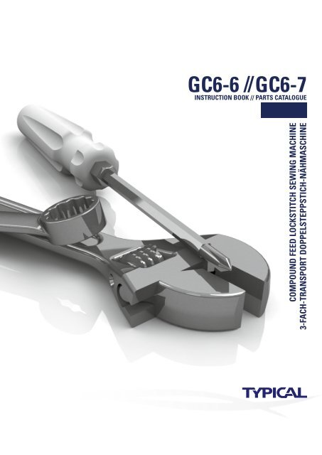
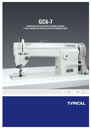
<strong>GC6</strong>-6 // -7Compound Feed Lockstitch Sewing Machine3-fach-Transport Doppelsteppstich-NähmaschineThis machine may only be operated by adequately trained operatorsonly after having completely read and understood the instruction manual.Parts are subject to changes in design without prior notice.Certificate of theinternational ISO9001Certificate of theISO14001Certificate of theinternational CECertificate forEcolabelling ProductCertificate for EnergyConservation ProductXI´an TYpical EUROPE GmbHHertelsbrunnenring 9D-67657 KaiserslauternTel.: +49 (0)631 316019-0Fax: +49 (0)631 316019-11E-mail: sales@typical-europe.comwww.typical-europe.com<strong>GC6</strong>-6 // <strong>GC6</strong>-7 – Manual – EN – 06-2011


