RS-NAGU.2f - automation-safety
RS-NAGU.2f - automation-safety
RS-NAGU.2f - automation-safety
- No tags were found...

You also want an ePaper? Increase the reach of your titles
YUMPU automatically turns print PDFs into web optimized ePapers that Google loves.
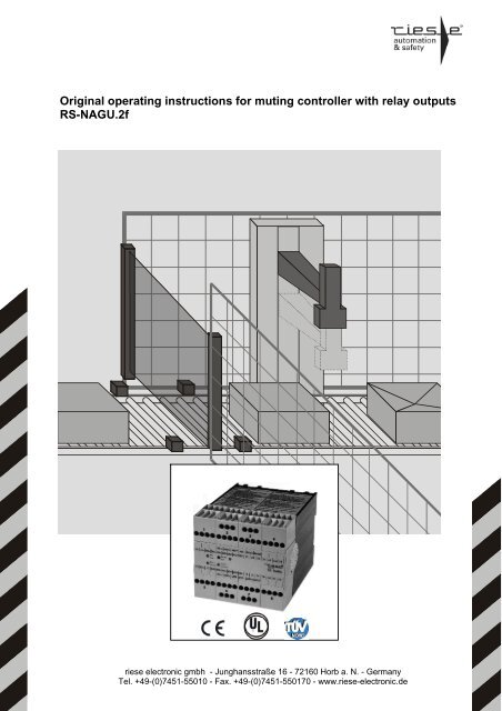
Original operating instructions for muting controller with relay outputs<strong>RS</strong>-<strong>NAGU.2f</strong>riese electronic gmbh - Junghansstraße 16 - 72160 Horb a. N. - GermanyTel. +49-(0)7451-55010 - Fax. +49-(0)7451-550170 - www.riese-electronic.de
IntroductionThese operating instructions should familiarize you with the muting controller <strong>RS</strong>-<strong>NAGU.2f</strong>. The following pages contain information about:• Structure and function• Assembly• Electrical installation• Maintenance and repair• Possible failures and actions to rectify failuresTarget audienceThese operating instructions are intended for the following persons:• Skilled personnel who plan or develop <strong>safety</strong> equipment for machines and plantsand are familiar with the <strong>safety</strong> instructions and <strong>safety</strong> regulations.• Skilled personnel who build in <strong>safety</strong> equipment into machines and plants andactivate them.Explenatin ofsignsThe operating instruction contains several symbols which are used to high-lightimportant information:!This symbol show text passages which should absolutely payed attention too. Nonobservanceleads to serious injuries or damage to property.⇒This symbol show text passages which contain important information.This sign is placed for activities.This sign shows a description how the condition has changed after an activity hasbeen carried out.This symbol marks the transmitter of a <strong>safety</strong> light barrier / -grid.This symbol marks the receiver of a <strong>safety</strong> light barrier / -grid.Explanation of termsBWS = ESPEMutingRestart inhibitList of contentsElectro sensitive protective equipment include light barriers,light curtains and light gridsTemporary bypassing of a ESPE in order to transport materialinto or out of the danger area.Prevention of automatic restart of the machine..Safety instructions page 3Structure and function page 4Muting components and function page 6Installation and implementing page 8Usage as a controller for <strong>safety</strong> light barriers page 13Maintenance and repair page 14Troubleshooting page 14Technical data page 16© Copyright. All rights reserved. Subject to changes in the interests of technical progress.<strong>RS</strong>-<strong>NAGU.2f</strong> - 270912 2/16
Safety instructionsIntended useThe muting controller <strong>RS</strong>-<strong>NAGU.2f</strong> is used in conjunction with <strong>safety</strong> light barriers or<strong>safety</strong> light grids to safeguard danger areas and hazard points. The integrated mutingfunction permits goods to be transported into or out of the danger area withoutimpairment to the <strong>safety</strong> function of the equipment.The <strong>RS</strong>-<strong>NAGU.2f</strong> may also be used as a controller for <strong>safety</strong> light barriers. Please note the wiring instructions for this operating mode on page 13.!The <strong>safety</strong> of persons and equipment cannot be guaranteed if the mutingcontroller is not used in accordance with its intended use.For your <strong>safety</strong>Observe the following points without fail:!• The device may only be build in and operated by specialized staff, who arefamiliar with this instruction and the current regulations for <strong>safety</strong> at workand accident prevention. Working on electrical equipment is only allowedfor specialized staff.• Any repairs have to be done by the manufacturer or a person which isauthorized by the manufacturer. It is prohibited to open the device orimplement unauthorized changes, otherwise any warranty expires.• Pay attention to valid regulations, particularly in reference to preventativemeasures and the installation of muting sensors, the muting lamp and theBWS.• The danger area must be observable by the assembling area of the startbutton.• It must be impossible to start the equipment from the danger area.• Avoid mechanical vibration and impacts during transport and operation.Impacts greater than 0.7 Nm or vibrations with a frequency > 33 Hz or anamplitude > 0.35 mm can lead to damage of the equipment.<strong>RS</strong>-<strong>NAGU.2f</strong> - 270912 3/16
Application and functionIntroductionThe muting controller <strong>RS</strong>-<strong>NAGU.2f</strong> is used in conjunction with <strong>safety</strong> light barriers or<strong>safety</strong> light grids to safeguard danger areas and danger points up to category 4 to EN13849-1. The integrated muting function to EN 61496 permits goods to be transportedinto or out of the danger area without impairment to the <strong>safety</strong> function.The device is suitable and tested for connection to <strong>safety</strong> light barriers and light gridsfrom a wide range of different manufacturers. A current list of tested light grids / lightbarriers and the relevant wiring instructions are provided in the "Applications"brochure. Should you not find the <strong>safety</strong> light barrier or <strong>safety</strong> light grid you wish touse in this list, please contact us by telephone.The diagram below provides an initial impression of connection possibilities. In thesection "Installation and commissioning", step-by-step instructions are provided onelectrical connection of the muting controller.BWS+24V GNDVCCGNDVCCGNDO1O2MS1+MS1PMS1NMS1-MS2+MS2PMS2NMS2-MS3+MS3PMS3NMS3-MS4+MS4PMS4NMS4-ERK+ERK131433342324A1+ESTEST+ESSESS+53AMLA1+6364A2BWS2PBWS1PA2-BWS1NBWSE-BWS2NA2-A1+ResetStartKey switchMuting lampMuting sensorsK2K1Bridge in case of no extensions contactors24 V DCK1GNDGND24 V DCK2Safety outputs with extension andfeedback circuitDevice typesType Description Order number<strong>RS</strong>-<strong>NAGU.2f</strong> Device with fixed terminal strips AR.9667.9020<strong>RS</strong>-<strong>NAGU.2f</strong> - 270912 4/16
OutputsThe muting controller has the following outputs:• Three <strong>safety</strong> relay outputs (13-14, 23-24, 33-34) as n.o. contacts.• One signal output (73-74) as a n.o. contact. The signal output connects as long asthe muting is active.• Two optocoupler outputs (OP-O1, OP-O2)OP24 V DCO1Optocoupler output O1 switches to 24V when the <strong>safety</strong> outputs are active. Optocoupleroutput O2 switches to 24V when the connected <strong>safety</strong> light barrier is not delivering asignal. This can be the case when the device is switched off or in the muting mode,provided there are moving objects located in the area of the <strong>safety</strong> light barrier.DisplayFive LED’s are used to indicate status.MS1+ MS1N MS1PMS1- BWS1N BWS1POPO1O2A1+A1+ ESS+ ERK+ ERK MS2+ MS2N MS2P MS2- 13 23 33 53 631Netz StörungPower 2 Fault 34Kanal 1Channel1 5Kanal 2Channel2AMLPE<strong>RS</strong>-NAGU.2..ESS EST+ EST BWSE+ BWSE- MS4+ MS4N MS4P MS4- 14 24 34 54 64 A2- A2-MS3+ MS3N MS3P MS3+ BWS2N BWS2P 73 741 Power ON2 Fault3 Restart inhibit on, waiting for start4 Operation – Channel 1 activated5 Operation – Channel 2 activated4+5 flashing Error codeFunctionAfter applying the supply voltage, the device performs a self test. LED’s 1,3,4 and 5light up and the device can be activated by pressing the start button.If the self-test has not been successfully executed, there is a fault or a connectionerror. For details, see the section "Troubleshooting" on page 15.If it is not possible to start the device by pressing the start button, at least one of themuting sensors is blocked or incorrectly connected. In the case of blocked mutingsensors, see the section "Muting components and function".<strong>RS</strong>-<strong>NAGU.2f</strong> - 270912 5/16
Muting components and functionMLESTESSMS4MS1MS2MS3MutingMuting lampDanger areaMS1, MS2, MS3, MS4 Muting sensors ML Muting lampEST Start button ESS Key-operated switchMuting is a temporary, automatic and reliable way of bypassing a presence-sensingsafeguarding device (ESPE), in order to transport material into or out of a dangerarea. For this purpose, two or four muting sensors (MS 1-4) are installed at theentrance/exit of the danger area in such a way that only the material activates thesensors. The muting controller then initiates the muting cycle for the period duringwhich the material is being transported through the protected field. It is not possible fora person to activate the muting sensors in the same way. A person approaching thedanger area will trigger a shut-down of the hazardous movement.During material transport through the protected field, the muting controller switchesthe muting lamp (ML) on. The muting controller monitors the filament of the muting lampeven when the muting function has not yet been initiated. If the filament is defective, or ifno lamp is connected, the muting controller indicates a failure and the <strong>safety</strong> outputs areswitched off.Key-operated switchIn accordance with EN 61496-1, the following conditions must be adhered to bythe muting lamp. The luminous surface must be at least 1cm² and have abrightness of at least 200cd/m².On start-up of the ESPE using the start key (EST), the muting controller checkswhether all the muting sensors are inactive. If this is not the case, for example after afault in which the material is already located in the area monitored by the mutingsensors, the output signals of the muting controller are not switched, in other wordsthe plant comes to a standstill. Using the key-operated switch, the muting cycle can bestarted and the material can continue to be transported. The muting cycle remainsactive as long as the key-operated switch is actuated, but for a maximum of tenminutes.If all muting sensors are subsequently free, the enable circuits and the muting lampswitch off. Release the key-operated switch and press the start key.If the key-operated switch is released prematurely, the enable circuits switch off andthe muting lamp remains alight. Press the key-operated switch again.<strong>RS</strong>-<strong>NAGU.2f</strong> - 270912 6/16
Muting sensorsMechanical, inductive, capacitive and opto-electronic sensors are suitable as mutingsensors, whereby both sensors with solid-state outputs and also with relay outputscan be used. If retroreflective light barriers are used as muting sensors, they arearranged across corners. The cross-over point of the light beams must be locatedbehind the <strong>safety</strong> light barriers in the danger area.MS1MS4MS1MS2MS3MS21. The muting sensors must have a rated voltage of 24 V DC at the output.2. Only light barriers with a dark switching output can be connected to themuting controller as muting sensors.Sequence of amuting cycleIf the muting sensors MS1 and MS2 are activated within a 3-second period, the mutingcycle is initiated. The muting lamp is switched on and interruption of the <strong>safety</strong> lightbarrier does not cause the device to switch off. If three of the four muting sensors areinactive, the muting cycle is terminated after a delay period of 0.25 seconds.MLMLMLMLMLMS1MS4MS1MS4MS1MS4MS1MS4MS1MS4MS2MS3MS2MS3MS2MS3MS2MS3MS2 MS3aMS1it1 t2 t3 t5aMS2iaMS3iaMS4iMLaiaMutingi0,25 sa: activei: inactive t
Installation and implementing!Dust and moisture can lead to malfunctions. Install the device in a dust anddamp-proof housing, for example in a switch cabinet or a IP54 housing.MechanicalinstallationMount the muting controller on a universal mounting rail.!Short circuits, broken cables, power failure or voltage fluctuations in the networkcan impair and/or cancel the <strong>safety</strong> function and result in serious accidents.Pay attention to the following points:• The <strong>safety</strong> solid-state output lines and the lines of the two muting sensorgroups must be lay in separate non-metallic-sheathed cables.• When using two light barriers as muting sensors, the voltage supply for thetransmitters must be lay separately and wired separately to the terminals.• No circuits may be used which generate a muting signal in case of a cablebreakage or power failure.• The power supply to the device and all connections must be reliably isolatedfrom the light / threephase mains, either by using an isolating transformer inaccordance with IEC 60742 or an equivalent disconnecting device.ElectricalconnectionWiring of the muting controller is subdivided into two areas:1. General wiring2. Specific wiring according to the ESPE (BWS) type usedAll steps for general wiring are described in the following. A precise description of thespecific wiring is provided in the separate brochure "Applications".<strong>RS</strong>-<strong>NAGU.2f</strong> - 270912 8/16
Terminals1234MS1+ MS1N MS1PMS1- BWS1N BWS1POPO1O2A1+A1+ ESS+ ERK+ ERK MS2+ MS2N MS2P MS2- 13 23 33 53 63 AML PENetzPowerKanal 1Channel1StörungFaultKanal 2Channel2<strong>RS</strong>-NAGU.2..ESS EST+ EST BWSE+ BWSE- MS4+ MS4N MS4P MS4- 1424345464A2-A2-MS3+ MS3N MS3PMs3-BWS2N BWS2P73745678PinsMeaningA1+ , A2- Connection of supply voltageEST+, ESTStart buttonESS+, ESSKey-operated switchESS+, 53Muting lampAML, 53Bridge when NAGUis used as a controller for <strong>safety</strong> light barriersERK+, ERKFeedback circuitMSx+Positive voltage for muting sensor xMSx-Negative voltage for muting sensor xMSxPInput of muting sensor x -PNPMSxNInput of muting sensor x -NPNBWSE+Positive voltage for BWS signalsBWSE-Negative voltage for BWS signalsBWSxPInput of BWS channel x - PNPBWSxNInput of BWS channel x - NPN13-14, 23-24, 33-34 Relay <strong>safety</strong> outputs63-64 Relay output for activating the BWS54 Negative internal supply voltage (internallyconnected to EST-, ESS-, ERK-, BWSE-, MSx-)73-74 Signal output connects as long as mutingis activeOP, O1, O2Optocoupler outputs<strong>RS</strong>-<strong>NAGU.2f</strong> - 270912 9/16
Wiring+24V• Supply voltage• Key-operatedswitch• Muting lamp• Start buttonKeyswitchResetA1+A1+ESS+ERK+MutinglampMS1+ MS1N MS1P MS1- BWS1N BWS1P OP O1 O2ERK MS2+ MS2N MS2P MS2- 13 23 33 53 63 AML PE<strong>RS</strong>-NAGU.2..ESSEST+ESTMS4-BWSE+ BWSE-MS4+MS4NMS4P1424345464A2-A2-MS3+MS3NMS3PMS3-BWS2N BWS2P 73 74StartGNDConnect the key-operated switch to terminals ESS+ and ESS.Connect the muting lamp to terminals ESS+ and 53.Connect the start button to terminals EST+ and EST.Only connect the operating voltage to terminals A1+ and A2- when theremaining wiring has been completely connected.Wiringmuting sensorsMuting sensors are wired depending on the operating mode, type and number ofsensors. Either 2 or 4 muting sensors must be connected to the muting controller.When using two muting sensors, these must be connected to terminals MS1... andMS2... . Connect the muting sensors in accordance with the instructions below.Muting sensorwith PNP outputMuting sensor with NPN outputMuting sensor with relay outputVCCGNDPNPVCCGNDNPNMS1+ MS1N MS1P MS1- MS1+ MS1N MS1P MS1- MS1+ MS1N MS1P MS1-NAGU.2.. NAGU.2.. NAGU.2..MSxP and MSxN must always be connected from the connected muting sensor inputs.If the muting sensor only makes one signal available, the remaining unassigned terminalat the <strong>RS</strong>-NAGU... must be connected as follows.Insert a bridge between MSx- and MSxN, when MsxN is unassigned at the <strong>RS</strong>-NAGU...Insert a bridge between MSx+ and MSxP, when MsxP is unassigned at the <strong>RS</strong>-NAGU...1. If 4 muting sensors are connected, sensors with the same polarity must beused at the terminals MS1.. and MS4.. / at MS2.. and MS3.. .2. The terminals for MS1../MS4.. and MS2../MS3.. must be laid in separateconted cables.<strong>RS</strong>-<strong>NAGU.2f</strong> - 270912 10/16
WiringBWSThe precise wiring of the ESPE (BWS) depends on the type and manufacturer. Ingeneral, however, the following wiring rules apply:1. Connect the outputs at the ESPE (BWS)Connect the outputs of the BWS receiver directly to the inputs of the mutingcontroller (BWS1P, BWS1N, BWS2P, BWS2N) .Example 1: <strong>safety</strong> light barrier receiver with 2 PNP solid state outputsExample 2: <strong>safety</strong> light barrier receiver with 2 relay outputsVCC GND PNPPNPBWS24 V DC 24 V DCGNDGNDVCCGNDBWSBWSE+ BWSE-BWS1PBWS1NBWS2PBWS2NBWSE+ BWSE-BWS1PBWS1NBWS2PBWS2NNAGU.2..NAGU.2..In the case of <strong>safety</strong> light barriers / light grids with solid-state outputs, the lightswitching outputs must be used.2. Connect the operating voltageConnect the ESPE (BWS) receiver directly to the external power supply.Connect the ESPE (BWS) transmitter to the muting controller in accordancewith the instructions below. The BWS is activated via terminal 63 and 64.Direct connectionConnection with additional relayConnection with additonal relay and test input24 V DCVCCGNDBWS VCC GND BWS VCC GND Test BWS24 V DC24 V DCGNDGND646324 V DCGNDGND64 63 64 63NAGU.2.. NAGU.2.. NAGU.2..Direct power supply to the transmitter is only admissible if:• The current consumption is smaller than 2 A and• The peak current is smaller than 5 A and• The supply voltage does not fall below 21.6V at this moment in time.If these values are exceeded, a supplementary relay (e.g. type <strong>RS</strong>-IR2 from rieseelectronic) must be interconnected.!The use of external relays without spark suppressors can result in damage tothe muting controller. For this reason, always connect external relays with aspark quenching diodes, e.g. type 1N4007.<strong>RS</strong>-<strong>NAGU.2f</strong> - 270912 11/16
Wiring<strong>safety</strong>outputsThe <strong>safety</strong> outputs must be electrically integrated in accordance with the category asspecified by EN 13849-1 and DIN EN 60204-1.The terminals 13-14, 23-24 and 33-34 are <strong>safety</strong> relay outputs. If the muting controllerhas started and the light beam of the BWS is unobstructed, the outputs will also beconnected. In the deactivated status, the outputs are open.Expansion modules <strong>RS</strong>-NAGX5 are provided in order to expand the <strong>safety</strong> outputs.For wiring details, see page 13.To expand the <strong>safety</strong> outputs, relay with positive guided contacts are alsoadmissible.Depending on the category, the following wiring arrangements must be executed.Safety category B and 1Safety category 4 with feedback circuitGND24 V DCERK+ERK1413K1 extGNDNAGU.2..24 V DCERK+ERK1413Safety category 2 with feedback circuitNAGU.2..3334GND24 V DCK2 extGND24 V DCERK+ERK1413NAGU.2..!The use of external relays without a recovery diodes can result in damage to themuting controller. For this reason, always connect external relays with arecovery diode, e.g. type 1N4007.<strong>RS</strong>-<strong>NAGU.2f</strong> - 270912 12/16
Wiringfeedback circuitUsing the feedback circuit, it is possible to monitor the statuses of these modules viathe n.c. contact of an external contactor or of the expansion module, for example, the<strong>RS</strong>-NAGX5 from riese electronic.Connect the expansion module in accordance with the following circuit diagram.ERK+ERK 34A1 Y1 Y213 23 33 43NAGU.1NAGX5NAGU.12NAGU.1b1414 24 34 4453 54 A2Usage as a controller for <strong>safety</strong> light barriersFunctionThe muting controller <strong>NAGU.2f</strong> can also be used as a controller for <strong>safety</strong> lightbarriers. In this case, the inputs for the muting sensors remain unconnected. The keyoperatedswitch and muting lamp are not connected. A bridge must be insertedbetween the terminals 53 and AML. After the start, the outputs 13-14, 23-24 and 33-34are connected. Other functions of the device are not affected.Circuit diagramBWS+24V GNDVCCGNDVCCGNDO1O2MS1+MS1PMS1NMS1-MS2+MS2PMS2NMS2-MS3+MS3PMS3NMS3-MS4+MS4PMS4NMS4-ERK+ERK131433342324A1+ESTEST+ESSESS+53AMLA1+6364A2BWS1NBWSE-BWS2NBWS2PBWS1PA2-A2-A1+ResetStartSafety outputs<strong>RS</strong>-<strong>NAGU.2f</strong> - 270912 13/16
Maintenance and repairThe muting controller works maintenance free.In the device <strong>RS</strong>-<strong>NAGU.2f</strong>, the terminal blocks are not detachable.NetzPowerKanal 1Channel1StörungFaultKanal 2Channel2TroubleshootingThe muting controller is equipped with comprehensive troubleshooting functions. If anerror is discovered, one or both LED’s of channel 1 and channel 2 begin to flash.Thereby it’s possible that under certain circumstances both LED’s indicate differenterrors. The error code can be read off by the flashing LED’s.Example:The channel 1 LED flashes 9 times (code 9) channel 2 LED flashes once (code 1)⇒ channel 1 LED indicates the error "Muting lamp interrupted" and⇒ channel 2 LED indicates the error "Inequality of the two channels".At the same time, the fault LED lights.Tip: If both LED’s are alight, the flashing code can be more easily read by coveringover the other LED.On the next page, you will find a breakdown of all flashing codes with the relevantexplanations, their possible causes and actions which can be initiated to remove thefailure.1. In case of an error, also check the supply voltage. At terminals A1+ and A2-24 V DC must be available also after connecting all consumers to thissupply voltage.2. When switching devices or light barriers, the voltage must not drop below21.6 V DC.<strong>RS</strong>-<strong>NAGU.2f</strong> - 270912 14/16
Fault diagnosticsBC Fault Possible cause What to do1 Differences between the channels - Only one Channel detect an Error Look at the error code of the otherchannel2 One of the channels does not work - One channel defect Reset3 Feedback circuit open - Normally closed contacts ofexpansion relays are not wired Check wiring- Bridge not wired4 Start button constantly activated - Start button defect- Start switch is used instead ofstart button5 Key switch is activated during starting - Key switch activated- Key switch defect Reset6 BWS Empfänger aktiv bei Start - Wiring error of the light barrier7 Internal fault of the <strong>safety</strong> output - Wiring error of <strong>safety</strong> outputs- Disturbances on the access line- Output defect8 Internal fault of light barrier senderoutput- Wiring error of <strong>safety</strong> light barrier- Disturbances on the access line- Output defect9 Muting lamp disconnected - Muting lamp defect- Muting lamp is missing- No bridge by application as controllerfor light barriers10 Two starts with key switch - After the clearance of the lightbarrier the key switch was activateda second time11 Light barrier disconnected during startor time out on light barrier receiver12 Simultaneousness of muting sensorsexceeded (3s)- Wiring error of <strong>safety</strong> light barrier- Optical Path is broken- Timeout reached- Wrong position of the mutingsensors- Only one muting sensor wasactivated13 Internal fault of muting lamp control - Wiring error of the muting lamp- Muting lamp defect- terminal 53 is connected to GND- Output defect Check expansion relays Check start button on short circuit Check start button (must be a button) Check key switchCheck wiring; light barrier must activatedwith output 63Check wiring of <strong>safety</strong> outputs, payattention to wiring advice!Check wiring of output 63, BWSE+,pay attention to wiring advice!Check muting lamp and change ifneccessary Reset Check wiring Check optical pathCheck technical data of the light barrier(start time, power consumption)Reduce current consumption withadditional relayCheck position of muting sensors, thematerial must activate both sensorswithin 3s all muting sensors wired ?Check wiring at terminal 53 and ESS+Check muting lamp14 Muting time with key switch exceeded - Manual muting timeout (10 min)reached Reset15 Internal memory fault - Disturbances on the access line- Internal error Reset; if BC comes again: check systemon disturbances<strong>RS</strong>-<strong>NAGU.2f</strong> - 270912 15/16
Technical dataElectrical dataSupply voltage Uv24 V DCVoltage range0,90 ...1,1 UvRemaining ripple ≤ 5%Power consumption without peripheral devices appr. 10 WConductor connection1 x 4,0 mm 2 massive wire (Cu)2 x 1,5 mm 2 strand with hull (Cu)Use 60/75°C copper wire only!Contact allocation3 n.o. contactsSwitching voltage24 V DCDelay off (light curtain)< 20 msInput currentappr. 15 mA for each inputSimultaneousness of muting sensors3 sMuting timemax. 10 minutes by key switch, infinite during normal operationStartup waiting time for <strong>safety</strong> light curtain receiver max. 6 safter ‚Start‘Switching current output 13-14, 23-24, 33-34 1,5 A permanent currentOutput 63-64 (light barrier)Relay 1,5 A / 24 V DCOutput 74-74 (muting signal)Relay 1,2 A / 24 V DCOutput OP-O1, OP-O2Optocoupler 20 mA /24 V DCPower supply muting sensorsTogether max. 0,5 A (24 V DC)Output 53 (muting lamp)24 V DC, max. 1 AMechanical dataHousing material Self extinguishing according to UL 94 V-0Dimensions (WxHxD)90x84x121 mmMountingSnap mounting on universal mounting rail NS35 according toDIN EN 50022Max. tighening torque0,4 Nm (Tighten to 1 N.m. Overtorquing may cause enclosure breakage.)Weight with terminalsStorageIn dry areasEnvironmental dataEnvironment temperature-25°C ... +55°CHumidityOperation 75% (No dewing), Storage 85% (No dewing)Creeping distance and clearingDIN VDE 0110 part 1 at polution grade 2, basic isolation: over voltagecategory 3; safe breaking: over voltage category 2Terminal type IP 20Housing type IP 40Shock resistance< 0,7 NmVibration resistanceFrequency < 33 Hz, Amplitude < 0,35 mmCertificationsTested in accordance with EN ISO 13849-1:2006Achieved level/categoryPerformance Level e, Kat.4MTTFd [years]>100 “high”DC99% “high”CCFachievedbeantragt848090Mounting railDIN EN 50022113118<strong>RS</strong>-<strong>NAGU.2f</strong> – 270912 16/16
Ihr Kontakt zu riese electronic / your contact to riese electronic:Weitere Länder- / Gebiets – Vertretungen finden Sie auch im Internet:all our representations can be found on our homepage:www.<strong>automation</strong>-<strong>safety</strong>.de/deutsch/index.htmwww.<strong>automation</strong>-<strong>safety</strong>.com/englisch/index.htmDeutschlandStammhaus: / Head officeJunghansstr. 16D-72160 Horb am NeckarPhone: +49 74 51 / 55 01 0Fax: +49 74 51 / 55 01 70info@riese-electronic.dewww.<strong>automation</strong>-<strong>safety</strong>.dewww.<strong>automation</strong>-<strong>safety</strong>.comExemplarisch ein Vertreter auf jedem KontinentExemplary one representation on each continentUSANorstat Inc.Rockaway, NJ07866Phone: +1 97 35 86 25 00Fax: +1 97 35 86 15 90Info@norstat.comwww.norstat.comStammhaus:Head office:Serviceadresse für ganz Europa /servic adress for europeNiederlassung Ost Langenwolschendorf /Langenwolschendorf branchDr.-Riese-Str. 1D-07937 LangenwolschendorfPhone: +49 3 66 28 / 72 5 0Fax: +49 3 66 28 / 72 5 17Email: info-lawo@<strong>automation</strong>-sicherheit.deTaiwanDaybreakTaipei TaiwanPhone: +88 62 88 66 12 31Fax: +88 62 88 66 12 39Day111@ms23.hinet.netSouth AfricaCurmec CCP.O.Box 1818Bedfordview 2008/GautengZA-Germiston 1401Phone: +27 11 87 30 53 6Fax: +27 11 87 39 74 3info@curmec.co.zawww.curmec.co.zaBitte fordern Sie zusätzlich Unterlagen an: /Please ask for our additional information on:•Zeitrelais / time-delay relays•Messrelais / measuring relays•Sicherheitsrelais / <strong>safety</strong> relays•Kundenspezifische Entwicklung und Fertigung elektronischer Baugruppen/custom-made designs and the fabrication of electronic subassemblies•Leitfaden für eine partnerschaftliche Elektronikfertigung / (only in German)