Indian Welding Journal - The Indian Institute of Welding
Indian Welding Journal - The Indian Institute of Welding
Indian Welding Journal - The Indian Institute of Welding
- No tags were found...

You also want an ePaper? Increase the reach of your titles
YUMPU automatically turns print PDFs into web optimized ePapers that Google loves.
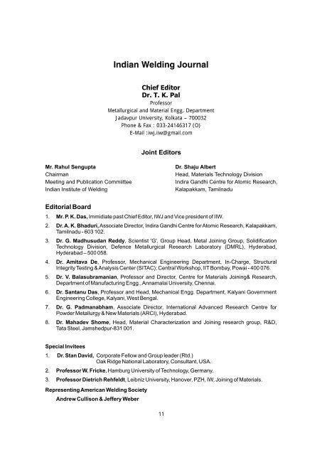
<strong>Indian</strong> <strong>Welding</strong> <strong>Journal</strong>Chief EditorDr. T. K. PalPr<strong>of</strong>essorMetallurgical and Material Engg. DepartmentJadavpur University, Kolkata – 700032Phone & Fax : 033-24146317 (O)E-Mail :iwj.iiw@gmail.comJoint EditorsMr. Rahul SenguptaChairmanMeeting and Publication Commiittee<strong>Indian</strong> <strong>Institute</strong> <strong>of</strong> <strong>Welding</strong>Dr. Shaju AlbertHead, Materials Technology DivisionIndira Gandhi Centre for Atomic Research,Kalapakkam, TamilnaduEditorial Board1. Mr. P. K. Das, Immidiate past Chief Editor, IWJ and Vice president <strong>of</strong> IIW.2. Dr. A. K. Bhaduri, Associate Director, Indira Gandhi Centre for Atomic Research, Kalapakkam,Tamilnadu - 603 102.3. Dr. G. Madhusudan Reddy, Scientist 'G', Group Head, Metal Joining Group, SolidificationTechnology Division, Defence Metallurgical Research Laboratory (DMRL), Hyderabad,Hyderabad – 500 058.4. Dr. Amitava De, Pr<strong>of</strong>essor, Mechanical Engineering Department, In-Charge, StructuralIntegrity Testing & Analysis Center (SITAC); Central Workshop, IIT Bombay, Powai - 400 076.5. Dr. V. Balasubramanian, Pr<strong>of</strong>essor and Director, Centre for Materials Joining& Research,Department <strong>of</strong> Manufacturing Engg., Annamalai University, Chennai.6. Dr. Santanu Das, Pr<strong>of</strong>essor and Head, Mechanical Engg. Department, Kalyani GovernmentEngineering College, Kalyani, West Bengal.7. Dr. G. Padmanabham, Associate Director, International Advanced Research Centre forPowder Metallurgy & New Materials (ARCI), Hyderabad.8. Dr. Mahadev Shome, Head, Material Characterization and Joining research group, R&D,Tata Steel, Jamshedpur-831 001.Special Invitees1. Dr. Stan David, Corporate Fellow and Group leader (Rtd.)Oak Ridge National Laboratory, Consultant, USA.2. Pr<strong>of</strong>essor W. Fricke, Hamburg University <strong>of</strong> Technology, Germany.3. Pr<strong>of</strong>essor Dietrich Rehfeldt, Leibniz University, Hanover, PZH, IW, Joining <strong>of</strong> Materials.Representing American <strong>Welding</strong> SocietyAndrew Cullison & Jeffery Weber11
EDITORIALEDITORIALFirst <strong>of</strong> all I would like to thank council members <strong>of</strong> <strong>The</strong> <strong>Indian</strong> <strong>Institute</strong> <strong>of</strong> <strong>Welding</strong> for giving me the opportunity to actas Chief Editor <strong>of</strong> <strong>Indian</strong> <strong>Welding</strong> <strong>Journal</strong> from January issue.You will agree that the economic growth <strong>of</strong> India over the period has changed her position and has involved changes inher industrial structure. <strong>The</strong>se changes greatly affect the status <strong>of</strong> welding engineering and technology in the presentindustrial society. <strong>The</strong> <strong>Indian</strong> <strong>Institute</strong> <strong>of</strong> <strong>Welding</strong> has also decided to restructure itself to adopt to these newenvironments.We have come round an eventful year for the <strong>Indian</strong> <strong>Institute</strong> <strong>of</strong> <strong>Welding</strong> as well as <strong>Indian</strong> <strong>Welding</strong> <strong>Journal</strong>. Ourthinstitute hosted the prestigious event “64 Annual Assembly & International Conference <strong>of</strong> theInternational <strong>Institute</strong> <strong>of</strong> welding, Chennai, India, July 17-22, 2011”, being held for the first time in ourcountry and our annual assembly "NWS 2011" during December 16-18, 2011 at Bhilai.IWJ provides a forum for the multidisciplinary subjects within joining <strong>of</strong> materials and helped to encouragedevelopments and information exchange <strong>of</strong> important work within the field. In this issue, there are three awardedtechnical papers which would be <strong>of</strong> interest to both welding and material engineers.We have the pleasure to put on records our compliments to Dr. R. S. Parmar, who made valuable contribution towelding technology and the institute, for being chosen to receive the “Life time achievement award” andMr. P. K. Das, immediate past Chief Editor and Vice President <strong>of</strong> our institute, for being promoted the journal a new lookidea and making them available for advertisement and sponsorship.IWJ is proud to welcome the new board members, who are recognized for their significant contribution towards thegrowth <strong>of</strong> welding technology. It is my hope that the new editorial board will play an important role and with thesupport from related organizations, contribute to the prosperity and welfare <strong>of</strong> human being and <strong>of</strong> global society.<strong>The</strong> January issue <strong>of</strong> the journal is coming out during mid February. Late receipt <strong>of</strong> materials for publication has causedthis delay which we sincerely regret. <strong>The</strong> cooperation and ideas from all members shall continue to make the journalmore valuable in future.Before we end, we from IWJ wish all our readers, home and abroad, a very Happy, Prosperous and eventful 2012.T. K. PalChief-EditorEmail: iwj.iiw@gmail.com13
IIW NEWSIIW NEWSNATIONAL WELDING SEMINAR – 2011HELD AT BHILAIREPORT FROM IIW BHILAI BRANCH<strong>The</strong> National <strong>Welding</strong> Seminar – 2011 (NWS-2011) wasorganized by the Bhilai Branch <strong>of</strong> the <strong>Indian</strong> <strong>Institute</strong> <strong>of</strong>welding in association with Bhilai Steel Plant (SAIL)during December 15th – 17th, 2011 and this was thethird occasion the branch hosted this mega event after agap <strong>of</strong> five years. <strong>The</strong> theme <strong>of</strong> the seminar was“<strong>Welding</strong> Science & Technology in InfrastructureIndustries”. While the Inaugural session held at KalaMandir Auditorium, the technical sessions andconcluding session were held at Bhilai Niwas, both withinthe Bhilai Steel Plant township. Around 225 delegateswere drawn from a variety <strong>of</strong> fields like EducationalInstitutions, R & D, Industrial Consumables,Manufacturer etc. Altogether 40 papers were acceptedand 36 papers were presented during the seminar on awide range <strong>of</strong> topics.<strong>The</strong> Chief Guest Shri Pankaj Goutam, Chief ExecutiveOfficer <strong>of</strong> Bhilai Steel Plant and Chief Patron <strong>of</strong> BhilaiBranch <strong>of</strong> IIW, underlined the rising importance <strong>of</strong>welding in the infrastructure Industry and stressed theneed for constant updation <strong>of</strong> knowledge related to allaspects <strong>of</strong> welding. In the same vein Shri R. Ravi,President (IIW-INDIA) while enumerating the role <strong>of</strong>IIW in keeping the industry informed and guided in thelatest development taking place in the field.Other speakers including President IIW – Bhilai BranchShri P.K. Singh, ED (Works) BSP and Secretary General <strong>of</strong>IIW-INDIA Shri Parimal Biswas also stressed theimportance <strong>of</strong> such events for better applicability <strong>of</strong>welding as a Science & Technology.At the outset, Shri Debasish Thakur, Chairman (IIW-Bhilai Branch) and GM (Utility) BSP, welcomed thedignitaries, distinguished guests & delegates and briefedthe gathering about the Seminar and the action rolebeing played by the Bhilai Branch in spreading theobjective <strong>of</strong> IIW-INDIA.To commemorate the event a souvenir & CD, containingall the selected Technical Papers <strong>of</strong> NWS-2011, werereleased by the dignitaries.During Inaugural Session, various welding Awards,institutionalized by IIW-India, were ceremoniously givenaway for the papers presented during the last weldingseminar by the IIW-India president Shri R. Ravi & Chiefguest Shri Pankaj Goutam that also includes the bestwelding Engineer and best welders awards. <strong>The</strong>prestigious Life Time Achievement Award for year 2010-11 was given away to Dr. R. S. Paramar, Ex. Pr<strong>of</strong>. <strong>of</strong> IIT,Delhi.<strong>The</strong> two prominent memorial lectures viz Keith HartleyMemorial lecture & Dr. Placid Rodriguez Memorial lecturewere delivered by Dr. T. K. Pal, Pr<strong>of</strong>. <strong>of</strong> JadavpurUniversity & Dr. G. D. Janaki Ram, Pr<strong>of</strong>. <strong>of</strong> IIT, Madras ontopics 'Development <strong>of</strong> welding technology forauto-motive industries' & 'Emerging concepts inwelding research, respectively.Coming to Technical Sessions about 36 papers werepresented in two parallel run sessions. <strong>The</strong> sessionswere chaired by S/Shri N. K. Sarkar, V. S. Galgali, H. V.Sharma, C. K. Datta, P. K. Das, Dr. G. L. Datta, A. B.Purang, Dr. Madhusudan Reddy, H. K. Sethi & S. N. Singhall prominent persons in their chosen field <strong>of</strong>pr<strong>of</strong>essions.<strong>The</strong> papers covered the wide spectrum right fromResearch, New application, New developments,Economy & Health concern related to various aspect <strong>of</strong>welding.<strong>The</strong> speakers were all experts in their particular areasand did a splendid job in compiling their thought &research into their papers.Each paper was judged by 3 persons including thesession chairman and 2 delegates from audience. <strong>The</strong>seevaluation sheets have been handed over to Dr. ShajuAlbert, Chairman, Technical Committee (IIW-INDIA) fordeclaring the results.15
INDIAN WELDING JOURNAL Volume 45 No.1 January 2012<strong>The</strong> sumptuous lunches & dinners assisted by culturalprogrammes at night have only helped in assimilatingthese technical contents easily.Valedictory function was presided over by Dr. R. S.Parmar and concluding remarks was summed up by ShriParimal Biswas on behalf <strong>of</strong> the council.<strong>The</strong> proceedings <strong>of</strong> the entire activity were conducted byShri G. M. Arun Kumar, DGM (MARS); Mrs. ManjuHaridas, AGM (ERS); Shri V. K. Ogale, Sr. Mgr. (RMP-1)and Shri Umesh Malayath, Jr. Mgr. (CAS) while the vote<strong>of</strong> thanks was proposed by Shri Ajay Bedi, HonySecretary (IIW-Bhilai Branch).During the seminar, the 280th Council Meeting andAnnual Members Assembly were also held.<strong>The</strong> work <strong>of</strong> various committees, formed to make theevent a grand success, was highly acknowledged thatalso includes S/Shri S. K. Bansal, H. K. Sahu, R. K.Bisare, M. R. K. Sariff and D. Anand.REPORT OF THE BWE & BW COMPETITIONS,2011<strong>The</strong> National Level Competitions for the Best Weldersand Best <strong>Welding</strong> Engineer <strong>of</strong> the year, 2011-12 was heldat the <strong>Welding</strong> Reclamation Shop <strong>of</strong> the Bhilai SteelPlant, Bhilai on 13th December, 2011 and was conductedby Mr. N. K. Sarkar.Out <strong>of</strong> 11 branches, only 7 branches viz. Baroda, Bhilai,Chennai, Jamshedpur, Kolkata, Mumbai andVisakhapatnam participated in this year's competition,there were only five candidates in each category.IIW Mumbai Branch assisted by Mr. S. C. Mitra and Mr. T.K. Mitra both from Kolkata branch and Mr. S. C. Tutejafrom Bhilai.Mr. Biswajeet Paul <strong>of</strong> L&T Ltd., Mumbai was declared asthe Best <strong>Welding</strong> Engineer. He was given an AWARD <strong>of</strong>Rs. 7,000/- in cash and a certificate. He was registered asa free delegate for the NWS.Mr. Roque Fernandes <strong>of</strong> Don Bosco Maritime Academy,Mumbai was declared as the Best Welder in theStructural (Plate) <strong>Welding</strong> category and Mr. VinodKumar, R. Parmar <strong>of</strong> L&T, Baroda was declared as theBest Welder in the Pipe <strong>Welding</strong> category. Each <strong>of</strong> themwas given an Award <strong>of</strong> Rs.5000/- in cash and acertificate.All the Awards sponsored by ELCA Laboratories, Thane,Maharashtra were given to the winners during theInauguration ceremony at the National <strong>Welding</strong> Seminarheld at Bhilai on 15th December, 2011.IIW MES AB:A total number <strong>of</strong> 372 candidates assessed under thisscheme at various ITI in Gujarat under the activeleadership <strong>of</strong> Mr. R. R. Vishawakarma, Gujarat StateCoordinator & Authorised AssessorBRANCH ACTIVITY REPORTREPORT FROM BANGALORE BRANCH1. Program on “Advances in <strong>Welding</strong> & Testing”jointly conducted on 17th Nov 2011 by <strong>Indian</strong>Society for Non-Destructive Testing [ISNT], Societyfor <strong>Indian</strong> Aerospace SIATI Blr, where-in PadmashriDr. C. G. Krishnadas Nair was facilitated; and theBranch Chairman, Mr. N. Ramesh Rao delivered theKey-Note Address.2. Program on “Copper <strong>Welding</strong>, Brazing &Soldering” was conducted on 25th Nov 2011jointly with <strong>Indian</strong> Copper Development Centre,where-in the Branch Chairman Mr. N. Ramesh Raopresented a paper on “Considerations in implementingCopper <strong>Welding</strong> Procedures” .3. <strong>The</strong> Branch Committee members visited Mysore &Dharwad Regional Centres for Skill Development forpromoting <strong>Welding</strong> Training Programs; this wasarranged by the Branch Hony Secry Mr SV Dilipan.4. <strong>The</strong> Branch Committee members visited AdvancedSimulator Training Facility for Skill Development forpromoting <strong>Welding</strong> Training Programs; this wasarranged by the Branch Hony. Secy. Mr. S. V. Dilipan16
IIW NEWSREPORT FROM BARODA BRANCHI. One-day SeminarOrganised Seminar on "<strong>Welding</strong> in PressureVessels Industries" - as 13th Foundation DayCelebration, held on 15th October 2011 at HotelSurya Palace.<strong>The</strong> Seminar was inaugurated by lighting the lampby Chief Guest Mr. R. K. Batra & other dignitariespresent on dias. On this occasion, the Souvenircovering technical papers, advertises & IIWinformations etc., was released by Chief Guest.<strong>The</strong> Chief Guest Mr. R. K. Batra, Exe. Director(Project & Construction, Engineers India Ltd ) in hisinaugural speech emphasized on the need <strong>of</strong>welding knowledge sharing to various pr<strong>of</strong>essionalsin the construction industries and training to thewelding inspectors as well as welders to improveupon the skill and performance to achieve the bestquality standards.<strong>The</strong> Convenor <strong>of</strong> the seminar was Mr. D. C. Mehtaand the technical session was chaired by Mr. R. R.Chhari. <strong>The</strong> Seminar received overwhelmingresponse from various advertisers & sponsors.<strong>The</strong> Seminar was Sponsored by M/s Vijay Tanks andVessels (Baroda) and by M/s Satkul Enterprises Ltd,(Ahmedabad).II. Technical Lectures :Following Technical Lectures were organized :1. “Comparison between ASME and ENrequirements for Welders and <strong>Welding</strong>Procedure Qualification” by Mr. MahendraShiroya (QMOS-LeveIII Inspector) and Mr. SunitKumar (PED Inspector) from M/S. Bureau Veritas(India) Pvt. Ltd., Baroda, on 14th July 2011 at HotelRevival Lords INN. near Sayaji Garden, Vadodara.67 Participants attended.2. “<strong>Welding</strong> <strong>of</strong> Nickel and High Alloy Steels”Presented by Dr. K. Manfred Rostek, TechnicalDirector, Selectarc Industries, France, on 14thDecember 2011 at Hotel Surya Palace. 85Participants attended.3. “Seam less flux/metal cored wires suitablefor pipe line, <strong>of</strong>fshore & shipbuildingapplications” Presented by Mr. Martin Schnirch,Sales Director & Mr. Andreas Holzner, Head <strong>of</strong>Quality and Application Management DrahtzugStein wire & welding (German Company).III. Workshop Training :Following workshop training programmes wereconducted1. WPS/PQR workshop from 17th to 18th December2011 at Hotel Sayaji, Vadodara. Total 26participants attended the workshop. <strong>The</strong> workshopconducted was to educate the welding engineerson the different aspects <strong>of</strong> preparing WPS/PQR asper ASME Section IX Code requirements. At the end<strong>of</strong> the workshop participants were given casestudies to prepare the WPS on their own andpresent it to all.<strong>The</strong> Convenor <strong>of</strong> the programme was Mr. KashyapBhatt, supported by Mr. Vijay Patel, Mr. R. R. Chhariand Mr. B. S. Kandpal as faculties and evaluationteam members.2. NDT Level II (Visual Testing) course from 23rd to25th December 2011 at Hotel Nidra, Vadodara. <strong>The</strong>training for NDT Level II (Visual Testing) wasorganized as per ASNT recommended Practice-SNT-TC-1A : 2006. Total 18 Participants attended theTraining Programme.<strong>The</strong> Convenor <strong>of</strong> the programme was Mr. KashyapBhatt.3. 47th IWE/IWT Certification Programme throughTransition Route from 22nd to 26th November 2011at GETRI, Baroda. 19 participants attended theprogramme.17
INDIAN WELDING JOURNAL Volume 45 No.1 January 2012IV. Awareness <strong>of</strong> IIW Activities (Promoting<strong>Welding</strong> Science & Technology)Presentation <strong>of</strong> IIW India activities (specialemphasis on AMIIW exam and Membership) wereconducted by Dr. Vishvesh J. Badheka, Hon. JointSecretary <strong>of</strong> IIW Baroda Branch and in Industriesby Mr. B. S. Kandpal at following academic and R &D institutes:1. Mechanical Eng Dept; U V Patel College <strong>of</strong> Eng &Technology, Ganpat University, Mehsana. Morethan 80 students <strong>of</strong> Final & Pre final yearMechanical and M.Tech (Advance Mfg. Technology)students were attended. Presentation was <strong>of</strong> about1 hr. followed by 30 min. questions answers.2. ITER-INDIA, IPR, Gandhinagar; 20 Scientist/Engineers <strong>of</strong> ITER India were attended. Mr. MukeshJindal <strong>of</strong> ITER INDIA who is already member <strong>of</strong> IIWBaroda, is nodal person to promote IIW activities.3. Diploma Mechanical Engineering (Polytechnic) andM.E (<strong>Welding</strong> Technology) <strong>of</strong> <strong>The</strong> M. S. University <strong>of</strong>Baroda.4. Diploma Fabrication Technology and DiplomaMechanical Engineering at Government Polytechnic,Bhavnagar on 3rd December 20115. Electrical Research and Development Association(ERDA), on 14th December 2011.V. Best <strong>Welding</strong> Engineer And Best WelderCompetition -2011Best Welder and Best welding Engineer competitionwas held at M/S Avadh Industries – Makarpura on11th November 2011. <strong>The</strong> competition wasconducted and examined by Mr. Jayesh Patel,Mr. Kashyap Bhatt, Mr. D. V. Acharya and Mr. B. S.Kandpal.<strong>The</strong>re were 4 participants from different industriesfor Best <strong>Welding</strong> Engineer Competition and 2participants for Best Welder (Pipe & Plate)competition. Written Tests and Viva were conductedfor the Best <strong>Welding</strong> Engineers and for the welderscategory practical test coupon welding and vivawere conducted. <strong>The</strong> following candidates weredeclared winners after the evaluation procedure forthe branch level competition :Mr. Tushar Koradia - L&T Ranoli – Best weldingEngineerMr. Mukesh R Valand – Inox India – Best welder forstructural <strong>Welding</strong>Mr. Vinodkumar R Parmar – L&T Ranoli – Bestwelder for Pipe <strong>Welding</strong>.<strong>The</strong> Winners <strong>of</strong> the branch level participated in theNational Level Competition held at Jamshedpurfrom 13th to 15th December 2011. Results are verypleasing for Baroda Branch.Mr. Vinodkumar R. Parmar declared Winner <strong>of</strong> theBest Welder competition; while Mr. Tushar Koradiawas declared as runner up <strong>of</strong> the Best weldingEngineer competition.VI. Industrial Visits :Industrial Visit was made to M/s Hindustan DorrOliver, Ahmedabad on 1st October 2011. A total 20members visited the HDO.REPORT FROM CHENNAI BRANCHI. IWE/IWT ANB Programme during 11th to15th October 2011<strong>The</strong> forty fifth Certification Programme (IWE, IWT)<strong>of</strong> International <strong>Institute</strong> <strong>of</strong> <strong>Welding</strong> was held from11th to 15th October, 2011, at the lecture hall <strong>of</strong> theISNT Chennai Chapter. Six participants attended theprogramme.II. Best Welder/Best <strong>Welding</strong> Engineer Contests<strong>The</strong> contests for the Best Welder (Structural andPipe <strong>Welding</strong>) and Best <strong>Welding</strong> Engineer were held18
INDIAN WELDING JOURNAL Volume 45 No.1 January 2012Chennai Branch, on the occasion <strong>of</strong> hissuperannuation. Shri R. Natarajan, Director, RPGinaugurated the programme. Around 60participants attended the workshop and benefited.Eminent speakers from IGCAR/Kalpakkamdelivered the technical lectures on following topics.1. “QA Experiences in Reprocessing Projects”by– Dr. B. Venkatraman2. “J-Rod Campaign to DFRP – Experiences”by Shri P. Ram KumarSri. T. V. Prabhu Hony. Secretary, IIW ChennaiBranch co-ordinated the entire event.REPORT FROM IIW DELHI BRANCHI. A one day workshop on “Advances in Arc<strong>Welding</strong> Technology” was organized atNorthern India Engg. College, New Delhi on 16thNovember, 2011. About 100 delegates fromvarious Engineering Colleges in the regionattended the program. <strong>The</strong> lectures were deliveredby Dr. R. S. Paramar, Dr. C. K. Datta, Mr. J. R.Prasher and Mr. Vivek Vasudeva. A lively discussiontook place between the speakers and the delegatesat the end <strong>of</strong> the Technical Sessions. Certificate <strong>of</strong>participation was given to all the attendingdelegates in the valedictory session.II. <strong>The</strong> Branch Seminar <strong>of</strong> IIW - Delhi Branch has beenannounced to be held on 11th February, 2012 atIndia International Center, Max Mueller Marg, NewDelhi. <strong>The</strong> theme <strong>of</strong> the seminar is “EmergingTrends in <strong>Welding</strong> Industry.”REPORT FROM KOLKATA BRANCH<strong>The</strong> branch will organise a one day Workshop on"Advancement in <strong>Welding</strong> Technology" at <strong>The</strong>Institution <strong>of</strong> Chemical Engineer's Hall, JadavpurUniversity on 25th February, 2012. As a programme, thebranch is planning to celebrate Foundation Day <strong>of</strong> the<strong>Institute</strong> in a dignified manner on 21st February, 2012.REPORT FROM VIZAG BRANCH<strong>The</strong> <strong>Indian</strong> <strong>Institute</strong> <strong>of</strong> <strong>Welding</strong>, Visakhapatnam Branchorganized a lecture on “Advanced <strong>Welding</strong>Processes” and “Emerging <strong>Welding</strong> Processes”held at the Executive Director (Projects &Commissioning) Conference Hall on 19th December2011 from 10.30 am to 1.30 pm. <strong>The</strong> programme waswell attended by IIW members, Vizag Steel Engineers,M. N. Dastur & Co. (P) Ltd., Engineers and other IndustryEngineers.Lecture was delivered by the Eminent Pr<strong>of</strong> Dr. R. S.Paramar and started with welcome address by Sri A. K.Bose, Vice Chairman.Mr. M. Saibabu, Hony. Secretary, Vizag Branch informedthe gathering about the IIW activities, particularlycourses <strong>of</strong>fered by ANB and the advantages <strong>of</strong> theANBCC.Mr. Venkat R D, the Jt. Secretary <strong>of</strong> the IIW, VizagBranch, proposed a Vote <strong>of</strong> Thanks.20
LIFETIME ACHIEVEMENT AWARDLIFETIME ACHIEVEMENT AWARDSPr<strong>of</strong>. R. S. Parmar was honoured by <strong>The</strong> <strong>Institute</strong> with the Lifetime Achievement Awardat the National <strong>Welding</strong> Seminar, Bhilai held in December 2011Dr. R S Parmar is B.E. Mechanical Engineering fromPunjab University; M.E.Hons. (Production Engg.) fromUniversity <strong>of</strong> Roorkee, and Ph.D. (<strong>Welding</strong>) from IIT,Kharagpur. He has an experience <strong>of</strong> more than 44 yearsin Teaching and Research in different subjects <strong>of</strong> Mech.Engg. particularly related to Production Engineering. Heserved at REC, Srinagar (Kashmir) for 14 years and atIIT, Delhi for 21 years. After retirement from IIT, Delhi heJoined Netaji Subhas <strong>Institute</strong> <strong>of</strong> Technology, New Delhi,where he served in the Department <strong>of</strong> ManufacturingProcesses and Automation Engineering till Sept., 2002and was also Dean Administration for 3 years (1999-2002) there.He coordinated a Collaborative Project for 5 years onUnderwater <strong>Welding</strong> between IIT Delhi and Cranfield<strong>Institute</strong> <strong>of</strong> Technology, Cranfield (UK). He also served asa Visiting Pr<strong>of</strong>essor for one year at Brunel University,Uxbridge, London (UK).Pr<strong>of</strong>. Parmar has authored 2 books on <strong>Welding</strong>, and onebook on Manufacturing viz.,1. WELDING PROCESSES AND TECHNOLOGY, and2. WELDING ENGINEERING AND TECHNOLOGY3. MANUFACTURING PROCESSES AND AUTOMATIONand has published more than 100 Technical Papers in theNational and International <strong>Journal</strong>s, conferences, andSeminars. He has guided 13 Ph.D. (2 Iranians and 11<strong>Indian</strong> Research Scholars), 27 M.Tech. and more than 50B.Tech. Projects on Production Engineering in generaland <strong>Welding</strong> in Particular.He is a Life Fellow <strong>of</strong> the <strong>Indian</strong> <strong>Institute</strong> <strong>of</strong> <strong>Welding</strong> and<strong>The</strong> Institution <strong>of</strong> Engineers (India) and a Life Member <strong>of</strong><strong>Indian</strong> Society <strong>of</strong> Mechanical Engineers and <strong>Indian</strong>Society <strong>of</strong> Technical Education.He is a recipient <strong>of</strong> Gold Medal from University <strong>of</strong>Roorkee, K. F. Antia Memorial Prize and Col. G. N. BajpaiAward (Twice) from the Institution <strong>of</strong> Engineers (India)and Keith Hartley Memorial Award (1996) <strong>of</strong> <strong>The</strong> <strong>Indian</strong><strong>Institute</strong> <strong>of</strong> <strong>Welding</strong>. He is also a Joint winner <strong>of</strong> McKAY-HELM AWARD (1998) <strong>of</strong> American <strong>Welding</strong> Society,Miami, USA for their paper published in <strong>Welding</strong> <strong>Journal</strong><strong>of</strong> Oct., 1997.Dr. Parmar joined IIW in 1972 as a Member and is now aLIFE FELLOW for the past about 15 years. He has beenvery active with IIW Delhi Branch which he joined in1978 as an EXECUTIVE COMMITTEE MEMBER. In itslong association <strong>of</strong> about 27 years with IIW Delhi he hasserved in every capacity viz., Member, Treasurer,Secretary, Vice Chairman, and Chairman. He has beenelected as Chairman 6 times and is still active inorganizing workshops and seminars in Delhi. During histenure as Chairman, IIW Delhi the <strong>Institute</strong> acquired itspermanent premises at 705 A, Jaina Tower-I, JanakpuriDistrict Centre, Janakpuri, New Delhi - 110 058. He hasbeen actively involved in organising Branch Seminars,Short Courses, and One Day Workshops at differentvenues in and around Delhi.21
INDIAN WELDING JOURNAL Volume 45 No.1 January 2012KEITH HARTLEY MEMORIAL AWARD 2011Every alternate year an eminent welding pr<strong>of</strong>essional <strong>of</strong> the country is selected for delivering theKeith Hartley Memorial Award at the National <strong>Welding</strong> Seminar. IWJ complimentsPr<strong>of</strong>. T. K. Pal for being chosen to deliver the Prestigious Lecture this year at the NWS - 2011Dr. T. K. Pal obtained his B. E. in Metallurgy fromBurdwan University in 1975 and subsequentlycompleted M.Tech in Mechanical Shaping and HeatTreatment. After six month exposure in a privatefoundry, he joined as a Senior Research Fellow atMaterial Science Centre <strong>of</strong> I.I.T., Kharagpur. Hejoined as Lecturer, Department <strong>of</strong> MetallurgicalEngineering, Jadavpur University in 1981 andcompleted his Ph.D (Engineering) from I.I.T.Kharagpur in 1987. He became Head, MetallurgicalEngineering Department, Jadavpur Universityduring 1995 - 1997.During the last 30 years, he had been activelyengaged in Teaching, Research, Training Coursesand Consultancy Services related to weldingtechnology. He had already completed fifteenresearch projects sponsored by different CentralGovernment funding authorities such as DST, CSIR,Ministry <strong>of</strong> Steel, Naval Research Board (NRB),DRDO, UGC, AICTE and Private Industries like TataSteel and BOC Ltd. Two Research projectssponsored by Ministry <strong>of</strong> Steel and Tata Steel andone research project sponsored by CSIR are ongoing.He has guided 19 students for their Ph.Dthesis and published about 110 papers in Nationaland International <strong>Journal</strong>s and Proceedings. He is afounder <strong>of</strong> <strong>Welding</strong> Technology Centre at JadavpurUniversity which was established in 2002. He isCourse Director <strong>of</strong> Six module based Post DiplomaCourse in <strong>Welding</strong> Technology and Short termCourse on "<strong>Welding</strong> Inspection and Testing".He was Controller <strong>of</strong> Associate Membershipexamination <strong>of</strong> <strong>Indian</strong> <strong>Institute</strong> <strong>of</strong> <strong>Welding</strong> duringthe period from 1991 to 1999 and Chairman <strong>of</strong> IIW<strong>of</strong> Kolkata branch during 1999 - 2000. He hasreceived many awards for his contribution in thefield <strong>of</strong> welding Technology.He is a fellow member <strong>of</strong> the <strong>Indian</strong> <strong>Institute</strong> <strong>of</strong><strong>Welding</strong>, life member <strong>of</strong> the <strong>Indian</strong> <strong>Institute</strong> <strong>of</strong>Metals. <strong>The</strong> Institution <strong>of</strong> Engineers (India) and<strong>The</strong> <strong>Indian</strong> Society for Non-Destructive Testing.He is at present Pr<strong>of</strong>essor and Coordinator, <strong>Welding</strong>Technology Centre, Metallurgical and MaterialEngg. Department, Jadavpur University and alsoTechnical Advisor <strong>of</strong> two private industries.22
PROF. PLACID RODRIGUES AWARDPLACID RODRIGUES MEMORIAL AWARD 2011Every year an eminent <strong>Welding</strong> Engineer and Scientist below 45 years <strong>of</strong> age is selected for delivering thePr<strong>of</strong>. Placid Rodrigues Award. This year IWJ congratulates Dr. Janaki Ram for being selected to deliverthe prestigious lecture this year.Dr. Janaki Ram obtained his masters and doctoral degrees in metallurgical engineering from IITMadras. He specializes in welding technology. From 1998 to 2005, he was in DRDO, working onindigenous development and airworthiness certification <strong>of</strong> a number <strong>of</strong> aerospace materials andcomponents. In 2005, he went to Utah State University, USA, for his post-doctoral work in the field <strong>of</strong>additive manufacturing technologies. In 2008, he returned to India to begin a faculty position in theDepartment <strong>of</strong> Metallurgical and Materials Engineering, IIT Madras. Since then, Dr. Janaki Ram has beenteaching welding processes, welding metallurgy and additive manufacturing courses at IIT Madras. Dr.Janaki Ram has been actively involved in welding research for more than a decade. His researchaddresses both fundamental and applied aspects <strong>of</strong> welding. He has published more than 75 papers invarious international journals and conferences.23
INDIAN WELDING JOURNAL Volume 45 No.1 January 2012List <strong>of</strong> Award Holders for the year 2011Sl. Award Name Award Sponsorers Sponsors Awarded To Subject Of <strong>The</strong> Award PaperNo. Amount RepresentativeIf Attending1 Life TimeAchievement Silver IIWAward 2010-11 Salver Head Office Dr. R. S. Parmar2 Keith HeartleyMemorial Silver M/s.GEE LtdLecture-2011 Medalion Mumbai Dr. T. K. Pal3 Pr<strong>of</strong>. Placid Rs.10,000/- IIW-Chennai Branch President-IIW Dr.G.D.Janaki Ram,RodriguezAsst. Pr<strong>of</strong>essor, Dept. <strong>of</strong>MemorialMetallurgical and MaterialsLecture-2011Engg. <strong>Indian</strong> <strong>Institute</strong> <strong>of</strong>Technology, Chennai-600 0364 Minati Trophy Mr. R. R. Bhattacharjee, President, IIW-India Best Performing BranchBhattacharjee Fellow Of <strong>The</strong> <strong>Institute</strong> IIW-India Kolkata Branch For <strong>The</strong> Year 2010-11Memorial Award for<strong>of</strong> IndiaExcellence -20115. Esab India Award Rs.20,000/- Esab India Ltd. Ms. Girish Kumar Padhy, Diffusible Hydrogen Measurement(Best Technical Chennai V. Ramasubbu, SK Albert in Steel Welds using anpaper across N. Murugesan and Electrochemical Hydrogenall categories) C. Ramesh <strong>of</strong> Material SensorJoining Section,IGCAR, Kalpakkam6. I.T. Mirchandani Rs. 10,000/- Ador <strong>Welding</strong> Ltd. M/s. P. Venkataramana & Dissimilar Metal Gas TunstenMemorial Research Mumbai G. Madhusudan Reddy Arc Weldments <strong>of</strong> MaragingAward <strong>of</strong> Mahatma Gandhi Steel and Medium Alloy<strong>Institute</strong> <strong>of</strong> Technology Medium Carbon Steel effectGandipet and Defence <strong>of</strong> Post weld head treatmentsMetallurgical ResearchLaboratory, KanchanbaghHyderabad7. H.D. Govindraj Rs.10,000/- Weldcraft Pvt. Ltd. M/s. G. Madhusudhan Reddy Dissimilar Metal FrictionMemorial Research Bangalore and P. Vankata Ramana <strong>of</strong> <strong>Welding</strong> <strong>of</strong> Maraging SteelAward Defence Metallurgical with Nickel as an interResearch Laboratory, layer.Kanchanbagh, Hyderabadand Mahatma Gandhi <strong>Institute</strong><strong>of</strong> Technology,Gandipet, Hyderabad8. Sharp Tools Award 1 Rs.6,000/- Sharp Tools Ltd. President - IIW M/s. Aravinda Pai, T.K.Mitra Challenges in <strong>Welding</strong> and(1st best paper in Coimbatore T. Loganathan & Prabhat Fabrication <strong>of</strong> Shell Assemblies<strong>Welding</strong> Fabrication Kumar <strong>of</strong> Bharatiya Nabhikiya <strong>of</strong> 500MWe Prototype Fastand Practices) Vidyut Nigam Limited (Bhavini) Breeder Reactor SteamPrototype Fast Breeder GeneratorsReactor (PFBR) ProjectDept. <strong>of</strong> Atomic EnergyKalpakkam - 603 1029. Sharp Tools Award 2 Rs. 4000/- Sharp Tools Ltd. President - IIW M/s. Satinder Pal Singh, Optimization <strong>of</strong> Groove Design(2nd Best Paper in Coimbatore Amandeep Singh, Sunny & Backing Methods to enhance<strong>Welding</strong> Fabrication Soni, Manadar Gaddu, the Productivity <strong>of</strong> Structuraland Practices) Sanjeev Padvanda, Nishant Tubular Welds <strong>of</strong> JacketShah, A.D. Bhathena, Legs and PilesL.S.Rao, Naresh Dhir andH. T. Naik <strong>of</strong> Larsen &Toubro Ltd., Modular FabricationFacility, Hazira.24
AWARDSList <strong>of</strong> Award Holders for the year 2011 contd...Sl. Award Name Award Sponsorers Sponsors Awarded To Subject Of <strong>The</strong> Award PaperNo. Amount RepresentativeIf Attending10. Panthaki Memorial Rs. 5,000/- Bakshi Chempharma M/s. V.S.N. Venkata Ramana Effect <strong>of</strong> Post Weld HeatAward (<strong>Welding</strong> Equipments Pvt. Ltd. K. Ratna Kumar, G. Madhu- Treatment on Microstructure<strong>of</strong> Non-ferrous Mumbai sudhan Reddy & K. Srinivasa and Corrosion behaviour <strong>of</strong>Metals) Rao <strong>of</strong> Dept. <strong>of</strong> Mechanical Dissimilar AA 2024-AA6061Engg., PVP Siddhartha Insti- GTA Weldstute <strong>of</strong> Technology, KanuruVijayawada, AP11. EWAC Alloys Rs.10,000/- EWAC Alloys Ltd. M/s. Rajesh Sood and Alok Reclamation <strong>of</strong> Work RollAward (Best Paper Mumbai Jha, Reclamation Shop <strong>of</strong> Plate Mill <strong>of</strong> Bhilai Steelin Reclamation and Bhilai Steel Plant, Bhilai Plant12. CEOBSP Award Rs.10,000/- SAIL, Bhilai Steel Plant M/s. Mahendra Pal, Mayank Root Cause Analysis <strong>of</strong>(Best Paper in Bhilai Banjare and Susil Guria <strong>of</strong> Failure in Hot and Cold MixingReclamation and <strong>Indian</strong> Oil Corpn. Ltd. Point in Hydrogen GenerationRepair <strong>Welding</strong> in Inspection Manager, Unit (HGU) due to <strong>The</strong>rmalSteel Plant)Fatigue Phenomenon13. D&H Secheron Rs.10,000/- D&H Secheron Electrodes M/s. G. Madhusudhan Reddy Friction <strong>Welding</strong> <strong>of</strong> MaragingAward (Best Indore & P. Venkata Ramana, Steel to Low Alloy Steelpresented paper) Defence Metallurgical with Nickel as an interlayerResearch Laboratory,Kanchanbagh, Hyderabad.14. Weldman Award Rs. 5,000/- Weldman Synergic Pvt. M/s. B.P.C.Rao, C.Babu Rao, A New methodology for(Second best Ltd., Kolkata S.Thirunavukkarasu, T. Qualification <strong>of</strong> <strong>Welding</strong> Procedurepresented paper) Jayakumar, Baldev Raj for Circumferential ShellAravinda Pai, T.K.Mitra & Welds <strong>of</strong> Steam GeneratorsPandurang Jadhav <strong>of</strong> <strong>of</strong> PFBRMetallurgy & MaterialsGroup, Indira Gandhi Centrefor Atomic Research,Kalpakkam15. Best Welder Rs.5,000/- ELCA Laboratories President - IIW Mr. Roque Fernandez, Don(Plate) Award Thane Bosco Maritime Academy,Mumbai16. Best Welder (Pipe) Rs. 5,000/- ELCA Laboratories President - IIW Mr. Vinod Kumar R. ParmarAward Thane Larsen & Toubro, Baroda17. Best <strong>Welding</strong> Engineer Rs.7,000/- ELCA Laboratories President - IIW Mr. Biswajit Paul,Award Thane Larsen & Toubro Ltd. Mumbai18. Associate Engineers Rs.5,000/- Associate Engineers President - IIW Mr. Hrishikesh Das submitted Effects <strong>of</strong> Friction Stir <strong>Welding</strong>Award (Best M.Tech Baroda the best M.Tech thesis for the parameters on mechanicalthesis submitted for year 2011 under the guidance properties <strong>of</strong> 6063 aluminiumaward <strong>of</strong> degree in <strong>of</strong> Dr. T.K.Pal <strong>of</strong> Jadavpur alloy and HIF GA steelthe previous academic University, Kolkata lap jointyear)19. Weldwell Rs.10,000/- Weldwell Speciality President - IIW Dr. V. Venkateswara Rao Mechanical and MetallurgicalSpeciality Award Pvt. Ltd. submitted the best Ph.D Characteriation <strong>of</strong> Maraging(Best thesis in the Mumbai thesis for the academic Steel to Low Alloy Steelfield <strong>of</strong> welding year 2011 under the Weldmentsguidance <strong>of</strong> Dr. G. Madhu-sudhan Reddy <strong>of</strong> DMRL,Hyderabad and Dr. A.V.SitaramaRaju <strong>of</strong> JNTUH, Hyderabadsubmitted for theaward <strong>of</strong> Ph.D)25
REPORT ON MES-SDI SCHEMEREPORT ON MES-SDI SCHEME OF DGE&T, GOVT. OF INDIAAs an Assessing Body under DGE&T, Govt. <strong>of</strong> India, IIW-India MAB during the periodOctober to December 2011, received Assessment advises from various RDATs are as follows:Sl. No. Region No. <strong>of</strong> advise Course Name TotalCandidates1 RDAT-Chennai 3 Basic <strong>Welding</strong> Gas / Basic <strong>Welding</strong> Arc 1102 RDAT-Faridabad 8 Basic <strong>Welding</strong> Gas / Basic <strong>Welding</strong> Arc / Basic Fitting Work 2303 RDAT-Hyderabad 6 Basic <strong>Welding</strong> Gas / Basic <strong>Welding</strong> Arc / Basic Fitting Work 1754 RDAT-Kanpur 1 Basic <strong>Welding</strong> Gas / Basic Fitting Work 555 RDAT-Kolkata 5 Basic <strong>Welding</strong> Gas / Basic <strong>Welding</strong> Arc / Basic Fitting Work / Gas Cutting 1306 RDAT-Mumbai 8 Basic <strong>Welding</strong> Gas / Basic <strong>Welding</strong> Arc / Basic Fitting Work 234Out <strong>of</strong> 934 assessment advise received for various courses under fabrication sector, 781 candidates were assessedwith 153 candidates remain absent. Out <strong>of</strong> these 781 candidates, 765 passed and 16 candidates failed.Report on NWTCS programme (National Welders' Training and Certification Scheme)During the period October to December, 2011 altogether 63 candidates had been certified by our AuthorisedExaminers at the following ATIs.934Sl. No. Module Level Name <strong>of</strong> the ATI TotalCandidates1. MMAW Standard (Radiographic) Punj Lloyd, Banmore, MP 31MMAW Standard (Radiographic) Technocon Trg. Inst., Rajarhat, W.B. 102 GTAW Standard WELDTECH (Rishi Laser), Vadodara, Gujarat 12GTAW Standard Zanders Skill Dev. Centre, Mohali, Punjab 53 GMAW Standard Zanders Skill Dev. Centre, Mohali, Punjab 5TOTAL 63Under IIW-India's National Welders Training and Certification programme, during October to December 2011,3-new <strong>Institute</strong>s had applied us for becoming IIW-India's Approved Training <strong>Institute</strong> for conducting NWTCSprogramme. <strong>The</strong>y are1) Deshpande Inst. Of Vocational Training, Karnataka2) <strong>The</strong> <strong>Indian</strong> Steel & Wire Products Ltd., Jamshedpur3) J. K. Centre for Technician's Training, Kanpur27
INDIAN WELDING JOURNAL Volume 45 No.1 January 2012THE INDIAN INSTITUTE OF WELDING(A Member Society <strong>of</strong> <strong>The</strong> International <strong>Institute</strong> <strong>of</strong> <strong>Welding</strong>)Head Quarter & Regd. Office Address:“MAYUR APARTMENTS”, Flat No. 4 B/ N, 3A, Dr. U. N. Brahmachari Streey, Kolkata - 700 017, INDIAPhone: 91 33 2281 3208 | Telefax: 91 33 2287 1350E-mail: indianwelding@vsnl.net | Website: http://www.iiwindia.comAM - IIW Examinations : Summer Session, 2012From June 11 to 14SCHEDULEForenoonAfternoonDate / Day 10:00 A.M. - 1:00 P.M. 2:30 P.M. - 5:30 P.M11.06.2012 1. AME - 01 : Elementary Mathematics 1. AME - 02 : Physics(Monday) 2. AME - 14 : Heat and Mass Transfer 2. AME - 15 : <strong>Welding</strong> and Allied Processes - I3. AME - 19 : Testing and Quality Assurance 3. AME - 21 : <strong>Welding</strong> Applications12.06.2012 1. AME - 04 : General English 1. AME - 06 : Industrial Sociology(Tuesday) 2. AME - 08 : Electrical Engineering and Electronics 2. AME - 09 : Material Science3. AME - 17 : Computation Methods and Computer 3. AME - 18 : Weldment Design and Weld ProcedureProgramming13.06.2012 1. AME - 07 : Strength <strong>of</strong> Materials 1. AME - 05 : Applied Mechanics(Wednesday) 2. AME - 11 : Engineering Drawing 2. AME - 13 : <strong>Welding</strong> Metallurgy - I3. AME - 23 : <strong>Welding</strong> Equipment and Consumables 3. AME - 16 : Engineering Economics14.02.2012 1. AME - 03 : Chemistry 1. AME - 10 : Production Engineering(Thursday) 2. AME - 12 : Engineering Mathematics 2. AME - 22 : <strong>Welding</strong> and Allied Processes - II3. AME - 20 : <strong>Welding</strong> Metallurgy - II 3. AME - 24 : Advanced <strong>Welding</strong> TechnologyLast date for Receipt <strong>of</strong> Enrolment Forms : May 12, 2012AM - IIW Examinations fees w.e.f. 01.06.2011Sl. No Type <strong>of</strong> Fee (Rs.)1. Enrolment Fee 400.002. Examination Fee per subject 350.003. Examination Fee for Part ‘D’ 1,500.00WELDING - For Nation Biulding28
AM - IIWTHE INDIAN INSTITUTE OF WELDING(A Member Society <strong>of</strong> <strong>The</strong> International <strong>Institute</strong> <strong>of</strong> <strong>Welding</strong>)Head Quarter & Regd. Office Address:“MAYUR APARTMENTS”, Flat No. 4 B/ N, 3A, Dr. U. N. Brahmachari Streey, Kolkata - 700 017, INDIAPhone: 91 33 2281 3208 | Telefax: 91 33 2287 1350E-mail: indianwelding@vsnl.net | Website: http://www.iiwindia.comANNOUNCEMENTWinter 2011 AM-IIW Examination will be held during June 11 to 14, 2012 (Monday to Thursday) at different Centres where I.I.W.Branches are located subject to the availability <strong>of</strong> candidates. <strong>The</strong> examination schedule and other related information will be sentto all the enrolled candidates individually as well as to the Branches for information.<strong>The</strong> last date for submission <strong>of</strong> the Registration Form and Enrolment Form for appearing at the examination, which will beavailable from the Prospectus, is May 12, 2012. Details <strong>of</strong> rules, regulations, subjects, course content etc are available in theProspectus, which can be obtained from the IIW Head Office on payment <strong>of</strong> Rs.150/- by a Demand Draft favouring “<strong>The</strong> <strong>Indian</strong><strong>Institute</strong> <strong>of</strong> <strong>Welding</strong>” payable at Kolkata. Bound copies <strong>of</strong> question papers <strong>of</strong> two previously held examinations at a price <strong>of</strong>Rs.225/- by Demand Draft are also available from the Head Office.EXEMPTION AVAILABLE IN THE REVISED SYSTEM OF COURSEQUALIFICATIONSUBJECTS EXEMPTED10+2: with Maths, Physics, Chemistry NILDiploma in Engineering AME – 1, AME – 2, AME – 3,AME – 5*, AME – 7*, AME – 8*, AME – 11*Bachelor <strong>of</strong> Science (B.Sc) AME – 1, AME – 2, AME – 3Degree in Engineering or equivalent AME – 1 to AME – 6,*Also AME – 7, 8, 9, 10, 11, 12, 16, 17NOTE: * Provided the subject has been successfully completed during the Qualifying Examination (Column 1).Exemption has to be claimed. In all claims, mark sheets must be produced to get exemption at the time <strong>of</strong> registration andexemption would be given only, if all documents, to the satisfaction <strong>of</strong> the examination committee are received.Pr<strong>of</strong>. Joshi M. DasController <strong>of</strong> ExaminationSUBJECTS (REVISED SYLLABUS)PART A PART B PART CAME-1 : Elementary Mathematics AME-7 : Strength <strong>of</strong> Materials AME-16 : Engineering EconomicsAME-2 : Physics AME-8 : Electrical Engineering & AME-17 : Computation Methods &ElectronicsComputer ProgrammingAME-3 : Chemistry AME-9 : Material Science AME-18 : Weldment Design & WeldProcedureAME-4 : General English AME-10 : Production Engineering AME-19 : Testing & Quality AssuranceAME-5 : Applied Mechanics AME-11 : Engineering Drawing AME-20 : <strong>Welding</strong> Metallurgy-IIAME-6 : Industrial Sociology AME-12 : Engineering Mathematics AME-21 : <strong>Welding</strong> ApplicationsAME-13 : <strong>Welding</strong> Metallurgy-IAME-14 : Heat & Mass TransferAME-15 : <strong>Welding</strong> & Allied Processes-IN. B. : Last Date for Enrolment : May 12, 2012.WELDING - For Nation Biulding29AME-22 : <strong>Welding</strong> & Allied Processes-IIAME-23 : <strong>Welding</strong> Equipment &ConsumablesAME-24 : Advanced <strong>Welding</strong> Technology
INDIAN WELDING JOURNAL Volume 45 No.1 January 2012ANB – India NewsTransition Route for IWCP (IWE/IWT/IWS/IWP) Reopens:IAB authorized period for qualification <strong>of</strong> International <strong>Welding</strong> Coordination Personnel (IWCP) through the'Transition Route' had initially ended on 31st December 2010. However, during the IAB meeting at Chennai in July2011 the same was extended up to 31st January 2012. We are informed that the IAB, during the meeting at Paris inJanuary 2012 has given further extension for International <strong>Welding</strong> Coordination Personnel till 31st July 2012.However, it must be noted by all concerned that the qualification criteria remains frozen as on 31stDecember 2010. That means all qualifications and experience prescribed must have been obtained by 31stDecember 2010.During the period from November 2011 - January 2012, there were a total <strong>of</strong> 5 refresher courses held at Kolkata (2nos.), Baroda, Chennai and Delhi. A total <strong>of</strong> 60 candidates have appeared in the course.International <strong>Welding</strong> Inspection Personnel (Basic / Standard / Comprehensive)courses by the Transition Route:<strong>The</strong> above course aims at integrating knowledge in <strong>Welding</strong> Technology and <strong>Welding</strong> Inspection and Organisations /Candidates engaged in <strong>Welding</strong> Inspection activity will find it extremely useful for their skill development andacceptance by various authorities. So, interested organizations / candidates may find it useful to visit our websitewww.iiwindia.com or write to us at anb@iiwindia.comStandard and Alternative Route for obtaining IWE / IWT qualifications:Standard Route: IWE / IWT candidates can presently avail this route at our Approved Training Body (ATB) M/s.Corner Stone Academy as per the access conditions. Qualified candidates without any experience subject to fulfilment<strong>of</strong> all conditions may enroll. At present the second batch <strong>of</strong> candidates for IWE / IWT diploma are in the process <strong>of</strong>completion <strong>of</strong> their stipulated course curriculum in preparation for appearing in the final examinations. .Alternate Route: This route is extremely suitable for candidates who fulfill the access conditions for the StandardRoute and also have the minimum 4 years prescribed experience in the welding industry to avoid attending lessons inan ATB and appear for the final examinations. A few candidates have already applied to qualify under this route andare waiting to appear in the final examinations.Welder Certification Activity:Encouraging progress is made in the above activity. TELCON along with their vendors has entrusted ANB - India withconducting certification tests for all their own and vendors welders in multiple units spread all over India. ANB - Indiahas also undertaken welder's certification, preparation <strong>of</strong> WPS, WPQR for many organizations that follow ISO, EN andASME Sec. IX standards. <strong>The</strong> recent formation <strong>of</strong> ANBCC for certification <strong>of</strong> companies under ISO 3834 has opened upnew area for certification <strong>of</strong> welders and the emerging market is being fully exploited.All interested organizations / candidates are requested to visit our website under Internationalsection www.iiwindia.com or write to anb@iiwindia.com to get the details <strong>of</strong> the qualificationrequired, fees and the course calendar.30
GUIDELINES FOR AUTHORSGUIDELINES FOR AUTHORS FOR SUBMISSION OF PAPERSTO THE INDIAN WELDING JOURNALINTRODUCTION<strong>The</strong> <strong>Indian</strong> <strong>Welding</strong> <strong>Journal</strong> (IWJ) is the <strong>of</strong>ficial journal <strong>of</strong>the <strong>Indian</strong> <strong>Institute</strong> <strong>of</strong> <strong>Welding</strong> (IIW-India), and it ispublished four times a year. Papers are invited in theareas <strong>of</strong> welding and allied processes for publication inthe IWJ as per the following categories;a) Original papersb) Conference papers (For journal special issues, etc.)c) Critical assessments / Reviewsd) Case studies / Application areasTITLE PAGE<strong>The</strong> title page should include:<strong>The</strong> name(s) <strong>of</strong> the author(s)A concise and informative title<strong>The</strong> affiliation(s) and address(es) <strong>of</strong> the authors<strong>The</strong> e-mail address, telephone and fax numbers <strong>of</strong>the corresponding authorABSTRACTAn abstract should be <strong>of</strong> 150 to 250 words and it shouldnot contain any undefined abbreviations or unspecifiedreferencesKEYWORDSFour (4) to six (6) keywords can be used for indexingpurposesTEXTText FormattingManuscripts should be submitted either in PDF version orin Word files.Margins and Spacing<strong>The</strong> top, bottom, left, and right margins should be keptone inch each, with justified format. Spacing shouldadhere to the following format:<strong>The</strong> body text <strong>of</strong> the paper should be single-spacedand fully justified in 11-point Arial font. Leave one linespace between paragraphs, but do not indent the firstline <strong>of</strong> a new paragraph. Page numbers should becentered at the bottom, and the first page should benumbered.Insert a line space after the final paragraph in asection.First level heading should be consequently numberedlike 1., 2., etc., left justified, all caps and bold. Insertone line space before and after a first level heading.Second level heading should be numberedconsequently like 1.1., 1.2., 2.1., 2.2., etc., leftjustified, with running letter and bold, with one linespace above it.<strong>The</strong> heading <strong>of</strong> Abstract, Appendix and Referencesare to be all caps, 11-point, bold, and centered, withtwo line spaces above, and one below.Figures and TablesFigures and tables should appear close to their firstcitation inside the text. Each table or figure should becentered. Each table and each figure should havecentered titles that should be self explanatory. Tabletitles should go above the table and figure captionsbelow the figure. Leave one line space between the titleand the table or figure. Figures and tables are to benumbered consequently. Refer these inside the text asTable 1 or Figure 1, etc. In addition, each figure shouldbe given as separate file(s), naming the file as Fig 1, Fig2, etc. Figures (including photographs, line drawing,etc.) must be clear and reproducible.33
INDIAN WELDING JOURNAL Volume 45 No.1 January 2012REFERENCESCitation<strong>The</strong> list <strong>of</strong> references should only include works that arecited in the text and that have been published oraccepted for publication. Reference citations in the textshould be identified by numbers in square brackets.Some examples :1. <strong>The</strong> effect has been widely studied [5-9,12]2. <strong>The</strong> same results has been observed by Reddy et al.[17].ExampleBadheka, V. J. and Albert, S. K. (2009); Improving theweld penetration by application <strong>of</strong> oxide coating in GTAW<strong>of</strong> P91 steel, Proc. Nat. Weld. Sem., Kolkata, India, p.18.Sabiruddin K., Das S. and Bhattacharya A. (2009);Application <strong>of</strong> the analytic hierarchy process foroptimization <strong>of</strong> process parameters in GMAW, IWJ,42(1), pp.38-46.APPENDICES AND ACKNOWLEDGMENTAppendices, if needed absolutely, should be placed afterreferences section. Uses <strong>of</strong> appendices are notencouraged, in general. Acknowledgment, appendices,etc., if any, may follow the References section.ensure the widest possible protection and dissemination<strong>of</strong> information under copyright laws.PEER REVIEW PROCESSManuscripts <strong>of</strong> contributed articles submitted undereach category will be peer reviewed. Author(s) will becommunicated with the review results without revealingthe names <strong>of</strong> reviewers, and if needed, author(s) will berequired to incorporate necessary changes in his/theirmanuscript for final acceptance. Typically, there are fourreview recommendations:a) Publish as it is (accept),b) Minor revisions (conditionalacceptance), c) Major revisions (revise and resubmit), d)Reject.For further information /clarification pleasecontact<strong>The</strong> Chief Editor<strong>Indian</strong> <strong>Welding</strong> <strong>Journal</strong><strong>The</strong> <strong>Indian</strong> <strong>Institute</strong> <strong>of</strong> <strong>Welding</strong>3A, Dr. U. N. Brahmachari Street,Kolkata- 700 017.Email: iwj.iiw@gmail.comWebsite: www.iiwindia.comCOPYRIGHTAuthors will be asked to transfer copyright <strong>of</strong> the articleto the <strong>Indian</strong> <strong>Institute</strong> <strong>of</strong> <strong>Welding</strong>(IIW-India). This will34
ESAB INDIA AWARDDiffusible Hydrogen Measurement in Steel Weldsusing an Electrochemical Hydrogen Sensor1 1 2 2 *Girish Kumar Padhy , V. Ramasubbu , N. Murugesan , C. Remash and S.K. Albert1 2Material Technology Division, Material Chemistry Division, Indira Gandhi Centre for Atomic Research,Kalpakkam-603102, Tamilnadu, India.ABSTRACTDiffusible hydrogen (H ) measurement in steel welding consumables having cellulose, rutile and basic coatingDhas been carried out using a Proton Exchange Membrane Based Hydrogen Sensor (PEMHS). <strong>The</strong> sensor is anelectrochemical fuel cell based device which uses Nafion@117 as proton exchange membrane electrolyte. Thiscan detect hydrogen in an Ar+H mixture with detectable limit <strong>of</strong> 1 ppm. Further, H measurements have also2 Dbeen carried out on basic coated electrodes <strong>of</strong> modified 9Cr-1Mo steel, with very low levels <strong>of</strong> H content.DResults obtained have been compared with those obtained from H measurement using mercury manometerDas per standard ISO 3690. One to one correlation has been obtained between these two different methods <strong>of</strong>measurements. This sensor has shown good sensitivity, accuracy and precision hence is reliable for H Dmeasurement. In addition to the above measurement, this method was used to study hydrogen evolution fromthe weldments as a function <strong>of</strong> time. <strong>The</strong> paper presents and discusses the principles <strong>of</strong> H measurement usingDthis sensor, its applications for H measurements in weldment, the results obtained, its application to study theDhydrogen evolution from weldment as a function <strong>of</strong> time and the possibility <strong>of</strong> using this sensor formeasurement <strong>of</strong> hydrogen evolved from the weld specimens at high temperatures.Keywords: Diffusible Hydrogen, Nafion Hydrogen Sensor, Hot Extraction, Hydrogen Diffusivity1.0 INTRODUCTIONHydrogen in the weldments <strong>of</strong> carbonand alloyed steels when accompaniedwith a crack susceptible microstructureand tensile residual stress in theweldment causes Hydrogen AssistedCracking (HAC) in the weld metal and inthe heat affected zone (HAZ). As thesecracks are not acceptable in weldments,formation <strong>of</strong> these cracks should beprevented. For predicting the susceptibility<strong>of</strong> weldment to HAC, amount <strong>of</strong>diffusible hydrogen (H ) content in steelDweldment is used extensively (Yuriokaand Suzuki, 1990). Though manysources such as shielding gas,oil/grease, hydrocarbons on the surfaceto be welded and moisture in thesurrounding atmosphere may contributeto hydrogen in welds, the chiefsource is the chemically bonded water inthe flux coated on the welding electrode(IIW Doc.II-805-85, 1985) which dissociateinto hydrogen and oxygen atoms inthe arc during welding. Very hightemperature (~1600°C) <strong>of</strong> the moltenmetal causes dissolution <strong>of</strong> largeamount <strong>of</strong> hydrogen atoms present inthe arc atmosphere in the weld poolwhereas oxygen atoms form oxideswhich become parts <strong>of</strong> the slag formedduring welding. In general, solubility <strong>of</strong>hydrogen in ferritic steel is less than 2ppm by weight at STP. However, therapid cooling rate (80-150K/second) <strong>of</strong>the deposited metal during weldingdoes not allow hydrogen to equilibratewith the deposited metal and results insupersaturation <strong>of</strong> hydrogen in the* Corresponding author E-mail : shaju@igcar.gov.in35
INDIAN WELDING JOURNAL Volume 45 No. 1 January 2012deposited metal, which starts diffusinginto the HAZ or out <strong>of</strong> the weld duringsolidification and subsequent cooling.During this diffusion, most <strong>of</strong> thehydrogen is retained at various defectscalled traps which are classified (Hirth,1980) as reversible traps (e.g. grainboundaries, lath boundaries, dislocationsetc.) and irreversible traps(e.g. vacancy, particle matrix, inclusionsetc.) in the weld and in the HAZ. At roomtemperature, irreversible traps havehigher binding energies and release <strong>of</strong>hydrogen from these traps is difficult.However, reversible traps, owing to theirlower binding energies [(Iino, 1987),(Iino, 1998)] release hydrogen insubsequent times which is able todiffuse further. Hence, only a part <strong>of</strong> thetotal trapped hydrogen tends to diffuseat or near room temperature (25-45°C)which is referred as diffusible hydrogen(H ). Cracking is caused by interaction <strong>of</strong>DH with defects, which are locations <strong>of</strong>Dstress concentration in the welds.Hence, H content in the weld metalDshall be controlled and estimation <strong>of</strong>hydrogen by a suitable technique is thefirst step in the efforts to avoid cracking.An understanding <strong>of</strong> the H content isDalso useful to predict the minimumpreheat temperature to be employedduring welding <strong>of</strong> steels to avoidcracking [(Suzuki and Terasaki, 1986),(Ito and Bessyo, 1968)]. As one <strong>of</strong> themajor sources <strong>of</strong> hydrogen is thewelding consumables, they areclassified based on the H content in theDweld metal produced by them.Measurement <strong>of</strong> H content from a weldDis carried out by measuring hydrogenevolved from the weld at a fixedtemperature for a given duration.Standards such as ISO, AWS, DIN, BISand IS have recommended proceduresfor H measurements which includeDmercury (ANSI/AWS A4.3-86, DIN 8572,ISO 3690, IS-11802-1986, JIS Z3118-1986) and gas chromatography (ANSI/AWS A4.3-86, ISO 3690, JIS Z3118-1986, Ohtsubo et al., 1985, Quintanaand Dennecker, 1986) methods. A goodagreement between the results hasbeen reported with measurementscarried out using mercury and gaschromatography methods (De Abreu etal., 1995). However, these methods arenot free from drawbacks. Limitations inusing the mercury method are thehealth and safety issues associated inthe handling <strong>of</strong> mercury, the longdurations <strong>of</strong> hydrogen collection (72hours or longer after welding (Ravi andHonavar, 1987)), non-applicability <strong>of</strong>this method at higher temperature forhydrogen collection which would reducethe time <strong>of</strong> hydrogen collection. Also,this method provides no scope forstudies such as the evolution <strong>of</strong>hydrogen from the weld as a function <strong>of</strong>time from a single specimen, theevolution <strong>of</strong> hydrogen at higher temperaturesetc. For welding consumablemanufacturers the test duration <strong>of</strong> 72hours is quite long; but time cannot beshortened with this method as themeasurement cannot be carried out athigh temperatures. Gas chromatographymethod permits heating <strong>of</strong>samples up to a maximum <strong>of</strong> 400°Creducing the test duration to 20-30minutes. However, the equipment iscostly. Another method, involved incollection <strong>of</strong> H over glycerin (JIS Z3113-D1975) is in limited use [(Quintana,1984), (Siewert, 1986)] because itlacked accuracy and furnished lower HDcontents than those obtained using gaschromatography and mercury methods(Kotecki and La Fave, 1985). <strong>The</strong> lowerH contents obtained using theDcollection <strong>of</strong> hydrogen over glycerin isattributed to the fact that hydrogen ispartially soluble in glycerin. Many othertechniques such as determination <strong>of</strong> HDcontent using mass spectrometer[(Noble, 1985), (Pressouyre et al.,1988)], low frequency impedance basednon contact diffusible hydrogen sensor(Lasseigne, 2008), and computer aideddetermination <strong>of</strong> diffusible hydrogen(Karkhin and Levchenko, 2007) are alsoreported.H measurement can also be carried outDusing chemical sensors available fordetection and measurement <strong>of</strong>hydrogen in gas mixtures. <strong>The</strong>sesensors include pellistor sensors[(Krawczyk, 2003), (http://www.e2v.com)], semiconductor sensors (Linet al., 2003), thermal conductivity baseddevices, electrochemical sensors etc.Pellistor sensors require atmospherescontaining oxygen/air in explosive rangehence are not suitable for H measure-Dment. Semiconductor sensors are basedon conductivity changes caused by thechemisorbed oxygen due to hydrogenexposure. Hence oxygen is requiredalong with hydrogen. <strong>The</strong>rmal conductivitybased devices are bulky and notsuitable for field applications. Electrochemicalsensors for hydrogenmeasurement include both potentiometric[(Miura, 1983), (Miura andYamazoe 1988)] and amperometric[(Miura, 1984), (Miura, 1989)].Potentiometric sensors are suitable atlow concentrations but are nonlinear inresponse. Amperometric sensors arelinear in response and use <strong>of</strong> an amperometricsensor, H /Pt//PVA//Pt/O2,2(comprising <strong>of</strong> a proton-conductingpolymer, Polyvinyl Alcohol (PVA) as itselectrolyte) for H measurement hasDbeen reported [(Albert et al., 1997),(Albert, Ph.D <strong>The</strong>sis, 1996)]. <strong>The</strong> resultsobtained from the sensor agreed well36
Girish Kumar Padhy - Diffusible Hydrogen Measurement in Steel Welds using an Electrochemical Hydrogen Sensorwith that <strong>of</strong> the standard GasChromatography method. However, itwas seen that the PVA membranesuffers from poor long term stability. Amodest comparison <strong>of</strong> all the availablesolid and liquid electrolytes showed thatNafion is the best available polymermembrane because <strong>of</strong> its high longevity(>60,000 hours), high chemical stabilityand high ionic conductivity to opt forPEM fuel cell applications [(Smitha et al.,2005), (Neburchilov et al., 2005),(Viswanathan and Helen, 2007)]. Nafionbased electrochemical cells, H /Pt// 2Nafion//Pt/O2, has been used formeasurement <strong>of</strong> hydrogen in Argon[(Sakthivel and Weppner, 2006),(Velayuthamet al., 2004), (Ramesh etal., 2008)]. <strong>The</strong> present study is involvedin the application <strong>of</strong> this Nafion basedelectrochemical sensor for HD measurementin welding consumables.Table 1: Chemical compositions in <strong>of</strong> mild steeland modified 9Cr-1Mo in Wt%Elements Mild steel Modified 9Cr-1MoC 0.205 0.114Cr - 8.838Mo - 0.860Mn 0.551 0.403Si 0.061 0.309P 0.039 0.014Sr 0.047Nb - 0.080V - 0.027Cu 0.321Fe Balance Balance2.0 EXPERIMENTAL2.1 Materials used in the study2.1.1 Test specimenFor H measurement, the specimen wasDprepared as per standard ISO 3690. Atriplicate set <strong>of</strong> specimen assemblycomprising <strong>of</strong> a specimen <strong>of</strong> dimension30 mm x 15 mm x 10 mm, a run-on and arun-<strong>of</strong>f piece each <strong>of</strong> dimension 44 mm x15 mm x 10 mm were prepared frommild steel and modified 9Cr-1Mo steel.<strong>The</strong> chemical composition <strong>of</strong> steels usedis given in Table 1. <strong>The</strong> surfaces <strong>of</strong> thetriplicate set were finished at rightangles to ensure good contact betweenthe adjacent pieces. <strong>The</strong> sample wasweighed to the nearest 0.01g prior towelding. <strong>The</strong> specimen assembly wasclamped in a copper fixture. <strong>The</strong>dimensions <strong>of</strong> the fixture was such thatduring welding, the heat is conductedaway immediately from the testassembly to the fixture. Beads weredeposited with welding electrodes withdifferent hydrogen levels on thespecimen assembly by manual metal arcwelding (MMAW) process. A schematicdiagram <strong>of</strong> the specimen assembly isshown in Fig. 1.2 . 1 . 2 H y d r o g e n C o l l e c t i o nChamberA hydrogen collection chamber (Lundinet al., 1986) was used to collect H fromDthe weld specimen. <strong>The</strong> chamber ismade <strong>of</strong> stainless steel and has an inletand an outlet connected to needleAll dimensions are in mmFig. 1 : Schematic <strong>of</strong> the Specimen assemblyvalves. <strong>The</strong> chamber can be opened orclosed using a plug and the leaktightness <strong>of</strong> the plug is ensured with thehelp <strong>of</strong> an O-ring. <strong>The</strong> chamber wassubjected to helium leak testing and itwas found that the leak rate is less than-910 sccm. Fig. 2 shows the schematic <strong>of</strong>the chamber along with plug. <strong>The</strong>volume <strong>of</strong> the chamber is measured byfilling it with distilled water and drainingthe water completely into a measuringjar.2.1.3 Gas sampling valveAn 8-port gas sampling valve with a37
INDIAN WELDING JOURNAL Volume 45 No. 1 January 2012O-RingDia 40FlowControlValvesampling loop <strong>of</strong> known volume was used for sampling the gasfrom the hydrogen collection chamber for analysis. <strong>The</strong>sampling valve operates in two modes as shown in Fig. 3.Mode 1 is the sampling mode and Mode 2 is injection mode. Inmode 1, as shown in Fig. 3, the inlet <strong>of</strong> the sampling loop isconnected to the specimen chamber (sample gas) throughport 7 and port 8 and the outlet is open to atmosphere throughport 4 and port 3. In this mode only the carrier gas which entersthrough port 5, is passed onto the detector/sensor throughport 2 and port 1. In Mode 2, as shown in Fig. 4, the inlet <strong>of</strong> thesampling loop is connected to the carrier gas line through ports5 and port 4 and outlet to the detector/sensor through port 8and port 1. In this process, the sample gas collected in the loopwhile operating in Mode 1 is carried away to the sensor by thecarrier gas. While operating in this mode specimen chamber iskept closed so that gas inside the specimen chamber isconserved.For analysis <strong>of</strong> the gas, initially the valve was operated at mode1. <strong>The</strong> gas from the specimen chamber, which was filled at ahigher pressure than the ambient pressure, was used to flushthe sampling loop while the carrier gas was flowing into thesensor. At the end <strong>of</strong> flushing, the valve was switched over tomode 2 operation and the carrier gas flowed through thesampling loop to the sensor carrying the gas trapped in theloop along with it. <strong>The</strong> sensor gives a signal corresponding toconcentration <strong>of</strong> hydrogen in the gas mixture.2.1.4 Hydrogen SensorAll dimensions are in mmFig. 2 : Schematic diagram <strong>of</strong> HydrogenCollection ChamberFig. 3 : Valve in Mode 1 for sampling thediffusible hydrogen gas<strong>The</strong> hydrogen sensor used is an electro-chemical cell which hasNafion, a proton conducting polymer, as its electrolyte. <strong>The</strong>polymer is cast as a film, coated with platinum black on thesensing and counter electrode side. <strong>The</strong> sensing side <strong>of</strong> thecoated polymer is exposed to the hydrogen argon gas mixturewhile the counter side is exposed to air. Thus the sensorconsists <strong>of</strong> hydrogen exposed inner platinum film and airexposed outer platinum film with the conducting polymerNafion, sandwiched between them acts as a fuel cell. Amechanical barrier limits the supply <strong>of</strong> hydrogen at the sensingelectrode. A schematic representation <strong>of</strong> the sensor withconducting leads is shown in Fig. 5. Hydrogen present in theAr-H mixture gets chemisorbed at the sensing electrode and2+loses its electron to form H which permeates through thepolymer to reach the counter electrode where it encounters2-oxide ion (O , which is produced by taking up the electrons lostby hydrogen and oxygen from the ambient) to form H O.<strong>The</strong>2reactions taking place at the anode and at the cathode <strong>of</strong> the38
Girish Kumar Padhy - Diffusible Hydrogen Measurement in Steel Welds using an Electrochemical Hydrogen SensorFig. 4 : Valve in Mode 2 for injection <strong>of</strong> sampled gas onto the sensorabove electro-chemical cell are asfollows:At the anode+ -(Sensing side): H22H + 2eAt the cathode (Couneter+ -side): 2H + ½O2+ 2e H2ODuring the conduction <strong>of</strong> hydrogen ionthrough the polymer membrane, a shortcircuit current is produced and a peakcorresponding to the short circuitcurrent was observed in the dataacquisition system which in turn is usedto measure the concentration <strong>of</strong>Diffusion barrierPt (SensingElectrode)NafionPt (ReferenceElectrode)hydrogen in the hydrogen collectionchamber.2.2 Diffusible HydrogenMeasurement2.2.1 Preparation <strong>of</strong> specimen forthe HD measurementFig. 5 : Schematic <strong>of</strong> Hydrogen SensorFive different classes <strong>of</strong> electrodeswhich are known to have different levels<strong>of</strong> HDcontent were used for HDmeasure-ment using the sensor. Prior to welding,the specimen was degassed by holdingoit at 650 C for 1 hour and the weldingelectrodes were baked as per therequirement given in Table 2. Weldspecimens were prepared by depositingbeads <strong>of</strong> the above mentionedelectrodes on mild steel specimen andbead <strong>of</strong> the low hydrogen electrode,P91M (with a composition modified fromthat <strong>of</strong> E9015-B9), on modified 9Cr-1Mospecimen. Table 2 give the electrodedetails and welding parametersemployed for preparation <strong>of</strong> specimensfor H measurement. <strong>The</strong> specimenDassembly for H measurement wasDremoved from the copper fixtureimmediately after welding, quenched inice cold water followed by liquidnitrogen. <strong>The</strong> test specimen wasseparated from the run-on and run-<strong>of</strong>fpieces within 4-6 seconds. Any fluxremaining on the weld specimen wasremoved within 20 seconds and wasstored in liquid nitrogen until its transferinto the hydrogen collection chamber forcollection <strong>of</strong> H .D2.2.2 Collection and measurement<strong>of</strong> diffusible hydrogen using thesensorFor the collection <strong>of</strong> H evolved from theDweld specimen, it was cleaned withacetone to remove the ice/moisture,gently warmed to remove excessacetone and was transferred into thecollection chamber within one minute.<strong>The</strong> chamber along with the specimenwas flushed and pressurized with argongas to a known pressure higher than theambient. After pressurizing, the weldspecimen was held in the chamber for72 hrs for collection <strong>of</strong> H as a mixture <strong>of</strong>Dhydrogen in argon (Ar-H gas mixture).2Volume <strong>of</strong> H in the Ar-H gas mixture isD 2measured by the sensor as describedbelow.Prior to the measurement <strong>of</strong> Volume <strong>of</strong>H in the chamber, sensor was calibratedDwith different known concentrations <strong>of</strong>hydrogen in the Ar-H gas mixture <strong>of</strong> by2injecting a fixed volume (this volume is39
INDIAN WELDING JOURNAL Volume 45 No. 1 January 2012Table 2: Baking and <strong>Welding</strong> parameters <strong>of</strong> different electrodesElectrodes Baking <strong>Welding</strong> Voltage (Volt)conditions current (Amp)E6010 Not Baked 110 25ºE6013 125 C/1h 110 27ºE7016 250 C/2h 110 28ºE7018-1 250 C/2h 110 27ºP91M 300 C/2h 90 28equal to the volume <strong>of</strong> the sampling loop<strong>of</strong> the valve shown in Figs. 3 and 4) <strong>of</strong>the gas mixture onto the sensor with thehelp <strong>of</strong> the 8-port valve. Concentrations<strong>of</strong> hydrogen in the gas mixture werevaried by standard mass flowcontrollers. Signal/response <strong>of</strong> thesensor corresponding to each concentration<strong>of</strong> hydrogen in the Ar-H gas2mixture was recorded as a peak height<strong>of</strong> the peak is proportional to theconcentration <strong>of</strong> hydrogen in the gasmixture. After calibration, the inlet <strong>of</strong>sampling loop <strong>of</strong> the 8-port valve wasconnected to the chamber, the samplingloop is flushed and filled with the gas inthe chamber. Subsequently, by choosingthe injection mode <strong>of</strong> the eight portvalve, the gas mixture in the samplingloop was injected into the sensor. Aresponse corresponding to theconcentration <strong>of</strong> hydrogen in thechamber is recorded in the dataacquisition system and compared withthe calibration to obtain theconcentration <strong>of</strong> H collected in theDchamber. As the specimen chamber is ata higher pressure than the ambient, itwas possible to repeat the measurementat least thrice using the gas mixtureavailable in the chamber. Aftermeasuring H concentration, the weldDspecimen was taken out <strong>of</strong> the chamber,cleaned, dried and weighed. From thevolume <strong>of</strong> the chamber, hydrogenconcentration in the gas mixture,pressure <strong>of</strong> the gas inside the chamber,weight <strong>of</strong> the deposited metal, volume<strong>of</strong> H content was estimated and wasDreported in ml/100g <strong>of</strong> the depositedmetal. For each set <strong>of</strong> specimens, fiveseparate measurements were carriedout and the average values werereported.2.2.3 Measurement <strong>of</strong> diffusiblehydrogen with respect to timeIn addition to the standard 72 hourmeasurement, H measurement fromDweld specimen was also carried out atdifferent time intervals using the sensor.For feasibility <strong>of</strong> the measurements,they were carried out at long timeintervals after 72h. Apart from thedifference in the time duration <strong>of</strong>collection <strong>of</strong> H , the procedures <strong>of</strong>Dspecimen preparation and H measure-Dment were the same as discussed insections 2.2.1 and 2.2.2. In this study,H was collected from a single weldDspecimen for time intervals <strong>of</strong> 0-24, 24-48, 48-72, 72-120, 120-192, 192-264 hand was measured using the sensor.After measuring the concentration <strong>of</strong>hydrogen evolved for a certain timeinterval, the chamber containing thesame specimen was flushed andpressurized again with argon to a knownpressure and the measurement wasrepeated for the next interval until n<strong>of</strong>urther sizable hydrogen concentrationin the Ar-H mixture was obtained for a2subsequent time interval after 264 h <strong>of</strong>H measurement.D2.2.4 Measurement <strong>of</strong> diffusiblehydrogen at high temperature.For collection <strong>of</strong> H at high temperature,Da new chamber was designed (Fig. 6)which has heating arrangements insideit. Weld specimen was prepared as perthe standard procedure alreadydescribed and for H measurement itDwas transferred into heater inside thechamber. <strong>The</strong> chamber along with theweld specimen is flushed andpressurized with argon; then thespecimen is heated to 400°C for 0.5hand hydrogen diffused out from thespecimen is collected inside thechamber. It is cooled down to roomtemperature and the concentration <strong>of</strong>hydrogen is measured with the sensor.2.2.5 Measurement <strong>of</strong> diffusiblehydrogen by the mercury methodSince the sensor method is a newtechnique, all the H measurementsDcarried out using this method werecompared with similar measurementsusing mercury method followingstandard ISO 3690 procedure. <strong>The</strong>quenched and cleaned specimen wastransferred into the Y- tube filled withmercury. <strong>The</strong> Y- tube was evacuated andthe specimen inside was allowed forhydrogen evolution for 72 hours.Hydrogen evolved was collected in theburette <strong>of</strong> the Y-tube. This volume issubsequently converted to the volumeat STP and knowing the mass <strong>of</strong> thespecimen, H content was normalized byDthe following relationship:H =D(273273+T((P - H760100L - L2 1(V 2 - V 1 ) ml / 100g <strong>of</strong> weld deposit ..(1)(((40
Girish Kumar Padhy - Diffusible Hydrogen Measurement in Steel Welds using an Electrochemical Hydrogen SensorFig. 6 : Hydrogen collection chamberWhere,HTPHLLV12D1= Diffusible hydrogen at STP(ml/100g)= the room temperature (K)= the barometric pressure (mm)= (L - L ), the head <strong>of</strong> mercury2 1(mm)= Height <strong>of</strong> mercury level in thegraduated limb after 72 hours(mm)=Height <strong>of</strong> mercury level in thenon-graduated limb after 72hours (mm)= left over gas in the graduatedcapillary <strong>of</strong> the closed limbbefore evacuation (ml)V = the volume <strong>of</strong> hydrogen collected2in the graduated limb after 72 hrs(ml)3.0 RESULTS AND DISCUSSION3.1 Diffusible Hydrogen contentFig. 7 : Response <strong>of</strong> the hydrogen sensor against theconcentration <strong>of</strong> hydrogenFig. 8 Calibration curve for hydrogen sensor obtainedusing standard Ar-H 2 mixturesA typical response <strong>of</strong> the sensor fordifferent concentrations <strong>of</strong> hydrogen inthe Ar-H mixture is shown in Fig. 7.2Fig. 8 shows the calibration <strong>of</strong> thesensor which presents variation in peakheights with concentrations <strong>of</strong>hydrogen. <strong>The</strong> trend indicates a linearrelationship <strong>of</strong> peak height with theconcentration <strong>of</strong> hydrogen. Sensor wascalibrated prior to each set <strong>of</strong>measurements.Results <strong>of</strong> the H measurements forDwelding electrodes carried out using theNafion sensor and mercury method areshown in Fig. 9. A good agreement forthe results obtained both from thesensor and the mercury method for awide range <strong>of</strong> electrodes and levels HDcontents is obvious. In fact standarddeviation is less for measurementsmade using the sensor than those madeby mercury method. Further, in Fig. 10,41
INDIAN WELDING JOURNAL Volume 45 No. 1 January 2012a plot <strong>of</strong> H contents obtained usingDsensor method against H contentsDobtained using mercury method forsimilar test sets was seen linearly2related with R = 0.9999. A mathematicalcorrelation <strong>of</strong> H contentsDobtained for different test sets usingboth these methods show one to onecorrespondence between these twomethods as given below :H Sensor Method = 0.99H Mercury Method -0.05 ...(2)Hence, the results prove that the Nafionbased hydrogen sensor can be used forH measurements in the weld jointsD3.2 Accuracy <strong>of</strong> the Sensor Methodby t-TestFollowing the recommendation <strong>of</strong> ISO3690, t-Test has been carried out tocheck the accuracy <strong>of</strong> the hot extractionmethod as compared to mercurymethod. In this test, the means <strong>of</strong> HDcontents <strong>of</strong> each electrode measured bythe mercury method (primary method)and the mensor method (alternatemethod) are compared statistically bytwo-sided t-Test. <strong>The</strong> observed t value(t ) is estimated from equation (3).estimated<strong>The</strong> t for each electrode wasestimatedcompared with the t obtained fromstatisticalthe t-table <strong>of</strong> statistics for the number <strong>of</strong>degrees <strong>of</strong> freedom, =9 (Where, =nP+nR-2) at 95% confidence level (i.e.,the level <strong>of</strong> significance, = ±0.025 fortwo-sided t-test) for each electrode. <strong>The</strong>details are given in Table 3t =estimatedWhere,t = the probability <strong>of</strong> difference inestimatedx =R(xR- xP)S2 2RPnRS+nmeans not due to chanceMean <strong>of</strong> the sensor method(Alternate)P....... (3)x =Ps =Rs =pn =Rn =PFig. 9 : Comparison <strong>of</strong> Mercury method and Sensor methodFig. 10 : Relationship between mercury and sensor methodsMean <strong>of</strong> the primary method(Mercury)Standard deviation <strong>of</strong> the rapidmethod (Hot extraction-PEMHS)Standard deviation <strong>of</strong> theprimary method (Mercury)Sample size in the rapidmethod (Hot Extraction-PEMHS)Sample size in the primarymethod (Mercury)t = t (at 95% confidencestatistical ± 0.025, 9level in two sided test)From the Table 3, it is obvious thattestimatedfor all the set <strong>of</strong> measurements,except one, fall within the interval <strong>of</strong>tstatistical= ±2.262 (Obtained fromstatistical t-table (Beckwith et al., 2006).<strong>The</strong> lone deviation observed is for theE9015-B3 electrode deposited on mildsteel base metal; it may be noted thatcomposition <strong>of</strong> the base metal (mildsteel) and weld metal (9Cr-1Mo steel)are vastly different and this could be the42
Girish Kumar Padhy - Diffusible Hydrogen Measurement in Steel Welds using an Electrochemical Hydrogen Sensorreason for large value <strong>of</strong> testimated. Resultsprove that probability that goodcorrelation obtained for H contentDmeasured by the sensor method andthe mercury method for differentelectrode is by chance is less that 5%. Inother words, with more than 95%confidence level, it can be said that theresults obtained for H measurementDusing sensor method is as accurate andas reliable as the results obtained fromthe standard mercury method. <strong>The</strong>differences in means are only due torandom errors and not due to anysystematic errors. Hence, sensormethod can be used to measure H Dmeasurement as an alternative to thestandard mercury method. This methodis environment friendly and possiblyemerges as a rapid method for HDmeasurement. Once developed into acommercial product, it is expected to bemuch cheaper than the Gas Chromatographymethod, another rapid methodcurrently available for H measurement.D3.3 Hydrogen evolution asfunction <strong>of</strong> timeAs per one <strong>of</strong> the applicationsmentioned above, the new sensormethod was successfully employed tostudy evolution <strong>of</strong> hydrogen as afunction <strong>of</strong> time. In this study, hydrogenconcentration in the chamber wasmeasured for different time intervalsfrom weldment <strong>of</strong> modified 9Cr-1Moelectrode (modified E9015-B9) on mildsteel base metal up to 264 hours. Thisclass <strong>of</strong> electrode was chosen because itis an alloy steel electrode and in the aswelded condition, the microstructure <strong>of</strong>the weld metal is fully martensitic anddiffusion coefficient for hydrogen in thisclass <strong>of</strong> steel at ambient temperature istwo orders magnitude lower than that inmild steel (Albert et al., 2003). It wasobserved that evolution <strong>of</strong> hydrogencontinued even after 264 hours. HDcontents measured at various intervalsfor modified E9015-B9 deposited onmild steel is shown in Fig. 11. <strong>The</strong>exponentially decreasing pattern <strong>of</strong>diffusible hydrogen content with respectto succeeding time intervals was notobserved from this data because thetime intervals <strong>of</strong> measurement were notequal. Hence, the data in Fig. 11 hasbeen normalized by estimating the rate<strong>of</strong> evolution <strong>of</strong> hydrogen per hour withinthe time intervals <strong>of</strong> H collection andDplotted against time in Fig. 12 whichshows rate <strong>of</strong> hydrogen evolutiondecreases exponentially with time. Also,in Fig. 13, the cumulative total <strong>of</strong> H Dcontents collected after different timeperiods clarifies that hydrogen evolutionis maximum within the first 24 hoursthen it decreases exponentially withtime. However, it should be noted thattotal H measured after 72 h (1.85 ml/D100 g) is lower than H obtained for theDsingle measurement carried out after 72h (2.1 ml/100 g). This could be because,the first 72 h measurement was dividedinto three 24h measure-ments and werecarried out using a single sample and inbetween two successive measurements,few hours are lost for measurement (gasfrom the specimen chamber is sampledat least thrice for each measurement),flushing the chamber and refilling withAr gas. Hence, gas evolved during theseperiods is not collected. However, theresults are sufficient to demonstratethat rate <strong>of</strong> hydrogen evolutiondecreases with time and hydrogenevolution continues much beyond 72 h.Base Metal +ElectrodesTable 3: Comparison <strong>of</strong> means <strong>of</strong> HD obtained from both the methods by t-testAverage H Dcontent (ml/100g)SensorMethodMercuryMethodStandardDeviation <strong>of</strong> H Dcontent (ml/100g)SensorMethodMercuryMethodt estimatedMild Steel +E6010 18.28 18.58 0.412 0.871 -0.7444Mild Steel +E6013 9.37 9.56 0.338 0.438 -0.8352Mild Steel + E7018-1 5.68 5.81 0.214 0.248 -0.9488Mild Steel + E7016 4.19 4.26 0.102 0.124 -0.9449Mild Steel + E9015-B9 2.11 2.19 0.0311 0.0588 -2.83179Cr-1Mo + E9015-B9 2.19 2.26 0.0711 0.117 -1.1950t-Valuet statistical(FromTable)(tstatistical= t )±0.025,9±2.26243
INDIAN WELDING JOURNAL Volume 45 No. 1 January 20123.4 Diffusible hydrogen measurementby the sensor at hightemperaturesMeasurement <strong>of</strong> diffusible hydrogenwas carried out at 400°C from theweldment prepared by depositing P91Mwelding electrodes on mild steel.Hydrogen from weld metal was collectedin the chamber mentioned in section2.2.4 and its concentration wasmeasured with the sensor. <strong>The</strong> results <strong>of</strong>this measurement are given in Table 4.<strong>The</strong>se results are found to be in goodagreement with the results obtained bythe standard mercury method and withthe results obtained with the sensormethod at room temperature. Measurement<strong>of</strong> diffusible hydrogen in weldingelectrodes with various levels <strong>of</strong>hydrogen using the high temperaturemethod is in progress.Fig. 11 : Diffusible hydrogen measured at different intervals4.0 CONCLUSIONS1. <strong>The</strong> Nafion based hydrogen sensorhas been successfully employed formeasuring diffusible hydrogencontent in the welding consumables.2. Measurements were carried out forfive different classes <strong>of</strong> weldingconsumables with diffusiblehydrogen content in the range <strong>of</strong> 2-18 ml/100g <strong>of</strong> weld metal using thesensor and the standard mercurymethod. Results obtained correlatewell with those obtained by mercurymethod.3. Statistical analysis <strong>of</strong> the results, asrecommended by ISO 3690 confirmsthat confidence level on the accuracy<strong>of</strong> the measurement <strong>of</strong> diffusiblehydrogen using the sensor is betterthan 95%. Hence, this method canbe used as an alternate method fordiffusible hydrogen measurementfrom the welding consumables.Fig. 12 : Rate <strong>of</strong> hydrogen evolution with timeFig. 13 : Cumulative diffusible hydrogen Content44
INDIAN WELDING JOURNAL Volume 45 No. 1 January 2012Lasseigne, A., McColskey, D., Koenig, K.,Jackson, J., Olson, D. and Mishra, B.(2008); Advanced Non-ContactDiffusible Hydrogen Sensors for SteelWeldments, Trends in <strong>Welding</strong>Research, Proc. 8th Inter.l Conf. 2-6June, Pine Mountain, Georgia, USA,pp.424-429.Lin K. W., Chen H. I., Lu C. T., Tsai Y. Y.,Chuang H. M., Chen C. Y. and Liu W. C.(2003); A hydrogen sensing Pd/InGaPmetal-semiconductor (MS) Schottkydiode hydrogen sensor, Semicond. Sci.Technol., 18 (7), pp. 615-619Lundin, C. D., Milton, R., Henning, J. A.and Richy, R. A., (1986), Advances in<strong>Welding</strong> Science and Technology, ASMInternational, Materials Park, Ohio: 585-596Miura, N., and Yamazoe, N. (1988)Development <strong>of</strong> a solid-state gas sensorusing proton conductor operative atroom temperature, Chemical SensorTechnology, 1(2), Kodansha, Tokyo/Elsevier, Amsterdam, pp 123-139Miura, N., Harada, T. and Yamazoe, N.(1989); Sensing characteristics andworking mechanism <strong>of</strong> four-probe typesolid-state hydrogen sensor usingproton conductor, J. Electrochem. Soc.,136, pp. 1215-1219.Miura, N., Kato, H., Ozawa, Y., Yamazoe,N. and Seiyama, T. (1984); AmperometricGas Sensor Using Solid StateProton Conductor Sensitive ToHydrogen In Air At Room Temperature,Chem. Lett., 17(2), pp. 1905-1908Miura, N., Kato, H., Yamazoe, N., andSeiyama, T. (1983); An improved type<strong>of</strong> proton conductor sensor sensitive toH2 and CO at room temperature Chem.Lett., 12(10), pp. 1573-1576Neburchilov, V., Martin, J., Wang, H. andZhang, J. (2007); A review <strong>of</strong> polymerelectrolyte membranes for directmethanol fuel cells, <strong>Journal</strong> <strong>of</strong> PowerSources, 2007, 169(3); pp. 221-238.Noble, D. N. (1985); HAZ HydrogenMeasurement during Weld Cladding,Met. Const., 17(11), pp. 754-757.Ohtsubo, T., Goto, S. and Amano, M.(1985); Development <strong>of</strong> Apparatus forDetermination <strong>of</strong> Diffusible Hydrogen inSteel, Transactions ISIJ, 25(1), pp.21-29.Pressouyre, G. M., Lemoine, L., Dubois,D. J. M., Leblonde, J. Saillard, P. R. andFaure, F.M. (1988); In situ measurement<strong>of</strong> hydrogen in weld heat affected zonesthrough Mass Spectrometry andcomputer analysis (Ref.6), pp. 219-237.Quintana, M. A. and Dannecker, J. R.(1986); Diffusible Hydrogen Testing byGas Chromatography, Hydrogen Embrittlement:Prevention and control andControl, L. Raymond, ASTM STP 962,American Society for Testing <strong>of</strong>Materials, Philadelphia, pp. 247- 286.Quintana, M. A. (1984); A criticalEvaluation <strong>of</strong> glycerin test, Weld. J.,73(5), pp. 141s-149s.Ramesh, C., Murugesan, N., Krishnaiah,M.V., Ganesan, V. and Periaswami, G.(2008); Improved Nafion-basedamperometric sensor for hydrogen inargon, <strong>Journal</strong> <strong>of</strong> Solid StateElectrochemistry, 12(9), pp. 1109-1116.Ravi, R. and Honavar, D. S. (1987);Hydrogen in steel weldments - A review,Procs <strong>of</strong> Nat. Weld.Sem., 26-28November, Bangalore, India.Sakthivel, M. and Weppner, W. (2006);Development <strong>of</strong> a hydrogen sensorbased on solid polymer electrolytemembranes, Sensors and Actuators B,113, pp. 998-1004.Siewert, T. A. (1986); Testing <strong>of</strong> <strong>Welding</strong>Electrodes for Diffusible Hydrogen andCoating Moisture, Hydrogen Embrittlement:Prevention and control andControl, ASTM STP 962, AmericanSociety for Testing <strong>of</strong> Materials,Philadelphia, pp. 238- 246Smitha, B., Sridhar, S. and Khan, A. A.(2005); Solid polymer electrolytemembranes for fuel cell applications-Areview, <strong>Journal</strong> <strong>of</strong> Membrane Science,2005, 259 (1-2); pp. 10-26.Suzuki, H. and Terasaki, T. (1986);Estimating critical stress and preheattemperature to avoid cold cracking, IIWDoc. IX-1417-86.Ve l ayutham, G ., Ramesh, C .,Murugesan, N., Manivannan, V.,Dhathathreyan K. S. and Periaswami G.(2004); Nafion based amperometrichydrogen sensor, Ionics, 10(1/2), pp.63-67.Viswanathan, B. and Helen, M. (2007);Is nafion, the only choice?, Bulletin <strong>of</strong>the Catalysis Society <strong>of</strong> India, 6, pp. 50-66.Yurioka, N. and Suzuki, H. (1990);Hydrogen assisted cracking in C-Mn andlow alloy steel weldments, Int. Mat.Rev., 35(4), pp. 217-249.46
I. T. MIRCHANDANI MEMORIAL RESEARCH AWARDDissimilar Metal Gas Tungsten Arc Weldments <strong>of</strong>Maraging Steel and Medium Alloy Medium Carbon Steel –Effect <strong>of</strong> Post-weld Heat Treatments1 2P. Venkata Ramana and G. Madhusudhan Reddy1Mahatma Gandhi <strong>Institute</strong> <strong>of</strong> Technology, Gandipet, Hyderabad – 500 0752Defence Metallurgical Research Laboratory, Kanchanbagh, Hyderabad – 500 058ABSTRACTMaraging steel and medium alloy medium carbon steels exhibit their best mechanical properties such as tensilestrength and toughness in their respective heat treatment conditions. Gas tungsten arc welding <strong>of</strong> maragingsteel and medium alloy medium carbon steel was carried out taking both the steels in s<strong>of</strong>t annealed condition.Later the weldments were subjected independently to two post-weld heat treatments, one corresponding tooothe maraging steel i.e. solutionising at 815 C/1 hr/air cooled & aging at 480 C/3 hrs/air cooled, and the otherocorresponding to medium alloy medium carbon steel i.e. quenching at 925 C/35 min/air cooled & tempering ato295 C/45 min/air cooled. <strong>The</strong> effect <strong>of</strong> post-weld heat treatments on the microstructure and mechanicalproperties such as hardness, tensile strength and impact toughness <strong>of</strong> the dissimilar metal welds <strong>of</strong> maragingsteel and medium alloy medium carbon steel was investigated. <strong>The</strong> influence <strong>of</strong> filler materials was also studiedby employing maraging steel and medium alloy medium carbon steel fillers. Maraging steel welds responded tothe solutionising and aging treatment whereas the medium alloy medium carbon steel welds responded toquenching and tempering. Lowering <strong>of</strong> the hardness was observed at the interaction <strong>of</strong> maraging steel andmedium alloy medium carbon steel due to the diffusion <strong>of</strong> manganese. Medium alloy medium carbon steel fillerwelds showed good strength and toughness properties.Key words : Maraging steel, Medium alloy medium carbon steel, Gas tungsten arc welding and Post-weld heattreatment.1.0 INTRODUCTIONStructural steels with very high strengthlevels are <strong>of</strong>ten referred to as ultrahighstrengthsteels. <strong>The</strong>se steels withultrahigh strength coupled with fracturetoughness, in order to meet therequirement <strong>of</strong> minimum weight whileensuring high reliability, are widely usedin light weight high-performancestructural applications [1-4]. Because <strong>of</strong>these properties these steels areextensively used in aerospace anddefence applications. For many <strong>of</strong> theadvanced applications, for both thetechnical and economic reasons,dissimilar combinations <strong>of</strong> ultrahighstrength steels are necessary. For suchapplications, maraging steel andmedium alloy medium carbon steels arenow being used.Maraging steels are a class <strong>of</strong> very lowcarbon high alloy martensitic steels withultra-high strength combined with goodfracture toughness. <strong>The</strong>se steels areiron-nickel alloys that gain strengththrough age hardening <strong>of</strong> low carbonmartensite resulting in the precipitation<strong>of</strong> strengthening intermetallic phases inthe martensitic matrix [5-13]. Mediumalloy medium carbon steels are ultrahighstrength steels with reasonable ductility,considered to be inexpensive andattractive substitute for maraging steel[4]. <strong>The</strong>se steels with good weldabilityare important candidate materials forcritical applications such as rocket motor* Corresponding author E-mail : gmreddy_dmrl@yahoo.co.in45
INDIAN WELDING JOURNAL Volume 45 No. 1 January 2012cases, submarine hulls etc [4, 14].Though these steels are extensivelyused individually data are scarce aboutthe dissimilar combination.Dissimilar materials' welding is qualitativelydifferent from that <strong>of</strong> similarmaterials welding because <strong>of</strong> manydifferences in physical, chemical andmechanical properties <strong>of</strong> parentmaterials [15-20]. <strong>The</strong>se differencesalso complicate the selection <strong>of</strong> fillermetals compatible to both base metals.Generally for better properties <strong>of</strong> thedissimilar weld, filler metal selection is<strong>of</strong>ten compromised between the twodissimilar metals [21-24]. One <strong>of</strong> thewidely used fabrication process forultrahigh strength steels is fusionwelding in general and gas tungsten arcwelding process in particular.Consistency in weld quality, processcontrol, economy and weld jointefficiencies exceeding 90% are thefeatures <strong>of</strong> gas tungsten arc weldingwith respect to these steels.the one <strong>of</strong> the heat treatments. <strong>The</strong> aim<strong>of</strong> the present study is to investigate theinfluence <strong>of</strong> post-weld heat treatmentand influence <strong>of</strong> filler materials on themicrostructure and mechanicalproperties such as hardness, tensilestrength and impact toughness <strong>of</strong>dissimilar metal welds <strong>of</strong> maraging steeland medium alloy medium carbon steel.<strong>The</strong> limited availability <strong>of</strong> the data on thedissimilar welds <strong>of</strong> these steels makesthis study significant.2.0 EXPERIMENTAL PROCEDURE2.1 Parent materials, weldingprocess and post-weld heattreatments<strong>The</strong> materials investigated are 5.2 mmthick sheets <strong>of</strong> 18% Ni (250 grade)maraging steel and medium alloymedium carbon steel. Gas tungsten arcwelding <strong>of</strong> maraging steel and mediumalloy medium carbon steel was carriedout taking both the steels in s<strong>of</strong>tannealed condition. Later the weldmentswere subjected independently totwo post-weld heat treatments, onecorresponding to the maraging steel i.e.Osolutionising at 815 C/1 hr/air cooled &Oaging at 480 C/3 hrs/air cooled, and theother corresponding to medium alloymedium carbon steel i.e. austenising atO925 C/35 min/air cooled & tempering atO295 C/45 min/air cooled. <strong>The</strong> details <strong>of</strong>weld coupon preparation and test plateassembly are shown in Fig.1. <strong>The</strong> parametersused for welding are given inTable 1. Two fillers namely maragingMechanical properties such as tensilestrength and impact toughness play animportant role in the design <strong>of</strong>components. <strong>The</strong> adoption <strong>of</strong> dissimilarmetalcombination provides possibilitiesfor the flexible design <strong>of</strong> the componentby using each material efficiently i.e.,benefitting from the specific properties<strong>of</strong> each material to meet functionalrequirements.Maraging steel and medium alloymedium carbon steels, used in thisstudy, are generally supplied in s<strong>of</strong>tcondition. <strong>The</strong>se steels attain theirultrahigh strength after respective heattreatments. When used in similar metalcombination the materials will besubjected to their respective heattreatment schedules. But, when itcomes to dissimilar combination itbecomes important to choose betweenFig. 1 : Weld coupon design and test place assemblyTable 1 : Gas tungsten arc welding parameters<strong>Welding</strong> current130 A<strong>Welding</strong> speed60mm/minElectrode polarityDCSPArc voltage18-20 VFiller wire diameter1.6 mmElectrode2% Thoriated tungstenNo .<strong>of</strong> passes 2Shielding gasArgon, flow rate 35 CFHPreheatNone46
P. Venkata Ramana - Dissimilar Metal Gas Tungsten Arc Weldments <strong>of</strong>........................ Effect <strong>of</strong> Post-weld Heat TreatmentsTable 2 : Composition <strong>of</strong> parent materials and filler materialsMaterialElement (wt %)C Ni Co Mo Ti Al Cr Si Mn FeMaraging steel(parent material ) 0.01 18.9 8.3 4.6 0.41 0.15 - - - Bal.Maraging steel filler 0.006 18.2 11.9 2.5 0.16 0.46 - - - Bal.Medium alloy mediumcarbon steel (both 0.33 2.8 Max. Max. - - 0.85 1.8 0.35 Bal.parent material & filler) 1.0 1.0steel filler, which was <strong>of</strong> similarcomposition <strong>of</strong> the parent material butwith higher cobalt and aluminum andlower molybdenum and titaniumcontents and medium alloy mediumcarbon steel filler with matchingcomposition <strong>of</strong> the parent material wereused. Measured composition <strong>of</strong> theparent materials and filler materials isgiven in Table 2. <strong>The</strong> dissimilar metalwelds <strong>of</strong> maraging steel and mediumalloy medium carbon steels weresubjected to post-weld heat treatmentsto study the influence <strong>of</strong> the same onmicrostructure and mechanical propertiessuch as hardness, tensile strengthand impact toughness.2.2 Metallography<strong>The</strong> weldment macro-microstructures <strong>of</strong>dissimilar metal welds were studied bymetallography <strong>of</strong> various regions usingLeitz optical microscope. Modified Fry'sreagent (50ml HCl, 25ml HNO , 1g CuCl3 2and 150ml water) was used to etchmaraging steel weld and 2% nital (2mlHNO and 98ml methanol) was used to3etch medium alloy medium carbon steelweld. <strong>The</strong> respective etchants were alsoused to etch fusion zone, heat affectedzone and parent material regions.2.3 Hardness measurementMicro-hardness survey was carried outacross the cross section <strong>of</strong> the weldbeads <strong>of</strong> all the weldments, with aninterval <strong>of</strong> 0.5 mm, employing Knoopmicro-hardness testing machine. All thehardness readings were obtained at aload <strong>of</strong> 300gf.2.4 Mechanical testing<strong>The</strong> flat tensile specimens withgeometry as per ASTM E8 (25mm gaugelength) and extracted from thetransverse section <strong>of</strong> the weldment withweld at centre <strong>of</strong> the specimen weretested on Instron 1185 universal testingmachine at a cross head <strong>of</strong> 0.5 mm/min.Sub-size Charpy specimens (5mm x10mm, notch depth-2mm) as per ASTME23-28 specifications, sectioned fromthe weldment with specimen axistransverse to the weld joint and 'V' notchat the weld centre were tested on TiniusOslon impact testing machine at roomtemperature.Both the above tests were also carriedout on the parent materials with thesame standard specifications. Scanningelectron microscopy was done to makethe fractographic analysis <strong>of</strong> both tensileand impact specimens. A minimum <strong>of</strong>three tensile and impact tests werecarried out in each condition.3.0 RESULTS AND DISCUSSION3.1 Microstructure<strong>The</strong> weld zone microstructures <strong>of</strong>dissimilar metal welds <strong>of</strong> maraging steeland medium alloy medium carbon steelwith maraging steel filler and mediumalloy medium carbon steel filler, in theas-welded and post-weld heat treatedconditions are shown in the Fig.2. Fromthe figure it is evident that in the aswelded(AW) condition <strong>of</strong> maragingsteel filler welds, the microstructureconsists <strong>of</strong> dendritic structure with welldeveloped primary arms and clearlydistinguishable short secondary arms.With the post-weld solutionising andaging (PWSTA) treatment, the dendriticfeatures disappeared and the martensitemicrostructure experienced coarsening.Post-weld quenching andtempering (PWQT) treatment did noteliminate the light etching segregationfeatures.<strong>The</strong> as-welded (AW) microstructure <strong>of</strong>medium alloy medium carbon steel fillerweld consist fully dendritic structure inaddition to acicular product in thetransgranular location (Fig.2). Postweldsolutionising and aging (PWSTA)Otreat-ment at 815 C resulted indevelopment <strong>of</strong> acicular product andfine precipitates while transgranularproduct and light etching phase persist.When subjected to post-weld quenchingand tempering (PWQT) treatment thedendritic features disappeared andmartensitic microstructure experiencedcoarsening.47
INDIAN WELDING JOURNAL Volume 45 No. 1 January 2012(a) Maraging steel filler(b) Medium alloy medium carbon steel fillerFig.2 : Optical microstructure <strong>of</strong> weld centre <strong>of</strong> dissimilar metal gas tungsten arc weldment <strong>of</strong>maraging steel and medium alloy medium carbon steel with (a) maraging steel filler(b) medium alloy medium carbon steel filler, in various post-weld heat treated conditions3.2 Hardness3.2.1 Dissimilar metal welds <strong>of</strong>maraging steel to medium alloymedium carbon steel withmaraging steel filler<strong>The</strong> hardness survey across thetransverse section <strong>of</strong> the dissimilarmetal weld <strong>of</strong> maraging steel andmedium alloy medium carbon steel inthe AW condition is shown in the Fig.3a.<strong>The</strong> hardness in the fusion zone ismostly same as that <strong>of</strong> the maragingsteel parent material except adecreasing trend near the fusionboundary <strong>of</strong> medium alloy mediumcarbon steel. <strong>The</strong> reason for this beingthe presence <strong>of</strong> austenite formed due todiffusion <strong>of</strong> manganese [25].Fig.3b shows the hardness surveyacross the PWSTA dissimilar weldment<strong>of</strong> maraging steel and medium alloymedium carbon steel. It is known thatthe maraging steel gains its strengthdue to precipitation <strong>of</strong> intermetalliccompounds during aging treatment.This made the hardness <strong>of</strong> the maragingsteel parent material and weld to rise to550 HK from 350 HK in the as-weldedcondition. <strong>The</strong>re is marginal decrease inthe hardness <strong>of</strong> medium alloy mediumcarbon steel (Compare Fig. 3a andFig. 3b) due to solutionising and agingtemperatures being more than thequenching and tempering temperatures.<strong>The</strong>re is a dip in the hardnessvalue in the weld very close to the fusionboundary <strong>of</strong> medium alloy mediumcarbon steel as the austenite presentdue to the diffusion <strong>of</strong> manganese didnot respond to the solutionising and48
P. Venkata Ramana - Dissimilar Metal Gas Tungsten Arc Weldments <strong>of</strong>........................ Effect <strong>of</strong> Post-weld Heat TreatmentsFig.3 : Hardness traverse across the dissimilar metal gas tungsten arc weldment <strong>of</strong>maraging steel and medium alloy medium carbon steel with maraging steel filler in variouspost-weld heat treated conditions (a) As-welded (b) Solutionised and Aged (c) Quenched and temperedaging heat treatment.<strong>The</strong> hardness survey across the PWQTdissimilar weldment <strong>of</strong> maraging steeland medium alloy medium carbon steelis shown in the Fig. 3c. It is clear fromthe figure that the maraging steel parentmaterial and maraging steel weld didnot respond to the quenching andtempering, whereas the hardness <strong>of</strong>medium alloy medium carbon steelincreased as compared to that in asweldedcondition(Fig. 3a) as itresponded to the quenching andtempering treatment.3.2.2 Dissimilar metal welds <strong>of</strong>maraging steel to medium alloymedium carbon steel with mediumalloy medium carbon steel fillerFig. 4a shows the dissimilar weld <strong>of</strong>maraging steel and medium alloymedium carbon steel in the AWcondition. <strong>The</strong> hardness <strong>of</strong> the fusionzone is high compared to that <strong>of</strong> theheat affected zone <strong>of</strong> maraging steelwhereas it is low compared to that <strong>of</strong> theheat affected zone <strong>of</strong> medium alloymedium carbon steel. It is noticed thatthe hardness showed considerabledecrease, partially along the fusionboundary <strong>of</strong> maraging steel andadjacent region, in the heat affectedzone <strong>of</strong> maraging steel. This decrease inthe hardness can be attributed to thedilution medium alloy medium carbonsteel weld with low carbon martensitefrom the maraging steel, diffusion <strong>of</strong>manganese from medium alloy mediumcarbon steel weld to the heat affectedzone <strong>of</strong> maraging steel and also may bedue to the coarse grain structure formednear the fusion boundary <strong>of</strong> maragingsteel as it is exposed to hightemperature during the weldingprocess.Fig. 4b shows the hardness <strong>of</strong> thedissimilar weld <strong>of</strong> maraging steel andmedium alloy medium carbon steel, inthe PWSTA condition. From the figure itis observed that the hardness <strong>of</strong>maraging steel is higher than that <strong>of</strong> theweld and medium alloy medium carbon49
INDIAN WELDING JOURNAL Volume 45 No. 1 January 2012steel. <strong>The</strong> increase in the hardness <strong>of</strong>the maraging steel is due precipitationhardening <strong>of</strong> maraging steel. <strong>The</strong>medium alloy medium carbon steel weldand parent material show low hardnessdue to the over tempering due tosolutionising and aging temperatures.In the fusion zone very close to thefusion boundary <strong>of</strong> maraging steel isobserved to the presence <strong>of</strong> austeniteformed due to the diffusion phenomenonas mentioned earlier.<strong>The</strong> hardness survey across thedissimilar weld <strong>of</strong> maraging steel andmedium alloy medium carbon steel, inthe PWQT condition is shown in theFig. 4c. It is clear from the figure thatthe medium alloy medium carbon steelfiller weld and medium alloy mediumcarbon steel parent material haveresponded to the quenching andtempering, with increase in thehardness as compared to the as-weldedcondition (Fig. 4a). <strong>The</strong> maraging steeldid not respond to the quenching andtempering temperatures. In the fusionzone it is observed that the hardnessdecreased close to the fusion boundary<strong>of</strong> maraging steel. This is due to thedilution <strong>of</strong> low carbon martensite andpresence <strong>of</strong> austenite.In summary, it is observed that the in theas-welded condition the medium alloymedium carbon steel displayed highhardness compared to that <strong>of</strong> maragingsteel in the same condition. Both thesteels responded to their respectiveheat treatments with high hardness(Maraging steel - nearly 550 H andKMedium alloy medium carbon steel -nearly 650 H ). Maraging steel showedKslight decrease in the hardness due tothe quenching but did not respond tothe tempering temperature. Mediumalloy medium carbon steel showedlower hardness, when subjected tosolutionising and aging due to overtempering. In all the heat treatmentconditions, always there is a considerabledecrease in the hardness along theinterface <strong>of</strong> maraging steel mediumalloy medium carbon steel due todilution and diffusion effects.Fig.4 : Hardness traverse across the dissimilar metal gas tungsten arc weldment <strong>of</strong> maraging steel andmedium alloy medium carbon steel with medium alloy medium carbon steel filler in variousheat treated conditions (a) As-welded (b) Solutionised and Aged (c) Quenched and tempered50
P. Venkata Ramana - Dissimilar Metal Gas Tungsten Arc Weldments <strong>of</strong>........................ Effect <strong>of</strong> Post-weld Heat Treatments3.3 Tensile properties<strong>The</strong> tensile properties <strong>of</strong> dissimilar metalwelds with maraging steel filler andmedium alloy medium carbon steelfillers, in different heat treatmentconditions, are shown in Table 3.Parent material properties are givenTable 4 for ready reference.3.3.1 Dissimilar metal welds <strong>of</strong>maraging steel to medium alloym edium carbon steel withmaraging steel fillerFrom the Table 3, it is evident that thedissimilar metal welds <strong>of</strong> maraging steeland medium alloy medium carbon steelin PWSTA condition has high strengthand very low ductility compared to that<strong>of</strong> the weld joints in AW and PWQTconditions.Fig.5 shows the fracture location <strong>of</strong> thetensile samples. In the AW condition thefracture occurred in heat affected zone<strong>of</strong> maraging steel close to the fusionboundary. This due to the low hardness<strong>of</strong> the maraging steel (Fig. 3a).In the weld joint in PWSTA condition thefracture occurred in the weld close to thefusion boundary <strong>of</strong> medium alloymedium carbon steel. This is may beattributed to the presence <strong>of</strong> lowhardness region in fusion zone (Fig.3b).In the PWQT weld joint the fractureoccurred in the maraging steel. This maybe attributed to the following: due toquenching and tempering the mediumalloy medium carbon steel gainsstrength whereas the maraging steelremains unaffected with low strength.Moreover the as the maraging steel isexposed to higher temperatures duringthe welding process the heat affectedzone close to the fusion boundaryinherits the low hardness coarse grainstructure.<strong>The</strong> fractographs <strong>of</strong> the tensile samples<strong>of</strong> dissimilar metal welds in AW, PWSTAand PWQT shown in Fig.6 reveal thatthe dimpled structure is in tune withTable 3 : Tensile properties <strong>of</strong> dissimilar metal welds <strong>of</strong> maraging steel to medium alloy medium carbon steelMaterialYS(MPa)UTS(MPa)Maraging Steel FillerEl.(%)Loction <strong>of</strong>FailureYS(MPa)Medium alloy medium carbonsteel fillerUTS(MPa)El.(%)Loction <strong>of</strong>FailureAs-welded 970 1045 11.4 Maraging 942 1007 11.8 Close to FBsteel<strong>of</strong> MaragingSteelWolutionised and 1307 1337 0.4 Weld 0 719 0.02 WeldAged(close toFB <strong>of</strong>MAMCS)Table 4 : Parent material properties in various heat treated conditionsMaterial Condition YS UTS El. (%) Impact(MPa) (MPa) Toughness (J)Solutionised 950 1000 12 110Maraging steelSolutionisedand aged 1600 1750 7.5 40Quenched andtempered 844 1015 18.6 156Annealed 779 977 22.3 31Medium alloy mediumcarbon steelSolutionised andaged 1564 1790 11 26Quenched andtempered 1458 1815 12 2451
INDIAN WELDING JOURNAL Volume 45 No. 1 January 2012ductility <strong>of</strong> weld joints in AW and PWQT conditions, whereasthe brittle features <strong>of</strong> facets with cleavages are in tune with thevery low ductility <strong>of</strong> the weld joint in PWSTA condition.3.3.2 Dissimilar metal welds <strong>of</strong> maraging steel tomedium alloy medium carbon steel with medium alloymedium carbon steel fillerMaraging SteelMedium AlloyMedium Carbon SteelTable 3 shows that the strength <strong>of</strong> dissimilar metal weld jointin PWQT condition is marginally higher than that <strong>of</strong> the joint inAW condition, whereas the ductility <strong>of</strong> the AW condition joint ismarginally higher than that <strong>of</strong> the joint in PWQT condition. It isobserved that the weld joint in PWSTA condition failed withoutany yielding.Fig.7 shows the fracture location <strong>of</strong> the dissimilar metal weldjoints. In the AW condition dissimilar metal weld joint, thefracture occurred close to the fusion boundary <strong>of</strong> maragingsteel. This may be due the low hardness region at the fusionboundary <strong>of</strong> maraging steel (Fig. 4a). In the PWSTA dissimilarmetal weld joint the fracture occurred in the fusion zonethough there is a low hardness region along the fusionboundary <strong>of</strong> maraging steel (Fig. 4b). This may be attributedto the temper embrittlement <strong>of</strong> the medium alloy mediumcarbon steel weld. <strong>The</strong> fracture in the dissimilar metal weld inPWQT condition occurred in the maraging steel. <strong>The</strong> weld andmedium alloy medium carbon steel respond to the quenchingand tempering treatment and gain strength and hardnesswhere as the maraging steel remain in the solutionisedcondition with low hard-ness. This makes the joint to fail in themaraging steel (Fig. 4c).Fig.5 : Fracture location <strong>of</strong> tensile samples <strong>of</strong>dissimilar metal gas tungsten arc weldment <strong>of</strong>maraging steel and medium alloy mediumcarbon steel with maraging steel filler invarious heat treated conditionsFig.8 shows the fractographs <strong>of</strong> the tensile samples <strong>of</strong>dissimilar metal weld joints. <strong>The</strong> fine dimpled structure <strong>of</strong> thefracture surfaces in the weld joints in AW and PWQT conditionsare in tune with high ductility values compared to that <strong>of</strong> thePWSTA condition weld joint. <strong>The</strong> brittle morphology withcleavages sub-stantiates the failure <strong>of</strong> the weld joint, in PWSTAcondition, before yielding.To summarize, in dissimilar metal welds, if the strength is thecriterion dissimilar metal weld <strong>of</strong> maraging steel and mediumalloy medium carbon steel with maraging steel filler in PWSTAcondition may be used. If the ductility is the criterion dissimilarmetal weld <strong>of</strong> maraging steel and medium alloy mediumcarbon steel either with maraging steel filler or medium alloymedium carbon steel filler may be used. If both strength andductility are the criterion dissimilar metal weld <strong>of</strong> maragingsteel and medium alloy medium carbon steel with mediumalloy medium carbon steel filler in PWQT condition may bepreferred.Fig.6 : Fractographs <strong>of</strong> tensile samples <strong>of</strong> dissimilarmetal gas tungsten arc weldment <strong>of</strong>maraging steel and medium alloy mediumcarbon steel with maraging steel filler invarious heat treated conditions52
P. Venkata Ramana - Dissimilar Metal Gas Tungsten Arc Weldments <strong>of</strong>........................ Effect <strong>of</strong> Post-weld Heat Treatments3.4 Impact toughnessTable 5 presents the Impact toughness <strong>of</strong> the dissimilar metalweld joints, with maraging steel filler as well as medium alloymedium carbon steel filler, in as-welded (AW), post-weldsolution treated and aged (PWSTA) and Post-weld quenchedand tempered (PWQT) conditions. Parent material impacttoughness properties are presented in Table 4.Maraging SteelMedium AlloyMedium Carbon Steel3.4.1 Dissimilar metal welds <strong>of</strong> maraging steel andmedium alloy medium carbon steel with maragingsteel fillerFrom Table 5 it is clear that the order <strong>of</strong> toughness indissimilar metal welds is that the impact toughness <strong>of</strong> weldjoint in PWQT condition is high compared to that <strong>of</strong> the weldjoint in AW condition which in turn is higher than that <strong>of</strong> theweld joint in the PWSTA condition.Fig.7 : Fracture location <strong>of</strong> tensile samples <strong>of</strong>dissimilar metal gas tungsten arc weldment <strong>of</strong>maraging steel and medium alloy mediumcarbon steel with medium alloy medium carbonsteel filler in various heat treated conditionsFrom Fig.9 which shows the impact samples, it is observed thatthe crack path is in tune with the toughness values with longercurved path for ductile welds and shorter straight path forbrittle weld.Fig.10 shows the fracture features <strong>of</strong> the weldments. Finedimpled fracture surface is evident for the welds in AW andPWQT conditions. This may be due presence <strong>of</strong> more lowcarbon martensite in the maraging steel weld as one <strong>of</strong> theadjacent parent materials is maraging steel. <strong>The</strong> weld inPWSTA exhibited fracture surface with cracks. This may be dueto the precipitation hardening <strong>of</strong> low carbon martensite inmaraging steel weld and over tempering <strong>of</strong> the high carbonmartensite in the maraging steel weld diluted from mediumalloy medium carbon steel.3.4.2 Dissimilar metal welds <strong>of</strong> maraging steel andmedium alloy medium carbon steel with medium alloymedium carbon steel fillerFrom Table 7 it is evident that the toughness value <strong>of</strong> thewelds in AW and PWQT conditions is almost same. <strong>The</strong> weld inPWSTA condition exhibit very low toughness compared allother welds mentioned in the Table.Both the welds in AW and PWQT conditions contain a mixture<strong>of</strong> hard high carbon martensite <strong>of</strong> medium alloy mediumcarbon steel and s<strong>of</strong>t low carbon martensite. <strong>The</strong> marginaldifference in the toughness value <strong>of</strong> the weld in AW conditioncan be attributed to the presence <strong>of</strong> untempered high carbonmartensite. This untempered martensite when temperedduring PQWT process results in marginal increase in thetoughness value. <strong>The</strong> very low toughness in the PWSTAFig.8 : Fractographs <strong>of</strong> tensile samples <strong>of</strong> dissimilarmetal gas tungsten arc weldment <strong>of</strong> maraging steeland medium alloy medium carbon steel with mediumalloy medium carbon steel filler in variousheat treated conditions53
INDIAN WELDING JOURNAL Volume 45 No. 1 January 2012Table 5 : Impact toughness <strong>of</strong> gas tungsten arc weldments in various post-weld heat treated conditionsImpact Toughness (J)WeldmentPost-weld conditionMaraging steelfillerMedium alloy mediumcarbon steel fillerMaraging steel fillerMedium alloy mediumcarbon steel fillerAs-welded 32 34Solutionised and aged 4 2Quenched and tempered 40 35condition can be attributed to thetemper embrittlement <strong>of</strong> the mediumalloy medium carbon steel weld.<strong>The</strong> crack paths are similar for the weldsin AW and PWQT conditions as shown inFig.11. <strong>The</strong> weld in PWSTA exhibitstraight crack path showing lowtoughness. From Fig.12 it is clear thatthe welds in AW and PWQT exhibit hightoughness with fine dimpled fracturesurface. <strong>The</strong> fracture surface <strong>of</strong> weld inPWSTA exhibit fibrous structure withmacro cleavages. <strong>The</strong> fibrous structurecan be attributed to the presence <strong>of</strong> lowcarbon martensite diluted from themaraging steel to medium alloy mediumcarbon steel weld.In summary, it is observed that thedissimilar metal weld <strong>of</strong> maraging steeland medium alloy medium carbon steelwith maraging steel exhibited hightoughness compared to the otherweldments whereas the dissimilar metalweld with medium alloy medium carbonsteel filler exhibited the lowest impacttoughness.1. Maraging steel responded tosolutionising and aging whereasmedium alloy medium carbon steelresponded to quenching andtempering treatment.2. In the as-welded condition, mediumalloy medium carbon steel displayedhigh hardness compared to that <strong>of</strong>maraging steel in the samecondition.3. Maraging steel showed slightdecrease in the hardness due to thequenching but did not respond tothe tempering temperature.4. Medium alloy medium carbon steelshowed lower hardness, whensubjected to solutionising and agingMaraging Steeldue to over tempering.5. If the strength is the criteriondissimilar metal weld <strong>of</strong> maragingsteel and medium alloy mediumcarbon steel with maraging steelfiller in PWSTA condition may beused.6. If the ductility is the criteriondissimilar metal weld <strong>of</strong> maragingsteel and medium alloy mediumcarbon steel either with maragingsteel filler or medium alloy mediumcarbon steel filler may be used.7. If both strength and ductility are thecriterion dissimilar metal weld <strong>of</strong>maraging steel and medium alloymedium carbon steel with mediumMedium Alloy MediumCarbon Steel4. CONCLUSIONSInfluence <strong>of</strong> post-weld heat treatmentson the microstructure and mechanicalproperties <strong>of</strong> dissimilar metal welds <strong>of</strong>maraging steel and medium alloymedium carbon steels has beeninvestigated. Following observations aremade:Fig.9: Impact test samples <strong>of</strong> dissimilar metal gas tungsten arcweldment <strong>of</strong> maraging steel and medium alloy medium carbon steelwith maraging steel filler in various heat treated conditions54
P. Venkata Ramana - Dissimilar Metal Gas Tungsten Arc Weldments <strong>of</strong>........................ Effect <strong>of</strong> Post-weld Heat TreatmentsFig.10: Fractographs <strong>of</strong> impact samples <strong>of</strong> dissimilarmetal gas tungsten arc weldment <strong>of</strong> maragingsteel and medium alloy medium carbon steel withmaraging steel filler in various heat treated conditionsFig.12 : Fractographs <strong>of</strong> impact samples <strong>of</strong> dissimilar metalgas tungsten arc weldment <strong>of</strong> maraging steel and mediumalloy medium carbon steel with medium alloy mediumcarbon steel filler in various heat treated conditionsMaraging SteelMedium Alloy MediumCarbon Steelalloy medium carbon steel filler in PWQT condition may bepreferred.8. Dissimilar metal weld with maraging steel filler, in quenchedand tempered condition, exhibited high toughnesscompared to the other weldments whereas the weld withmedium alloy medium carbon steel filler, solutionised andaged condition exhibited low toughness.ACKNOWLEDGEMENTSFig.11 : Impact test samples <strong>of</strong> dissimilar metal gastungsten arc weldment <strong>of</strong> maraging steel and mediumalloy medium carbon steel with medium alloy mediumcarbon steel filler in various heat treated conditionsFinancial assistance from Defence Research DevelopmentOrganization (DRDO) is gratefully acknowledged.<strong>The</strong> authors would like to thank Dr. G. Malakondaiah, Director,Defence Metallurgical Research Laboratory, Hyderabad for hiscontinued encourage-ment and permission to publish this55
INDIAN WELDING JOURNAL Volume 45 No. 1 January 2012work. <strong>The</strong> authors also thank StructuralFailure Analysis Group and MetalWorking Group for help in metallographyand heat treatment. One <strong>of</strong> the authors(P. Venkata Ramana) thanks themanage-ment <strong>of</strong> Mahatma Gandhi<strong>Institute</strong> <strong>of</strong> Technology, Hyderabad forpermission and encouragement to carryout this work.REFERENCES1. Philip T. V. and McCaffrey T. J. (ed),(1993), ASM Handbook, vol.1,p.1118.2. Olson G. B., "Overview: Science <strong>of</strong>Steel," Innovations in Ultrahighstrengthsteel Technology, (ed) byG. B. Olson, M. Azrin, and E. S.Wright, (1987), Proceedings <strong>of</strong> the34th Sagamore Army MaterialsResearch Conference, p.3.3. Tomita Y., (1991), Mat. Sci. andTechnol. 7, p.81.4. Malakondaiah G., Srinivas M. andRama Rao P., (1995), Bull.Mater.Sci.18, p.325.5. Floreen S. and Decker R. F., SourceBook on Maraging steels, Decker R.F. (ed), ASM, Metals Park, OH,(1979), p.20.6. Decker R.F. and Floreen S.,Maraging steels: Recent Developmentsand Applications, in: WilsonR. K. (Ed.), TMS-AIME, Warrendale,PA, (1988), p.1.7. Vasudevan V. K., Kim S. J. andWayman C. M., (1990), Metall.Trans. A, 21, p.2655.8. Sha W., Cerezo A. and Smith G.D.W.,(1993), Metall. Trans. A, 24, p.1221.9. Sha W., Cerezo A. and Smith G.D.W.,(1993), Metall. Trans. A, 24, p.1233.10. Sha W., Cerezo A. and Smith G.D.W.,(1993), Metall. Trans. A, 24, p.1241.11. Sha W., Cerezo A. and Smith G.D.W.,(1993), Metall. Trans. A, 24,p.1251.12. Guo Z., Sha W. and Vaumousse D.,(2003), Acta. Mater. 51, p.101.13. Lang F. H. and Kenyon N., Bulletin159, <strong>Welding</strong> Research Council,Engineering Foundation, New York,(1971).14. Garrison W. M. Jr., J. <strong>of</strong> Met. (1990),42(5), p.20.15. Barnhouse E. J. and Lippold J.C.,Weld. J. (1988), 77, p.477s.16. Albert, S. K., Gills, T. P. S., Tyagi, A.K., Mannan, S. L., Kulkarni, S. D.,and Rodriguez P. Weld. J. (1997),76, p.135s.17. Nelson T. W., Lippold J. C. and MillsM. J., (1999), Weld. J. 78, p.329s18. Nelson T. W., Lippold J. C. and MillsM.J., (2000), Weld. J. 79, p.267s19. Naffakh, H., Shamanian, M. andAshrafizadeh F., (2008), J. <strong>of</strong> Mater.Sci., 43, p. 5300.20. Bala Srinivasan P. and Satish KumarM. P., (2009), Mater. Chem. andPhys. 115, p.179.21. Sireesha M., Shaju K. A., Shankar V.and Sundaresan S.,(2000), J. <strong>of</strong>Nucl. Mater279, p.65.22. DuPont J. N. and Kusko C. S.,(2000), Weld. J. . (2000), 86, p.51s.23. Yang, Y. K. and Kou, S, (2008), Sci.and Technol. <strong>of</strong> Weld. and Join. 13,p. 318.24. Das C. R., Bhaduri A. K., SrinivasanG., Shankar V. and Mathew S.,(2009), J. <strong>of</strong> Mater. Process.Technol., 209, p.1428.25. Venkata Ramana P., MadhusudhanReddy G., Mohandas T., A.V.S.S.K.S.Gupta, (2010), Mat. and design.31, p.749.56
CEOBSP AWARDRoot Cause Analysis <strong>of</strong> Failure in Hot and Cold Mixing Pointin Hydrogen Generation Unit (HGU)due to <strong>The</strong>rmal FatiguePhenonmenon*Mahendra Pal , Mayank Banjare<strong>Indian</strong> Oil Corporation Limited, Guwahati Refinery, PO-Noonmati, Assam, Guwahati -781 020ABSTRACTIn a Process unit there are several streams that are exchanging heat to optimize the unit operation. In the HGUat IOCL, Guwahati refinery repetitive failures were observed in a 2” Ô, SS 304 pipe at this hot and cold mixingoopoint. <strong>The</strong> investigation revealed that the two streams were handling fluid at a temperature <strong>of</strong> 40 C and 160 C,othe difference being 120 C. <strong>The</strong>se huge temperature differences lead to thermal gradient across the wallthickness <strong>of</strong> the pipe and also along the length <strong>of</strong> the pipe surface in the flow direction. <strong>The</strong> inner surface <strong>of</strong> thepipe seeing a higher temperature than the outer surface and therefore more expansion at inner surface. Due tothis thermal fatigue phenomenon and hindered expansion severe stresses were observed at the inner surface<strong>of</strong> pipe leading to crack initiation and further propagation across the wall thickness. As a temporary measurethe joint was replaced with identical pipe with higher thickness (schedule), and as a permanent solution it wassuggested to replace the mixing point with an injection “Quill” design to avert the huge thermal gradientKey words: <strong>The</strong>rmal gradient, thermal fatigue, Quill , process mixing point1.0 INTRODUCTION<strong>The</strong> reliability <strong>of</strong> a process unit operationis to a large extent dependent on thereliability <strong>of</strong> its mechanical equipments.In this case, the reliability <strong>of</strong> the processequipments like column, vessels, heatexchangers, piping, pumps, compressorsare <strong>of</strong> paramount importance forsafe and reliable operation and thepr<strong>of</strong>itability <strong>of</strong> the unit operation. <strong>The</strong>outage <strong>of</strong> hydrogen generation unit dueto failures by leakage in the processpipeline will not only lead to upset in theunit operation but also cause indirectthroughput loss / shutdown <strong>of</strong> its* Corresponding author. E-mail : palm@iocl.co.independent units like Hydro treater unitand MS-quality up gradation units.In a process plant where severalstreams are exchanging heat & mass, asound engineering design will help tominimize, if not completely eliminate,the failures due to large variations in thetemperature pr<strong>of</strong>iles <strong>of</strong> these processstreams. This paper describes about therepetitive failures experienced in the 2"Ô, SS 304 pipe at hot and cold mixingpoint. Temporary measures under takenand permanent solution suggested tocombat this chronic failure are alsodiscussed in the paper.2.0 BRIEF PROCESSDESCRIPTION OF HGU<strong>The</strong> HGU at Guwahati Refinery (GR) is a10000 TPA (1250 KG/HR) plant whichproduces hydrogen <strong>of</strong> 99.9% purity.This hydrogen is primarily used in hydrotreaterunit and MSQ unit for producingdiesel, ATF, MS and kerosene. <strong>The</strong>process licensor is M/s KTI-BV,Netherlands. <strong>The</strong> feed is light Naphthaand <strong>of</strong>f gas.<strong>The</strong> Hydrogen Unit is divided into thefollowing sections:1) Feed preheat.63
INDIAN WELDING JOURNAL Volume 45 No. 1 January 20122) Hydrogenation.3) De-sulphurisation and dechlorination.4) Pre reforming.5) Reforming.6) Heat recovery.7) High temperature shift conversion.8) Low temperature shift conversion.9) Boiler feed water conditioning andsteam generation system.10) Pressure swing adsorption system(PSA).<strong>The</strong> feed light naphtha from CDU (crudedistillation unit) and <strong>of</strong>f gas from LRU(LPG recovery unit) is preheated too250 C in the preheat section and sent tohydrogenation section. LRU <strong>of</strong>f gasescontain significant amount <strong>of</strong> olefins andlight naphtha contains mercaptans aswell as traces amount <strong>of</strong> heavy metalssuch as arsenic, lead, vanadium, copper,which are catalyst poison. In the hydrogenator,olefins are saturated. <strong>The</strong>mecaptans are converted to hydrogensulfide. <strong>The</strong> impurities are absorbed onthe hydrogenator catalyst. For hydrogenationCo-Mo catalyst is used.<strong>The</strong> feed is then sent to desulfurizationand de-chlorination section for chloridesand sulfur removal in the sulfurabsorbers containing bed <strong>of</strong> zinc oxidewith top layer as chlorine guard. <strong>The</strong>feed is then sent to pre-reformer sectionwhere the de-sulfurised feed is mixedwith controlled quantity <strong>of</strong> steam so asto have feed to steam ratio <strong>of</strong> 2.5 kg/kg.oIt is then heated to 450 C and routed topre-reformer. Hydrocarbons in thepresence <strong>of</strong> steam react over a nickelbased catalyst to form an equilibriummixture <strong>of</strong> methane, carbon dioxide,carbon monoxide and hydrogen.CH + H O CO + 3H4 2 2(Endothermic)CO + H O CO + H2 2 2(Exothermic)Pre-reformer effluent goes to reformersection where it is mixed with additionalquantity <strong>of</strong> steam and then superheatedoup to 630 C . This preheated feed thenenters reformer furnace at top sectionthrough inlet pigtails connected to 36nos. <strong>of</strong> tubes. <strong>The</strong> reformer is operatedat steam to carbon ratio <strong>of</strong> 2.8 in designfeed case.<strong>The</strong> conversion <strong>of</strong> methane with steamto CO and H is strongly favored by high2temperature, low pressure and highsteam ratios in the presence <strong>of</strong> nickelbased catalyst. Conversion reactiontakes place in tubes in presence <strong>of</strong> thecatalyst. <strong>The</strong> normal reformer outletotemperature is 850 C.CH + H O CO + 3H4 2 2CO + H O CO + H2 2 2<strong>The</strong> process gas is then sent to Hightemperature (HT) and low temperature(LT) shift conversion section. In the LTsection the process gas passes througha series <strong>of</strong> reactors, vessel V-07 (hotcondensate separator) and V-08(coldV-07dia 2"Cold Streamo(40 C)Hot Streamo(160 C)V-08condensate separator) and exchangersand further to pressure swing adsorber(PSA) section for purifying the finalhydrogen gas to 99.9 % purity.2.1 Location <strong>of</strong> the failed mixingpoint:<strong>The</strong> dia. 2", SS-304 hot and cold mixingpoint, is located in the down stream <strong>of</strong>vessels V-07 (hot condensate vessel)and V-08 (cold condensate vessel). <strong>The</strong>otemperatures <strong>of</strong> the streams are 160 Coand 40 C respectively. <strong>The</strong> isometricsketch below (Fig. 1) shows the layout<strong>of</strong> the piping configuration and thelocation <strong>of</strong> the failed mixing point.2.2 Material <strong>of</strong> construction (MOC)and operating parameters:Line size : dia. 2”MOC <strong>of</strong> pipe : ASTM A-312 Gr, TP 304,schedule 40S (originally)Operating temperature : 40°C (coldstream) , 160 °C (hot stream)2Operating pressure : 21.8 kg/cm & 21.22kg/cm in the hot & cold condensatelines respectively.Service : Hot & cold condensates (FromV-07 & V-08 vessels respectively).Fluid velocities <strong>of</strong> the hot, cold & mixeddia 2"C H + 2H O => 2CO + 4H2 6 2 2(Endothermic)Fig. 1 : Isometric Sketch <strong>of</strong> Hot and Cold Mixing Point,showing the failed location64
Mahendra Pal - Root Cause Analysis <strong>of</strong> Failure in Hot and Cold Mix Point ................ (HGU) due to <strong>The</strong>rmal Fatigue Phenomenoncondensate streams are 0.33 m/s, 0.42 m/s & 0.75 m/s3 3 3respectively with flow <strong>of</strong> 2.44m /hr, 3.09m /hr and 5.53m /hrrespectively.2.3 Inspection history and repair jobs undertaken<strong>The</strong> hydrogen generation unit (HGU) at IOCL, GuwahatiRefinery was commi-ssioned in the year 2002. In May 2006,leakage was noticed for the first time since commissioning <strong>of</strong>the unit at a mixing 'Tee' due to cracking <strong>of</strong> dia. 2” cold headeropipe located opposite to hot condensate entry point (at 90 ).Preliminary inspection <strong>of</strong> the leaked 'Tee' was carried out byscanning with an ultrasonic thickness gauging meter <strong>of</strong>“panametrics make” to identify loss in metal wall thickness <strong>of</strong>the cold header pipe due to corrosion/erosion. <strong>The</strong>re was nowall thickness loss in the Tee at any location. <strong>The</strong> externalsurface <strong>of</strong> the cracked 'Tee' was also inspected by dyepenetranttesting (DP test). Surface cracks were noticed nearthe leaked location.Fig. 2 : Photograph <strong>of</strong> Replaced mixing point modified to'Y' joint, DP tested after replacement in 2006Since this was the first incidence <strong>of</strong> cracking, the original angle<strong>of</strong> 90º connection (Tee joint) was changed to 45º connection('Y' joint) in June'06 turnaround (Fig.2). A reinforcing pad wasprovided at the 'Y' joint for strengthening the weld joint. <strong>The</strong>original dia. 2” Ô, schedule 40S (3.91mm thickness) pipe atbranch and main header was replaced with higher schedulepipe, i.e. schedule 80S (5.54 mm thick). Thus by increasing theweld area in a 45º connection along with reinforcement padthan a 90º connection, the thermal stresses were minimized.<strong>Welding</strong> <strong>of</strong> SS304 pipe and RF pad was carried out after jointpreparation with E-308 electrode. After completing theoreplacement job <strong>of</strong> the failed 'Tee' joint with a 45 'Y' joint, finalDP-testing <strong>of</strong> the reinforcement (RF) pad weld joint andradiographic inspection <strong>of</strong> butt joints (4 nos) was carried out.<strong>The</strong> condition was found satisfactory. As an improve-ment inthe design it was recommended to change this welded 'Y' jointat the mixing point, with a dia. 2” Ô, schedule 160 (8.74mmthick), SS304 latrolet in the next opportunity. This forgedlatrolet will reduce the stress concentration produced at themixing 'Y' joint.Fig. 3 : Photograph <strong>of</strong> Leaking portion <strong>of</strong> the mixing'Y' joint at RF pad weld joint in 2008In July 2008, the mixing 'Y' joint failed once again after stayingin operation for approximately 2 years. This time the leak wasnoticed from the weld joint <strong>of</strong> reinforcement pad to the 2” diapipe in the hot and cold mixing point (see Figs. 3 & 4).Thickness survey <strong>of</strong> the portion in and around the crackedlocation did not reveal any corrosion/ metal loss.As the recommended latrolet was not available, the crackedmixing 'Y' joint was replaced with an available equal Tee <strong>of</strong> dia.Fig. 4 :Photograph <strong>of</strong> Hot & cold condensate mixingTee point after insulation removal65
INDIAN WELDING JOURNAL Volume 45 No. 1 January 20122”, schedule 160 (8.72 mm thick)confirming to SS 304 material. <strong>The</strong> buttwelds (3 nos) were inspected usingra d i o g ra p h y a n d w e r e f o u n dsatisfactory. An RF pad was provided atthe 'Tee' portion for strengthening. <strong>The</strong>RF pad welding was DP tested, nosignificant indications were observed.<strong>The</strong> replaced failed 'Y' mixing joint wasinspected using a remote visualinspection video scope (RVI) to see thecondition <strong>of</strong> the inner surface <strong>of</strong> thepipe/'Y' weld joint. Multiple surfacecracks were noticed in the weld jointbetween the main header and branchpipe ('Y' joint) and also on the pipesurface upstream and down stream <strong>of</strong>the flow direction. (See Figs. 5 & 6).<strong>The</strong>se cracks were both linear andbranched cracks.<strong>The</strong> second time failure implies that the'Y' joint design was not sufficient toaccommodate the thermal stressesgenerated at the mixing point. Thismixing point was identified as "criticalinjection point" for close monitoringduring operation and maintenanceshutdowns. For a permanent solution tothis chronic cracking problem,experiences <strong>of</strong> other refineries, API(American petroleum institute)committee reports and API standardswere surveyed. Based on this an"injection Quill" was recommended forinstallation at the mixing point in Dec2008. <strong>The</strong> design details <strong>of</strong> the quillwere worked out and the engineeringdesign was approved through ourengineering department in 2009.In Aug-2010 the unit was shut down formaintenance purpose. Seeing thecriticality <strong>of</strong> this mixing point, weld jointsand adjacent one feet region on all thethree sides <strong>of</strong> the Tee portion wasinspected by dye-penetrant test andultrasonic flaw detection (UFD). Linearindications (micro cracks) wereobserved on the inner surface at the'Tee' point at reinforcement pad locationand inner pipe surface downstream <strong>of</strong>flow direction. As the 'Quill' was notavailable, this 'Tee' joint was replacedwith SS304 schedule 160 pipe withoutreinforcement pad. It was realized thatthe reinforcement pad was also addingto the stress concentration instead <strong>of</strong>acting as strengthening to the 'Y'/Teeweld joint. <strong>Welding</strong> was carried outusing E 308 electrode. D.P. testing <strong>of</strong>'Tee' joint and radiography <strong>of</strong> butt weldjoints were carried out to ensure weldsoundness.3.0 DISCUSSION AND ANALYSISFrom the chronological sequence <strong>of</strong>failures mentioned above, it is very clearthat the problematic zone is the mixingTee/'Y' point only. No leakages orfailures were noticed in the straight pipeor elbows in either <strong>of</strong> the hot or coldcondensate circuit. This also confirmsthat there is no corrosion/failuremechanism operating from process sidei.e from the condensate flowing insidethese pipes.In the first instance <strong>of</strong> failure i.e May2006 the hot condensate was enteringothe cold condensate pipe at 90 (Teeconfiguration at the mixing point).o<strong>The</strong>refore the hot condensate at 160 Cwas directly impinging the coldcondensate pipe wall opposite to theflow direction. A hot spot was formed atthis localized impingement spot wherethe temperatures experienced were inothe order <strong>of</strong> 120 -160 C. This causedlocalized thermal stresses causingleakage over a period <strong>of</strong> time. It wasothought that changing the 90 flow to anHOT CONDENSATE FROMOV-07 AT 160 CCOLD CONDENSATEOFROM V-08 AT 40 CFig. 5 : Photograph <strong>of</strong> Cracks noticed using remote visualinspection (RVI) instrument on the inner pipe surfaceat the mixing Tee locationFig. 6 : Sketch showing portion cracked by thermal fatigue66
Mahendra Pal - Root Cause Analysis <strong>of</strong> Failure in Hot and Cold Mix Point ................ (HGU) due to <strong>The</strong>rmal Fatigue Phenomenonoangular flow (45 to the cold condensateline) would eliminate the problem asthere will be uniform mixing after thedesign change. Also the weld area in aoo45 joint being greater than 90 woulddistribute the stresses over this areathereby reducing the overall stress. Anadditional RF pad was provided to<strong>of</strong>urther strengthen the 45 'Y' joint.However, in July 2008, leakage occurredoonce again in this modified 45 design,this time from the RF pad weld joint.This indicates that the above design wasnot adequate to handle the thermalstresses generated at the mixing point.It was also understood that the RF padwas actually increasing the thermalstress by acting as stress raiser point.<strong>The</strong> extensive surface cracks observedin the failed sample inner surface by RVIinstrument indicates that the expansion<strong>of</strong> the inner surface seeing highotemperatures <strong>of</strong> the order <strong>of</strong> 120-160 Cis being restricted in the longitudinal andthickness direction by the adjacentmetal pipe experiencing lowertemperatures. <strong>The</strong> RF pad is furtherrestricting this free expansion andincreasing the thermal stresses.Because <strong>of</strong> the small size <strong>of</strong> pipe line(dia. 2") there was no benefit in changooing the design from 90 'Tee' to 45 'Y'joint as there was no cushion w.r.t t<strong>of</strong>luid volume once the hot fluid enteredthe pipe carrying cold fluid to reduce thetemperature <strong>of</strong> the mixed stream nearthe opposite pipe wall surface. It is to benoted that fluid velocities <strong>of</strong> the hot andcold condensate streams are 0.33 m/s,0.42 m/s respectively with flow <strong>of</strong> 2.44m3/hr and 3.09 m3/hr respectively. Hadthe cold pipe size been large say 4" orabove then this modification would havebeen successful.<strong>The</strong> cold condensate coming from V-08ovessel at 40 C and the hot condensateocoming from V-07 vessel at 160 C meetat the mixing point where differentialthermal expansion is experienced due toothis temperature difference <strong>of</strong> 120 C.<strong>The</strong> calculated differential expansion is<strong>of</strong> the order <strong>of</strong> 2 mm in 1metre length <strong>of</strong>the pipe. As the unit is in continuousoperation, this Tee/Y mixing joint issubjected to continuous thermal cycling.<strong>The</strong>rmal stresses are generated at thismixing joint due to the hinderedexpansion <strong>of</strong> the pipe causing crackgeneration. <strong>The</strong>se cracks were noticedprimarily at the weld joint between thecold and hot line and in the inner surface<strong>of</strong> the pipeline downstream <strong>of</strong> the flowdirection, as shown in Fig. 6.<strong>The</strong> 'Tee' weld joint and RF pad is astress raiser and the cracks wereinitiated easily at the toe <strong>of</strong> the weldcausing leakage from this point. Thiscrack had further propagated to themain pipe also due to the thermalcycling. <strong>The</strong>refore the combined effect<strong>of</strong> thermal cycling and stress causedthermal fatigue <strong>of</strong> the mixing Tee jointleading to its failure. As per API RP 571,section 4.2.9, cracking is suspectedwhen the temperature swing exceedso oabout 200 F (93 C). In this case also thetemperature swings are <strong>of</strong> the order <strong>of</strong>o120 C.4.0 CONCLUSION ANDRECOMMENDATIONSRefinery injection points are classifiedprimarily into 3 types namely: a) Processchemical injection. eg. injection <strong>of</strong>corrosion inhibitor in column overhead(b) Wash water injection; eg. to dissolvesalt deposits and wash out or dilutecorrosive components and (c) Processmixing point which in our case fallsunder the category <strong>of</strong> process mixingpoint. <strong>The</strong>se are also referred to as“mixing Tee” in API 570 piping67inspection code. As per the surveyconducted by NACE, “NACE Internationalpublication 34101” majority <strong>of</strong>problems experienced in injection pointswere associated with wash waterinjection points followed by processmixing points and the least with processchemical injection points. <strong>The</strong>commonly faced problems at injectionpoints are localized corrosion, erosion,SCC, thermal fatigue, mechanicalrupture due to pressure surge/vibration.<strong>The</strong> remedial measures taken to combatthe failure <strong>of</strong> injection points were:(a)upgrading the material <strong>of</strong> construction,(b) increasing inspection frequency, (c)upgrading the injection type i.eproviding an “quill” , (d) process change,(e) piping configuration change. Of theabove measures the most popular onesare (a) and (c). Both these methodshave given successful results .<strong>The</strong>reforeit was decided to go for a injection quillas it was tested at other locations willgreat success. <strong>The</strong> design <strong>of</strong> the quillwas based on good engineering practicewith provision <strong>of</strong> an SS304 inner linerand retainer rings as shown in Fig. 7.<strong>The</strong> inner liner prevents direct contact<strong>of</strong> the hot fluid with the surface <strong>of</strong> thepipe carrying cold fluid therebypreventing thermal stresses. Inspection,maintenance and repair <strong>of</strong> thisquill will be easy after its installation as itcan be easily dismantled. This will savetime during shutdown and also increasethe unit run length.Inspections <strong>of</strong> injection points shall becarried out in accordance with API-570.Although process-mixing points do notfall under the ambit <strong>of</strong> API-570, still itshall be followed for inspection purposeas it is very comprehensive. As per API-570, injection piping circuit covers 12”length or 3D (3 times the nominal pipediameter) whichever is greater, in
INDIAN WELDING JOURNAL Volume 45 No. 1 January 2012upstream direction from the injectionpoint, and upto a point downstreamfrom the injection point ending twochanges in flow direction or 25 ft (7.6 m)beyond the first change <strong>of</strong> direction,whichever is less.REFERENCES1. NACE International Publication34101: Refinery injection andprocess mixing points, NACEinternational2.) API 570-Piping Inspection code :Inspection, Repair, Alteration andRerating <strong>of</strong> In-service piping system.Second edition, Oct 1998, Americanpetroleum institute.3. API 571-Damage mechanismaffecting fixed equipment in refiningindustry. First edition, Dec 2003,American petroleum institute.4. Corrosion Manual, M&I Dept, <strong>Indian</strong>Oil Corporation Ltd.Notes: -Fig. 7: Sketch <strong>of</strong> Proposed “QUILL” design for hot and cold mixing point1. Both the liners may have perforations <strong>of</strong> 10 mm dia for reducing the thermal gradient on thepipe.2. Length <strong>of</strong> the liner will be approx. 1000 mm with branch connection around 300 mm from theinlet side to maintain the same velocities. <strong>The</strong> OD at inlet will be maintained as 2” and mainheader dia will be increased to 3” to create annular space for minimizing thermal stresses.LIST OF ADVERTISERS IN INDIAN WELDING JOURNALJanuary 2012, VOL. 45, No. 11. Ador Fontech Ltd.2. Ador <strong>Welding</strong> Ltd.3. Automation India <strong>Welding</strong> Technology4. Bohler <strong>Welding</strong> Group5. Cotmac Industrial Tdg. Pvt. Ltd.6. D & H Secheron7. Devidayal Chemical Inds. Pvt. Ltd.8. Don Bosco Maritime Academy9. ESAB India Limited10. Electronics Devices11. FSH <strong>Welding</strong>12. GEE Limited13. Koike Sanso Kogyo Co. Ltd.14. Mailam India Ltd.15. MEMCO16. Nederman India Pvt. Ltd.17. Orbitz Tours and Travels18. Satkul Enterprises Ltd.19. Spatter Cure Enterprises20. Special Metals21. Sur Iron & Steel Co.22. V Weld Equipment23. Weldwell Speciality Pvt. Ltd.24. Weldman Synergic Pvt. Ltd.68