

Electronic Structure of C60/Phthalocyanine/ITO ...
Electronic Structure of C60/Phthalocyanine/ITO ...
Electronic Structure of C60/Phthalocyanine/ITO ...

Create successful ePaper yourself
Turn your PDF publications into a flip-book with our unique Google optimized e-Paper software.
1928<br />
<strong>Electronic</strong> <strong>Structure</strong> <strong>of</strong> <strong>C60</strong>/<strong>Phthalocyanine</strong>/<strong>ITO</strong> Interfaces Studied using<br />
S<strong>of</strong>t X-ray Spectroscopies<br />
I. Introduction<br />
S. W. Cho, L. F. J. Piper, A. DeMasi, A. R. H. Preston, and K. E. Smith*<br />
Department <strong>of</strong> Physics, Boston UniVersity, 590 Commonwealth AVenue, Boston, Massachusetts 02215<br />
K. V. Chauhan, P. Sullivan, R. A. Hatton, and T. S. Jones<br />
Department <strong>of</strong> Chemistry, UniVersity <strong>of</strong> Warwick, CoVentry CV4 7AL, United Kingdom.<br />
ReceiVed: NoVember 03, 2009; ReVised Manuscript ReceiVed: December 21, 2009<br />
The interface electronic structure <strong>of</strong> a bilayer heterojunction <strong>of</strong> <strong>C60</strong> and three different phthalocyanines grown<br />
on indium tin oxide (<strong>ITO</strong>) has been studied using synchrotron radiation-excited photoelectron spectroscopy.<br />
The energy difference between the highest occupied molecular orbital level <strong>of</strong> the phthalocyanine (donor)<br />
layer and the lowest unoccupied molecular orbital level <strong>of</strong> the <strong>C60</strong> (acceptor) layer (EHOMO<br />
D - ELUMO<br />
A ) was<br />
determined. The EHOMO<br />
D - ELUMO<br />
A <strong>of</strong> a heterojunction with boron subphthalocyanine chloride (SubPc) was<br />
found to be much larger than those <strong>of</strong> copper phthalocyanine (CuPc) and chloro-aluminum phthalocyanine<br />
(ClAlPc). This observation is discussed in terms <strong>of</strong> the difference <strong>of</strong> the ionization energy <strong>of</strong> each donor<br />
material. Additionally, we have studied the molecular orientation <strong>of</strong> the phthalocyanine films on <strong>ITO</strong> using<br />
angle-dependent X-ray absorption spectroscopy. We found that the SubPc films showed significant disorder<br />
compared to the CuPc and ClAlPc films and also found that EHOMO<br />
D - ELUMO<br />
A varied with the orientation <strong>of</strong><br />
the ClAlPc molecules relative to the <strong>ITO</strong> substrate. This orientation could be controlled by varying the ClAlPc<br />
deposition rate.<br />
Photovoltaic (PV) cells based on small molecule organic<br />
heterojunctions have been the subject <strong>of</strong> considerable attention<br />
due to their potential advantages <strong>of</strong> being low-cost, lightweight,<br />
and mechanically flexible. 1 However, despite significant recent<br />
advances in cell performance, current power conversion efficiencies<br />
remain too low to make such cells commercially<br />
viable. Therefore significant effort has been expended to improve<br />
the power conversion efficiencies by (1) maximizing the energy<br />
difference between the highest occupied molecular orbital<br />
(HOMO) <strong>of</strong> the donor and the lowest unoccupied molecular<br />
orbital (LUMO) <strong>of</strong> the acceptor (EHOMO<br />
D - ELUMO<br />
A ) to increase<br />
the open circuit voltage (VOC), 2 (2) inserting an electron or hole<br />
blocking layer for higher short circuit currents (ISC), 3 and (3)<br />
modifying the interface structure to overcome the short exciton<br />
diffusion length <strong>of</strong> organic materials. 4 The relative alignment<br />
<strong>of</strong> the energy levels <strong>of</strong> the constituent materials at the organic<br />
heterojunction interfaces is a key factor influencing the efficiency<br />
<strong>of</strong> organic PV cells, 5 most notably in determining important<br />
cell parameters such as the VOC. 6<br />
Recently, various nonplanar phthalocyanine materials used<br />
as electron donors in organic PV cells have been reported to<br />
improve device performance. 6-8 For example, chloro-aluminum<br />
phthalocyanine (ClAlPc)/<strong>C60</strong> cells have recently been shown<br />
to display a greater VOC than that obtained from the archetypal<br />
copper phthalocyanine (CuPc)/<strong>C60</strong> heterojunction, with the<br />
device performance also dependent upon the ClAlPc growth<br />
conditions. 8 Boron subphthalocyanine chloride (SubPc)/<strong>C60</strong><br />
organic PV cells have also been shown to give a much greater<br />
VOC. 7,9 Energy level alignments at organic/metal, organic/<br />
insulator, and organic/organic interfaces have been studied by<br />
* Corresponding author. E-mail: ksmith@bu.edu.<br />
J. Phys. Chem. C 2010, 114, 1928–1933<br />
several research groups. 5,10-13 However, surprisingly little is<br />
known about the detailed interfacial electronic structure in<br />
organic PV cells containing nonplanar phthalocyanines such as<br />
ClAlPc and SubPc.<br />
We report here a study <strong>of</strong> the electronic structure and energy<br />
level alignments <strong>of</strong> a bilayer <strong>of</strong> <strong>C60</strong> and various phthalocyanines<br />
(ClAlPc, SubPc, and CuPc) grown on indium tin oxide (<strong>ITO</strong>).<br />
The electronic structure was measured using synchrotron<br />
radiation-excited photoelectron spectroscopy (PES). The EHOMO<br />
D<br />
- ELUMO<br />
10.1021/jp910504a © 2010 American Chemical Society<br />
Published on Web 01/11/2010<br />
A separation was measured for each bilayer. Furthermore,<br />
we studied the molecular orientation <strong>of</strong> the phthalocyanines on<br />
<strong>ITO</strong> using angle-dependent X-ray absorption spectroscopy<br />
(XAS). We found that the ClAlPc deposition rate affects the<br />
molecular orientation relative to the <strong>ITO</strong> substrate, and that this<br />
in turn modifies the energy level alignment at the organic<br />
heterojunction interface. We also found that the SubPc film<br />
displayed significant disorder compared to the CuPc and ClAlPc<br />
films. The implication <strong>of</strong> these results for PV cell performance<br />
is discussed.<br />
II. Experiments<br />
Experiments were carried out at the s<strong>of</strong>t X-ray undulator<br />
beamline X1B at the National Synchrotron Light Source<br />
(NSLS), Brookhaven National Laboratory. Thin films <strong>of</strong> <strong>C60</strong>/<br />
phthalocyanines were grown in situ on <strong>ITO</strong> in a custom designed<br />
ultra high vacuum (UHV) organic molecular beam deposition<br />
OMBD chamber (base pressure 2 × 10⁻⁹ torr), attached to a<br />
multitechnique s<strong>of</strong>t X-ray spectroscopy system, described below.<br />
Clean <strong>ITO</strong> surfaces were obtained via Ar + ion sputtering and<br />
annealing in UHV. <strong>Phthalocyanine</strong>s and <strong>C60</strong> were deposited onto<br />
the <strong>ITO</strong> substrate from well outgassed thermal evaporators. The<br />
<strong>ITO</strong> substrate was at room temperature during deposition and<br />
the film deposition rate was monitored by a quartz crystal
<strong>C60</strong>/<strong>Phthalocyanine</strong>/<strong>ITO</strong> Interfaces J. Phys. Chem. C, Vol. 114, No. 4, 2010 1929<br />
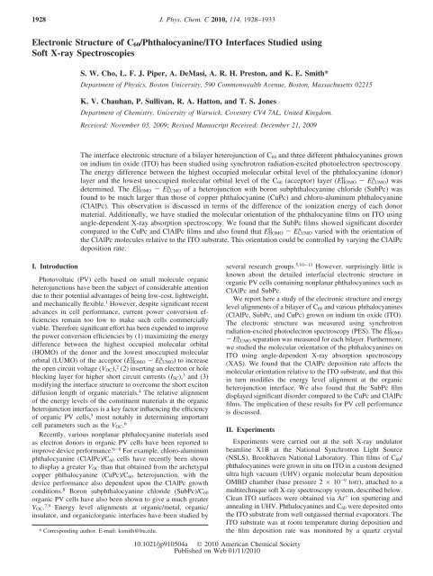
Figure 1. Molecular structures and the C 1s core-level photoemission<br />
spectra from thin films <strong>of</strong> CuPc, ClAlPc, and SubPc. hνexcite ) 750<br />
eV.<br />
microbalance. Two different deposition rates for ClAlPc were<br />
used: 0.5 and 1.5 Å/s. The deposition rate for SubPc and CuPc<br />
was 1.5 Å/s, and the rate for <strong>C60</strong> was 0.5 Å/s. After deposition,<br />
the samples were transferred under vacuum into the spectrometer<br />
chamber (base pressure 2 × 10 -10 torr).<br />
Beamline X1B is equipped with a spherical grating monochromator,<br />
and the photon beam is focused to an approximate<br />
60 × 40 µm spot on the sample. C and N K-edge XAS spectra<br />
were recorded by the sample drain current technique to obtain<br />
the total electron yield (TEY) and were normalized to the current<br />
from a Au coated mesh positioned in the incident photon beam.<br />
PES spectra were recorded using a Scienta 100 mm hemispherical<br />
electron analyzer. The C 1s core-level spectra were recorded<br />
using an incident photon energy <strong>of</strong> 750 eV. The secondary<br />
electron cut<strong>of</strong>f and valence band spectra were recorded using<br />
an incident photon energy <strong>of</strong> 250 eV. The onset <strong>of</strong> photoemission<br />
(and hence the sample work function) was measured with<br />
a negative bias (-9 V) applied to the sample in order to exceed<br />
the work function <strong>of</strong> the detector. Spectra are referenced relative<br />
to the Fermi level (EF) <strong>of</strong> an atomically clean gold foil in contact<br />
with the sample.<br />
III. Results and Discussions<br />
i. Molecular <strong>Structure</strong> and C 1s Core-Level Spectra.<br />
Figure 1 displays schematics <strong>of</strong> the molecular structure and C<br />
1s core level photoemission spectra from 15 nm thick CuPc,<br />
ClAlPc, and SubPc films grown in situ on <strong>ITO</strong> as described<br />
above. The line shapes <strong>of</strong> these spectra were analyzed by a<br />
standard least-squares fitting scheme using a convolution <strong>of</strong><br />
Gaussian and Lorentzian peaks. The width <strong>of</strong> the Lorentzian<br />
peaks was assumed to be the same for each component. We<br />
obtain a full width at half-maximum (fwhm) for the Lorentzian<br />
<strong>of</strong> about 0.2 eV. The fwhm for the Gaussian resulting from the<br />
fitting procedure is 0.90-0.98 eV and is similar for each<br />
component. As illustrated in Figure 1, the CuPc molecule has<br />
a Cu atom in the center <strong>of</strong> the macrocycle, whereas the ClAlPc<br />
molecule has an Al atom in the center <strong>of</strong> the phthalocyanine<br />
and bonded to an out-<strong>of</strong>-plane Cl atom. In contrast, SubPc is<br />
composed <strong>of</strong> three diiminoisoindole rings N-bonded around the<br />
B atom in the center position, which is bonded to an out-<strong>of</strong>plane<br />
Cl atom. Each C 1s spectrum in Figure 1 from these<br />
phthalocyanines consist <strong>of</strong> four components. Two core-level<br />
states (C-C and C-N) are clearly observed along with two<br />
accompanying shakeup satellites associated with kinetic energy<br />
loss <strong>of</strong> photoelectrons due to simultaneously excited π-π*<br />
transitions (i.e., HOMO to LUMO transitions). For CuPc, the<br />
energy splitting between the aromatic carbon <strong>of</strong> the benzene<br />
rings (C-C) and pyrrole carbon linked to nitrogen (C-N) is<br />
∼1.3 eV. The shakeup satellite features <strong>of</strong> CuPc were each<br />
described by Gaussian peaks at a distance <strong>of</strong> ∼1.9 eV from the<br />
corresponding main line. Our measurements agree with earlier<br />
reported photoemission studies. 14<br />
Note that the separation in energy <strong>of</strong> the shakeup satellites<br />
from the main lines corresponds to the transport gap (E T ). Our<br />
value <strong>of</strong> 1.9 eV for E T for CuPc agrees well with the previously<br />
reported value. 15 In general, the optical band gap (E OPT ) is less<br />
than the E T and the difference is the exciton binding energy<br />
(E EX ), i.e. 16<br />
E OPT ) E T - E EX<br />
Using the previously reported E OPT for CuPc (1.63 eV), 6 eq<br />
1 gives E EX ) 0.27 eV for CuPc. The C 1s core-level spectra<br />
<strong>of</strong> ClAlPc show an energetic splitting <strong>of</strong> ∼1.4 eV between the<br />
aromatic and pyrrole carbon atoms, and the shakeup satellite<br />
separation at 1.9 eV is the same as that <strong>of</strong> CuPc. Thus E T for<br />
ClAlPc is also approximately 1.9 eV. The reported E OPT <strong>of</strong><br />
ClAlPc is 1.66 eV, also very similar to that <strong>of</strong> CuPc. 17 In sharp<br />
contrast, the shakeup satellite separation in SubPc is much larger<br />
at 2.4 eV. Thus SubPc has the largest E T between the HOMO<br />
and the LUMO states, consistent with previously reported E OPT<br />
values. 9,10,17 From these results, we obtain E T ) 2.4 eV and<br />
E EX ) 0.4 eV for SubPc. The energetic splitting <strong>of</strong> ∼1.6 eV<br />
between the aromatic and pyrrole carbon for SubPc is larger<br />
than that <strong>of</strong> CuPc and ClAlPc. This indicates that the<br />
nitrogen-carbon bonding in SubPc is stronger than the other<br />
phthalocyanines due to the different molecular structure.<br />
ii. <strong>Electronic</strong> <strong>Structure</strong> <strong>of</strong> <strong>C60</strong>/ClAlPc/<strong>ITO</strong>. Figure 2a<br />
shows the experimental geometry for the angle-dependent XAS<br />
measurements. We used a polished polycrystalline <strong>ITO</strong> substrate,<br />
but even on a relatively rough substrate, Pc forms well-ordered<br />
films. 18 Figure 2b presents N K-edge XAS spectra from ClAlPc<br />
grown at 0.5 Å/s on <strong>ITO</strong>. Spectra recorded with the p-polarized<br />
radiation incident at θ ) 25° and 90° to the sample surface are<br />
shown. The intensity (I)<strong>of</strong>theπ* resonance in the XAS spectra<br />
(photon energy range 397-405 eV) is related to the tilt angle<br />
R <strong>of</strong> the ClAlPc molecular plane with respect to the substrate<br />
plane and the photon incidence angle θ by 19<br />
(1)<br />
I(θ) ∝ 1 + 1<br />
2 (3 cos2 θ - 1)(3 cos 2 R-1) (2)<br />
Using this formula, we estimate the azimuthal average tilt<br />
angle R to be 42° ( 5° for ClAlPc deposited at 0.5 Å/s on<br />
<strong>ITO</strong>. Figure 2c presents the equivalent XAS spectra to Figure<br />
2b but for a ClAlPc film grown at 1.5 Å/s on <strong>ITO</strong>. A much<br />
higher intensity for the π* resonance at an incidence angle <strong>of</strong><br />
25° is observed compared to that obtained from a film grown<br />
at 0.5 Å/s (Figure 2b). This indicates that the molecular<br />
orientation is different from the film grown at 0.5 Å/s. The tilt<br />
angle R is estimated to be 38° ( 5° for this faster grown film.
1930 J. Phys. Chem. C, Vol. 114, No. 4, 2010 Cho et al.<br />
Figure 2. (a) Experimental XAS geometry; N K-edge XAS spectra<br />
for ClAlPc grown on <strong>ITO</strong> at (b) 0.5 and (c) 1.5 Å/s.<br />
Figure 3. (a) Schematic illustration <strong>of</strong> some <strong>of</strong> the important<br />
parameters derived from PES characterization <strong>of</strong> surfaces and interfaces.<br />
(b) An energy-level diagram for a generic junction formed between an<br />
organic film and an <strong>ITO</strong> substrate.<br />
Despite the relatively large error bars in this measurement, it is<br />
clear that the deposition rate affects the average ClAlPc<br />
molecular orientation.<br />
Figure 3 illustrates the procedure used for the determination<br />
<strong>of</strong> energy-level alignment at the interface. The basic equation<br />
used in interpreting photoelectron spectra is<br />
E B ) hν - E k - Φ (3)<br />
The photon energy (hν) is known and the photoelectron<br />
kinetic energy (Ek) is measured in order to deduce the binding<br />
energy (EB) referenced to EF. When hν is known, the work<br />
function (Φ) can be obtained from the measured energy <strong>of</strong> the<br />
secondary-electron cut<strong>of</strong>f (Ecut<strong>of</strong>f), i.e.<br />
Φ ) hν - Ecut<strong>of</strong>f (4)<br />
The change in the work function, ∆Φ, can then be tracked<br />
by measuring Ecut<strong>of</strong>f after a deposition step. Therefore, the shift<br />
Figure 4. Valence band PES spectra recorded near EF after the<br />
deposition <strong>of</strong> each layer <strong>of</strong> (a) <strong>C60</strong>/ClAlPc (0.5 Å/s)/<strong>ITO</strong> and (b) <strong>C60</strong>/<br />
ClAlPc (1.5 Å/s)/<strong>ITO</strong>.<br />
<strong>of</strong> this Ecut<strong>of</strong>f indicates the magnitude <strong>of</strong> the interfacial dipole,<br />
which is equal to increasing or decreasing the work function. 20,21<br />
Similarly, the ionization potential (IP) can be obtained from<br />
Ecut<strong>of</strong>f and the HOMO onset (EHOMO)<br />
IP ) hν - (E cut<strong>of</strong>f - E HOMO ) (5)<br />
Figure 4 presents valence band photoemission spectra collected<br />
within 5 eV <strong>of</strong> EF, recorded from <strong>ITO</strong>, the ClAlPc film<br />
grown on <strong>ITO</strong>, and then the <strong>C60</strong>/ClAlPc/<strong>ITO</strong> bilayer [spectra<br />
from the 0.5 Å/s ClAlPc deposition rate films are presented in<br />
Figure 4a and from the 1.5 Å/s ClAlPc deposition rate films in<br />
Figure 4b]. The valence band spectra from the different ClAlPc<br />
films are clearly different. This is due to the different relative<br />
molecular orientation. Kera et al. have reported that the<br />
molecular orientation <strong>of</strong> the outmost layer affects the shape <strong>of</strong><br />
photoemission spectra from the valence band and HOMO in<br />
ClAlPc. 22 If the direction <strong>of</strong> the chlorine bond in the outermost<br />
layer is toward the substrate, the photoemission intensity <strong>of</strong><br />
π-related molecular orbitals (the HOMO and the feature at ∼3.5<br />
eV) is very weak. Furthermore the shape <strong>of</strong> the HOMO PES<br />
spectrum is also different depending on the direction <strong>of</strong> the<br />
chlorine bond in the outermost layer. 22 The HOMO onset <strong>of</strong><br />
the ClAlPc layer deposited at the 0.5 Å/s rate on <strong>ITO</strong> was 0.35<br />
eV below EF and that <strong>of</strong> the ClAlPc layer deposited at the 1.5<br />
Å/s rate was 0.55 eV. These HOMO onsets <strong>of</strong> the donor<br />
(ClAlPc) affect the EHOMO<br />
D - ELUMO<br />
A and ultimately the measured<br />
VOC <strong>of</strong> an organic PV cell based on this donor-acceptor<br />
heterojunction. The HOMO onset <strong>of</strong> the <strong>C60</strong> was 1.40 eV below<br />
the Fermi level in both cases. Consequently, it is reasonable to<br />
assume that the LUMO onset <strong>of</strong> the acceptor (<strong>C60</strong>) is the same<br />
in both systems.<br />
The determined energy level diagrams derived from analyzing<br />
the spectral changes using the method illustrated in Figure 3,<br />
are presented in Figure 5. We have used a band gap between<br />
the HOMO and the LUMO <strong>of</strong> 1.9 eV for ClAlPc (as determined<br />
from the satellite structure in Figure 1) and the previously<br />
reported band gap <strong>of</strong> 2.0 eV for <strong>C60</strong>. 6 The measured ionization<br />
potentials <strong>of</strong> ClAlPc and <strong>C60</strong> are then estimated to be about<br />
5.25-5.35 and 6.3 eV, respectively. The measured EHOMO<br />
D -<br />
A is 0.95 eV in the heterojunction with the 0.5 Å/s ClAlPc<br />
ELUMO<br />
deposition rate and it increases to 1.15 eV in that with the 1.5<br />
Å/s rate due to the different HOMO onset <strong>of</strong> the ClAlPc layer.
<strong>C60</strong>/<strong>Phthalocyanine</strong>/<strong>ITO</strong> Interfaces J. Phys. Chem. C, Vol. 114, No. 4, 2010 1931<br />
Figure 5. Energy level alignment <strong>of</strong> (a) <strong>C60</strong>/ClAlPc (0.5 Å/s)/<strong>ITO</strong><br />
and (b) <strong>C60</strong>/ClAlPc D A (1.5 Å/s)/<strong>ITO</strong>. The EHOMO - ELUMO energetic<br />
separation for both interfaces is highlighted (dashed oval line).<br />
In the context <strong>of</strong> an organic PV cell based on this heterojunction,<br />
this implies that the VOC would vary with the ClAlPc deposition<br />
rate, as has recently been reported for a ClAlPc PV cell. 8<br />
To probe this observation further, the interface dipoles <strong>of</strong> the<br />
ClAlPc/<strong>ITO</strong> were compared to each other. The magnitude <strong>of</strong><br />
the interface dipole <strong>of</strong> the ClAlPc/<strong>ITO</strong> heterojunction formed<br />
with the 0.5 Å/s deposition rate (0.7 eV) is larger than that grown<br />
at the faster rate (0.3 eV). In the former case, the large interface<br />
dipole pulls the ClAlPc HOMO up toward EF. The ionization<br />
energy, corresponding to the energy position <strong>of</strong> the HOMO<br />
relative to the vacuum level, is a unique property <strong>of</strong> materials. 11<br />
The origin <strong>of</strong> an interfacial dipole is the charge redistribution<br />
between the organic molecule and the substrate. 11,23 Therefore<br />
the observation <strong>of</strong> different interface dipoles as a function <strong>of</strong><br />
deposition rate can be understood by the different molecular<br />
density <strong>of</strong> the ClAlPc at the interface. A higher molecular<br />
density means more molecules interact with the substrate and<br />
results in a larger interface dipole. The relative molecular density<br />
can be estimated by the molecular orientation derived from our<br />
angle dependent XAS spectra. The molecular layer with a larger<br />
value <strong>of</strong> R has a higher density. 24 Therefore the interface<br />
between the ClAlPc layer deposited at 0.5 Å/s on <strong>ITO</strong> has a<br />
larger interface dipole than that from the film grown at 1.5 Å/s.<br />
Thus different molecular orientations resulting from different<br />
deposition rates influence the interface electronic properties that<br />
are most important for the efficient design and operation <strong>of</strong><br />
organic PV cells fabricated with molecular materials.<br />
iii. <strong>Electronic</strong> <strong>Structure</strong> <strong>of</strong> <strong>C60</strong>/SubPc/<strong>ITO</strong>. Figure 6a<br />
shows how the work function (as measured from Ecut<strong>of</strong>f in PES)<br />
varies with the thickness <strong>of</strong> a SubPc film and with subsequent<br />
deposition <strong>of</strong> a <strong>C60</strong> film on the SubPc layer. Φ increases by 0.2<br />
eV upon deposition <strong>of</strong> 5 nm <strong>of</strong> SubPc. This is attributed to the<br />
formation <strong>of</strong> an interface dipole. 20 However, as more SubPc<br />
was deposited, Φ decreases by 0.2 eV, due to downward band<br />
bending (see below). Subsequent deposition <strong>of</strong> <strong>C60</strong> resulted in<br />
a shift <strong>of</strong> the interface dipole between <strong>C60</strong> and SubPc <strong>of</strong> 0.5 eV<br />
to higher energy.<br />
Figure 6b presents valence band photoemission spectra<br />
collected within 5 eV <strong>of</strong> EF from <strong>ITO</strong>, from the SubPc film<br />
grown on <strong>ITO</strong>, and then from the <strong>C60</strong>/SubPc/<strong>ITO</strong> bilayer. As<br />
thicker SubPc films are deposited, it is clear that the SubPc<br />
HOMO shifts toward higher binding energies and the total shift<br />
Figure 6. (a) Change in the onset <strong>of</strong> secondary electron PES spectra<br />
after the deposition <strong>of</strong> each layer <strong>of</strong> <strong>C60</strong>/SubPc/<strong>ITO</strong>. (b) Valence band<br />
PES spectra recorded near EF after the deposition <strong>of</strong> each layer <strong>of</strong> <strong>C60</strong>/<br />
SubPc/<strong>ITO</strong><br />
reaches 0.2 eV at saturation. This confirms that downward band<br />
bending occurs at the SubPc/<strong>ITO</strong> interface as implied by Figure<br />
6a. The saturation HOMO onset <strong>of</strong> the SubPc layer was 1.3 eV<br />
below EF. These HOMO onsets <strong>of</strong> the donor affect the EHOMO<br />
D<br />
- ELUMO<br />
A and ultimately the measured VOC <strong>of</strong> an organic PV<br />
cell based on this donor-acceptor heterojunction. On the other<br />
hand, there was no shift in the HOMO energy for the <strong>C60</strong>/SubPc<br />
interface. The HOMO onset <strong>of</strong> the <strong>C60</strong> layer deposited on the<br />
SubPc layer was measured as 1.55 eV.<br />
The energy level diagram derived from analyzing the spectral<br />
changes shown in Figure 6 is presented in Figure 7a. Also<br />
included in Figure 7 is the energy level diagram <strong>of</strong> <strong>C60</strong>/ClAlPc/<br />
<strong>ITO</strong> obtained from Figure 5b and the corresponding measured<br />
energy level diagram for <strong>C60</strong>/CuPc/<strong>ITO</strong>. We have used the<br />
previously obtained band gap between the HOMO and the<br />
LUMO <strong>of</strong> 2.4 for SubPc. 9 The SuPb/<strong>C60</strong> heterojunction, which<br />
showed the largest VOC in PV cells, has the largest EHOMO<br />
D -<br />
A value (1.75 eV). The measured EHOMO<br />
ELUMO<br />
D - ELUMO<br />
A in<br />
ClAlPc/<strong>C60</strong> was 1.15 eV and was 1.00 eV for CuPc/<strong>C60</strong>. These<br />
differences in ED HOMO -EA LUMO values are predicted to lead to<br />
enhanced values <strong>of</strong> VOC for the SubPc-based PVs. However, a<br />
correction term between real VOC and EHOMO<br />
D - ELUMO<br />
A may be<br />
needed to account for voltage losses in the device due to large<br />
diode quality factors, high reverse saturation currents, low fielddependent<br />
mobilities <strong>of</strong> charge carriers, and voltage losses at<br />
the collection electrodes. 6 There are several factors, which can<br />
control EHOMO<br />
D - ELUMO<br />
A at a donor/acceptor interface, such as<br />
the ionization potential <strong>of</strong> a donor, the electron affinity <strong>of</strong> an<br />
acceptor, the formation <strong>of</strong> interface dipoles and charge redistribution<br />
across the interfaces. 12,25 According to the traditional<br />
Schottky-Mott model, EHOMO<br />
D - ELUMO<br />
A is the difference<br />
between the ionization potential <strong>of</strong> a donor and the electron<br />
affinity <strong>of</strong> an acceptor. In reality, a dipole layer is formed<br />
directly at the donor/acceptor interfaces. An interface dipole<br />
with its positive pole pointing toward the donor and its negative<br />
pole pointing toward the acceptor layer will increase the EHOMO<br />
D<br />
- ELUMO<br />
A separation, because the interface dipole results in a<br />
shifting <strong>of</strong> the molecular orbitals <strong>of</strong> the donor toward high<br />
binding energy and that <strong>of</strong> the acceptor in the opposite direction.
1932 J. Phys. Chem. C, Vol. 114, No. 4, 2010 Cho et al.<br />
Figure 7. Energy level alignment <strong>of</strong> (a) <strong>C60</strong>/SubPc/<strong>ITO</strong>, D A (b) <strong>C60</strong>/ClAlPc/<strong>ITO</strong>, and (c) <strong>C60</strong>/CuPc/<strong>ITO</strong>. (d) Variation <strong>of</strong> EHOMO - ELUMO and VOC as<br />
a function <strong>of</strong> the ionization potential <strong>of</strong> the three Pc donors.<br />
In this study, the measured ionization potentials <strong>of</strong> SubPc,<br />
ClAlPc, and CuPc are estimated to be about 5.65, 5.25, and<br />
4.95 eV, respectively. SubPc showed the largest EHOMO<br />
D - ELUMO<br />
A<br />
and has the largest ionization potential, whereas CuPc showed<br />
the smallest EHOMO<br />
D - ELUMO<br />
A and has the smallest ionization<br />
potential. These results agree with previous reported device<br />
studies. 7,8 Although each interface <strong>of</strong> the donor (Pc) and acceptor<br />
(<strong>C60</strong>) has a different interface dipole which will act to increase<br />
EHOMO<br />
D - ELUMO<br />
A , we find that this difference is small compared<br />
to that <strong>of</strong> the ionization potentials <strong>of</strong> the donors. Figure 7(d)<br />
shows the relationship between the ionization potential <strong>of</strong> the<br />
donor and both EHOMO<br />
D - ELUMO<br />
A , and VOC as measured from<br />
devices made from similar heterojunctions. The difference<br />
between the maximum achievable VOC and EHOMO<br />
D - ELUMO<br />
A is<br />
the energy needed to dissociate the bound electron-hole pair<br />
at the donor/acceptor interface immediately after its formation<br />
via photoinduced charge transfer. 26 This figure confirms that<br />
the VOC <strong>of</strong> organic PV cells based on these different molecular<br />
heterojunctions is related to the ionization potential <strong>of</strong> the<br />
specific donor materials used.<br />
It is important to note that a SubPc/<strong>C60</strong> PV cells based on a<br />
conventional heterojunction structure with similarthicknesses <strong>of</strong><br />
the donor and acceptor layers demonstrated only slightly higher<br />
VOC values than those obtained from a CuPc/<strong>C60</strong> PV cell, with<br />
a severely reduced ISC. When a much thinner SubPc donor layer<br />
was used, the device performance (especially the VOC) dramatically<br />
improved. 7 In order to find the origin <strong>of</strong> the lower ISC we<br />
studied the molecular orientation <strong>of</strong> CuPc and SubPc on <strong>ITO</strong><br />
using angle-dependent XAS. Figure 8a presents N K-edge XAS<br />
spectra from CuPc on <strong>ITO</strong>. Spectra recorded with the p-polarized<br />
radiation incident at θ ) 25° and 90° to the sample surface are<br />
Figure 8. (a) N K-edge XAS spectra for CuPc on <strong>ITO</strong> and (b) SubPc<br />
on <strong>ITO</strong>.<br />
shown. It can be seen that the relative intensity <strong>of</strong> the π* and<br />
σ* resonances change significantly with the incident angle. The<br />
CuPc molecules are well ordered on <strong>ITO</strong> substrates, as reported<br />
previously. 18 Using eq 2, we estimate the average tilt angle R<br />
to be 70° ( 5° for CuPc on <strong>ITO</strong>. Figure 8b presents N K-edge<br />
XAS spectra from SubPc on <strong>ITO</strong>. In this case, the π* and σ*<br />
peak intensity is independent <strong>of</strong> the incident angle. A relatively<br />
weak angular dependence indicates significant disorder in the<br />
film, 27 and the molecular disorder results in low field-effect<br />
mobilities. 28 Gommans et al. has also reported molecular
<strong>C60</strong>/<strong>Phthalocyanine</strong>/<strong>ITO</strong> Interfaces J. Phys. Chem. C, Vol. 114, No. 4, 2010 1933<br />
disorder for SubPc on <strong>ITO</strong> on the basis <strong>of</strong> microscopy studies. 29<br />
Since SubPc molecules on <strong>ITO</strong> are disordered, a much lower<br />
SubPc layer thickness must be used to enhance ISC and for<br />
optimal device performance.<br />
IV. Conclusions<br />
The interface electronic structure <strong>of</strong> a bilayer <strong>of</strong> <strong>C60</strong> and three<br />
phthalocyanines grown on <strong>ITO</strong> has been studied using synchrotron<br />
radiation-excited photoelectron spectroscopy. The<br />
EHOMO<br />
D - ELUMO<br />
A <strong>of</strong> a heterojunction with SubPc was found to<br />
be 1.75 eV, whereas those with CuPc and ClAlPc were 1.00<br />
and 0.95-1.15 eV, respectively. This difference was explained<br />
in terms <strong>of</strong> the difference <strong>of</strong> the ionization energy <strong>of</strong> each<br />
material. Additionally, we have studied the molecular orientation<br />
<strong>of</strong> the same phthalocyanines on <strong>ITO</strong> using angle-dependent<br />
XAS. For ClAlPc, we found that the orientation <strong>of</strong> the ClAlPc<br />
molecules relative to the <strong>ITO</strong> substrate could be controlled by<br />
varying the ClAlPc deposition rate. The SubPc film showed<br />
significant disorder compared to the CuPc and ClAlPc films<br />
and the molecular disorder results in low charge mobility.<br />
Acknowledgment. This work was supported in part by the<br />
NSF under Grant No. CHE-0807368. The NSLS is supported<br />
by the U.S. Department <strong>of</strong> Energy, Office <strong>of</strong> Science, Office <strong>of</strong><br />
Basic Energy Sciences, under Contract No. DE-AC02-<br />
98CH10886. Financial support from the EPSRC, U.K. is also<br />
acknowledged through the SUPERGEN Excitonic Solar Cell<br />
Consortium programme. R.A.H. is supported by a Royal<br />
Academy <strong>of</strong> Engineering/EPSRC Research Fellowship.<br />
References and Notes<br />
(1) Forrest, S. R. Nature 2004, 428, 911. Forrest, S. R. Mater. Res.<br />
Soc. Bull. 2005, 30, 28. Xue, J.; Uchida, S.; Rand, B. P.; Forrest, S. R.<br />
Appl. Phys. Lett. 2004, 84, 3013.<br />
(2) Brabec, C. J.; Cravino, A.; Meissner, D.; Sariciftci, N. S.; Fromherz,<br />
T.; Rispens, M. T.; Sanchez, L.; Hummelen, J. C. AdV. Funct. Mater. 2001,<br />
11, 374.<br />
(3) Boucle, J.; Ravirajan, P.; Nelson, J. J. Mater. Chem. 2007, 17, 3141.<br />
(4) Nanditha, D. M.; Dissanayake, M.; Adikaari, A. A. D. T.; Curry,<br />
R. J.; Hatton, R. A.; Silva, S. R. P. Appl. Phys. Lett. 2007, 90, 253502.<br />
(5) Betti, M. G.; Kanjilal, A.; Mariani, C.; Vazquez, H.; Dappe, Y. J.;<br />
Ortega, J.; Flores, F. Phys. ReV. Lett. 2008, 100, 027601. Molodtsova, O. V.;<br />
Grobosch, M.; Knupfer, M.; Aristov, V. Y. Appl. Phys. Lett. 2007, 91,<br />
244103.<br />
(6) Brumbach, M.; Placencia, D.; Armstrong, N. R. J. Phys. Chem. C<br />
2008, 112, 3142.<br />
(7) Mutolo, K. L.; Mayo, E. I.; Rand, B. P.; Forrest, S. R.; Thompson,<br />
M. E. J. Am. Chem. Soc. 2006, 128, 8108.<br />
(8) Bailey-Salzman, R. F.; Rand, B. P.; Forrest, S. R. Appl. Phys. Lett.<br />
2007, 91, 013508.<br />
(9) Kumar, H.; Kumar, P.; Bhardwaj, R.; Sharma, G. D.; Chand, S.;<br />
Jain, S. C.; Kumar, V. J. Phys. D Appl. Phys. 2009, 42, 015103.<br />
(10) Hill, I. G.; Rajagopal, A.; Kahn, A. J. Appl. Phys. 1998, 84, 3236.<br />
(11) Ishii, H.; Sugiyama, K.; Ito, E.; Seki, K. AdV. Mater. 1999, 11,<br />
605.<br />
(12) Schlaf, R.; Parkinson, B. A.; Lee, P. A.; Nebesny, K. W.;<br />
Armstrong, N. R. J. Phys. Chem. 1999, 103, 2984.<br />
(13) Watkins, N. J.; Zorba, S.; Gao, Y. J. Appl. Phys. 2004, 96, 425.<br />
Cho, S. W.; Yoo, K. H.; Jeong, K.; Whang, C. N.; Yi, Y.; Noh, M. Appl.<br />
Phys. Lett. 2007, 91.<br />
(14) Schwieger, T.; Peisert, H.; Golden, M. S.; Knupfer, M.; Fink, J.<br />
Phys. ReV. B2002, 66, 155207. Cho, S. W.; Yi, Y.; Noh, M.; Cho, M. H.;<br />
Yoo, K. H.; Jeong, K.; Whang, C. N. Synt. Met. 2008, 158, 539. Peisert,<br />
H.; Knupfer, M.; Fink, J. Surf. Sci. 2002, 515, 491.<br />
(15) Conjugated Polymers and Molecular Interfaces: Science and<br />
Technology for Photonic and Optoelectronic Applications; Salaneck, W. R.,<br />
Seki, K., Kahn, A., Pireaux, J. J., Eds.; Dekker: New York, 2002.<br />
(16) Hill, I. G.; Kahn, A.; Soos, Z. G.; Pascal, R. A., Jr. Chem. Phys.<br />
Lett. 2000, 327, 181.<br />
(17) Roy, M. S.; Balraju, P.; Deol, Y. S.; Sharma, S. K.; Sharma, G. D.<br />
J. Mat. Sci. 2008, 43, 5551.<br />
(18) Peisert, H.; Schwieger, T.; Auerhammer, J. M.; Knupfer, M.;<br />
Golden, M. S.; Fink, J.; Bressler, P. R.; Mast, M. J. Appl. Phys. 2001, 90,<br />
466.<br />
(19) Stöhr, J. NEXAFS Spectroscopy; Springer: Berlin, 1992.<br />
(20) Lee, S. T.; Hou, X. Y.; Mason, M. G.; Tang, C. W. Appl. Phys.<br />
Lett. 1998, 72, 1593.<br />
(21) Shen, C.; Kahn, A. Org. Elec. 2001, 2, 89.<br />
(22) Kera, S.; Yamane, H.; Honda, H.; Fukagawa, H.; Okudaira, K. K.;<br />
Ueno, N. Surf. Sci. 2004, 566, 571.<br />
(23) Crispin, X.; Geskin, V.; Crispin, A.; Cornil, J.; Lazzaroni, R.;<br />
Salaneck, W. R.; Bredas, J. L. J. Am. Chem. Soc. 2002, 124, 8131.<br />
(24) Chen, W.; Chen, S.; Huang, H.; Qi, D. C.; Gao, X. Y.; Wee, A. T. S.<br />
Appl. Phys. Lett. 2008, 92, 063308.<br />
(25) Alloway, D. M.; H<strong>of</strong>mann, M.; Smith, D. L.; Gruhn, N. E.; Graham,<br />
A. L.; Colorado, R.; Wysocki, V. H.; Lee, T. R.; Lee, P. A.; Armstrong,<br />
N. R. J. Phys. Chem. B 2003, 107, 11690. Zhou, X.; Pfeiffer, M.; Blochwitz,<br />
J.; Werner, A.; Nollau, A.; Fritz, T.; Leo, K. Appl. Phys. Lett. 2001, 78,<br />
410.<br />
(26) Rand, B. P.; Burk, D. P.; Forrest, S. R. Phys. ReV. B2007, 75,<br />
115327.<br />
(27) Alfredsson, Y.; Ahlund, J.; Nilson, K.; Kjeldgaard, L.; O’Shea, J. N.;<br />
Theobald, J.; Bao, Z.; Martensson, N.; Sandell, A.; Puglia, C.; Siegbahn,<br />
H. Thin Sol. Films 2005, 493, 13.<br />
(28) Li, L. Q.; Tang, Q. X.; Li, H. X.; Hu, W. P. J. Phys. Chem. B<br />
2008, 112, 10405.<br />
(29) Gommans, H.; Cheyns, D.; Aernouts, T.; Girotto, C.; Poortmans,<br />
J.; Heremans, P. AdV. Funct. Mater. 2007, 17, 2653.<br />
JP910504A