Broan 283603 Installation Instructions
Broan 283603 Installation Instructions
Broan 283603 Installation Instructions

You also want an ePaper? Increase the reach of your titles
YUMPU automatically turns print PDFs into web optimized ePapers that Google loves.
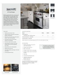
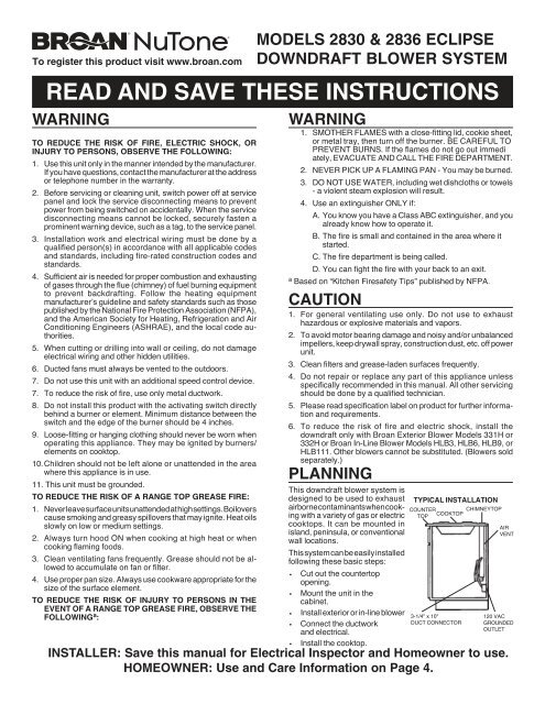
To register this product visit www.broan.comMODELS 2830 & 2836 ECLIPSEDOWNDRAFT BLOWER SYSTEMREAD AND SAVE THESE INSTRUCTIONSWARNINGTO REDUCE THE RISK OF FIRE, ELECTRIC SHOCK, ORINJURY TO PERSONS, OBSERVE THE FOLLOWING:1. Use this unit only in the manner intended by the manufacturer.If you have questions, contact the manufacturer at the addressor telephone number in the warranty.2. Before servicing or cleaning unit, switch power off at servicepanel and lock the service disconnecting means to preventpower from being switched on accidentally. When the servicedisconnecting means cannot be locked, securely fasten aprominent warning device, such as a tag, to the service panel.3. <strong>Installation</strong> work and electrical wiring must be done by aqualified person(s) in accordance with all applicable codesand standards, including fire-rated construction codes andstandards.4. Sufficient air is needed for proper combustion and exhaustingof gases through the flue (chimney) of fuel burning equipmentto prevent backdrafting. Follow the heating equipmentmanufacturer’s guideline and safety standards such as thosepublished by the National Fire Protection Association (NFPA),and the American Society for Heating, Refrigeration and AirConditioning Engineers (ASHRAE), and the local code authorities.5. When cutting or drilling into wall or ceiling, do not damageelectrical wiring and other hidden utilities.6. Ducted fans must always be vented to the outdoors.7. Do not use this unit with an additional speed control device.7. To reduce the risk of fire, use only metal ductwork.8. Do not install this product with the activating switch directlybehind a burner or element. Minimum distance between theswitch and the edge of the burner should be 4 inches.9. Loose-fitting or hanging clothing should never be worn whenoperating this appliance. They may be ignited by burners/elements on cooktop.10. Children should not be left alone or unattended in the areawhere this appliance is in use.11. This unit must be grounded.TO REDUCE THE RISK OF A RANGE TOP GREASE FIRE:1. Never leave surface units unattended at high settings. Boiloverscause smoking and greasy spillovers that may ignite. Heat oilsslowly on low or medium settings.2. Always turn hood ON when cooking at high heat or whencooking flaming foods.3. Clean ventilating fans frequently. Grease should not be allowedto accumulate on fan or filter.4. Use proper pan size. Always use cookware appropriate for thesize of the surface element.TO REDUCE THE RISK OF INJURY TO PERSONS IN THEEVENT OF A RANGE TOP GREASE FIRE, OBSERVE THEFOLLOWING a :WARNING1. SMOTHER FLAMES with a close-fitting lid, cookie sheet,or metal tray, then turn off the burner. BE CAREFUL TOPREVENT BURNS. If the flames do not go out immediately, EVACUATE AND CALL THE FIRE DEPARTMENT.2. NEVER PICK UP A FLAMING PAN - You may be burned.3. DO NOT USE WATER, including wet dishcloths or towels- a violent steam explosion will result.4. Use an extinguisher ONLY if:A. You know you have a Class ABC extinguisher, and youalready know how to operate it.B. The fire is small and contained in the area where itstarted.C. The fire department is being called.D. You can fight the fire with your back to an exit.aBased on “Kitchen Firesafety Tips” published by NFPA.CAUTION1. For general ventilating use only. Do not use to exhausthazardous or explosive materials and vapors.2. To avoid motor bearing damage and noisy and/or unbalancedimpellers, keep drywall spray, construction dust, etc. off powerunit.3. Clean filters and grease-laden surfaces frequently.4. Do not repair or replace any part of this appliance unlessspecifically recommended in this manual. All other servicingshould be done by a qualified technician.5. Please read specification label on product for further informationand requirements.6. To reduce the risk of fire and electric shock, install thedowndraft only with <strong>Broan</strong> Exterior Blower Models 331H or332H or <strong>Broan</strong> In-Line Blower Models HLB3, HLB6, HLB9, orHLB111. Other blowers cannot be substituted. (Blowers soldseparately.)PLANNINGThis downdraft blower system isdesigned to be used to exhaustairborne contaminants when cookingwith a variety of gas or electriccooktops. It can be mounted inisland, peninsula, or conventionalwall locations.This system can be easily installedfollowing these basic steps:• Cut out the countertopopening.• Mount the unit in thecabinet.• Install exterior or in-line blower• Connect the ductworkand electrical.• Install the cooktop.TYPICAL INSTALLATIONCOUNTERCHIMNEYTOPTOPCOOKTOPAIRVENT3-1/4" x 10"DUCT CONNECTOR120 VACGROUNDEDOUTLETINSTALLER: Save this manual for Electrical Inspector and Homeowner to use.HOMEOWNER: Use and Care Information on Page 4.
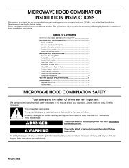
PLANNING - (continued)PLAN THE DUCTWORKNote: The high level of air flow of this appliance may affect the gasflame on some types of gas cooktops. This is NORMAL and willcause no harm, but can be corrected by lowering the speed of theblower.SPECIFICATIONSVOLTS AMPS Hz. DISCHARGE120 6.0 MAX. 60 3-1/4 X 10Install downdraft with an exterior blower that draws 6.0 AMPS orless.TAKE MEASUREMENTS1. Refer to the cooktop installation instructions for dimensions ofcooktop, countertop cut-out, and cabinet requirements. TheModel 2830 will fit in most 30" wide cabinets and the Model2836 will fit in most 36" wide cabinets. However, it is recommendedthat oversized cabinets be used for easier installation.2. Cooktop depth can vary greatly from one to another. This maycause the fit of these two appliances to be rather tight.8" ROUNDELBOWEQUALS 6 FT. OFSTRAIGHT DUCT3-1/4" X 10"90 O ELBOW3-1/4" X 10"TO 8" RD.TRANSITIONEQUALS 2FT. OFSTRAIGHT DUCT8" - 10"INCREASER3-1/4" x 10"DISCHARGE1. This downdraft blower system is most efficient when used with10" round ductwork. Use a combination of elbows and transitions(shown below), closest to the downdraft, in order to getfrom 3" x 10" to 10" round as soon as possible.2. For best performance: Choose the ducting option which allowsthe shortest length of ductwork and a minimum number ofelbows and transitions. Check location of floor joists, wallstuds, electrical wiring or plumbing for possible interference.Pay special attention to the areas of potential interference highlightedabove. A countertop with (A) a raised lip and/or (B) abacksplash may not allow enough flat countertop for a properinstallation. Note that 2" of flat countertop is required behindcooktop and that 1-3/4" is necessary between the back edge of thecooktop and the inside of cabinet back.EQUALS 8FT. OFSTRAIGHT DUCT3. The system will operate most efficiently when the ductworkdoes not exceed 40 feet of equivalent duct. The illustrations,above, shows equivalent feet of elbows and transitions. Thenumber of feet of straight duct plus the equivalent feet oftransitions and/or elbows to be used should equal 40 feet orless.NOTE: The equivalent feet of various roof and wall caps hasbeen taken into consideration. Do not include them in thiscalculation.4. Refer to instructions packed with exterior blower or in-lineblower for additional information.PLAN THE WIRING1. The downdraft and exterior blower system normally draws 6AMPS and requires a 120 VAC, 60 Hz circuit.2. The unit has a 2 ft. long power cord with a 3-pronged plug. Planto provide a grounded outlet in a location which will allow theunit’s power cord to reach. (Note: If the Model 2830 is beinginstalled in a 30" wide cabinet or the Model 2836 is beinginstalled in a 36" wide cabinet, the outlet cannot be located onthe back wall of cabinet.) Outlet may also be wall-mounted,with access hole in cabinet.2
CUT COUNTERTOP OPENING1. Lay out and cut the cooktop cut-out far enough FORWARD sodowndraft will fit behind it.2. Set cooktop in place and slide it as far forward as possible.Center and square it with edges of countertop.INSTALL DUCTWORK & BLOWERBEFORE CUTTING HOLE IN CABINET FOR DUCT-WORK: Check for interference with floor joists, wall studs, electricalwiring or plumbing.OUTLETASSEMBLYCOLLARTRANSITIONELBOW3. Place the plastic template against the back flange of thecooktop and center it. Trace around template to mark thedowndraft opening.4. Remove cooktop from countertop.5. Cut downdraft opening. Be careful not to chip edges ofcountertop.MOUNT THE UNITMOUNTING SCREWS1. Set downdraft into opening. Extend leveling brackets to floorof cabinet so downdraft sits straight. (Note: Leveling bracketscan be removed and re-attached in other positions. Bottomflange may have to face inward in tight cabinet installations.)2. Secure the downdraft to the countertop as follows: Hold thedowndraft against the back of countertop cut-out and tighteningthe 2 mounting screws (one on each end of unit) onunderside of countertop. Use a wood shim between screw andunderside of granite countertops.3. Screw leveling brackets to bottom of cabinet. Tighten screwsholding leveling bracket to unit on each side.1. Cut hole in cabinet as well as holes in wall or floor asnecessary.2. Mount the exterior blower or in-line blower and work backtowards the cabinet, attaching all ductwork, elbows and transitionsas previously planned. Tape all ductwork connectionsto make them secure and air tight. Refer to instructions packedwith exterior blower or in-line blower for additional information.3. Connect ductwork (and transition, if required) to downdraft. Ifnecessary, LOOSEN nuts and screws that hold the blower inplace, and slide outlet assembly left or right to meet ductwork.Re-tighten screws and nuts.INSTALL ELECTRICAL WIRING1. Mount a standard wiring box, with 3-pronged grounded receptacle,inside the kitchen cabinet. Make sure the unit's powercord can easily reach it.2. Run appropriate power cable into cabinet and connect it toelectrical box and receptacle.3. Exterior blower may not exceed 6.0 Amp rating.4. Run 2-wire plus ground power cable from the remote blowerto wiring box on downdraft. Remove wire box cover and attachcable using proper certified or recognized connector. Userecognized wire connectors to connect wires. Make sure wirescannot come loose from connectors after assembly.5. Connect downdraft wiring to power cable from exterior or inlineblower. Wire black to black, white to white and green togreen or bare wire.6. Replace wiring box cover.3
WIRING DIAGRAM3. Remove switch cover from right end of air vent.4. Loosen the 2 screws holding the switch bracket in place.Position switch bracket so that activating switch just comes incontact with underside of switch membrane. Tighten screws.5. Replace switch cover, gently lower air vent into chimney, andplug in power cord. Re-connect electrical power and checkoperation.USE AND CAREAlways turn the downdraft blower on before you begin cooking toestablish an air flow in the kitchen. Let the blower run for a fewminutes to clean the air after you turn the cooktop off. This willkeep the whole kitchen cleaner and brighter.CONTROLSINSTALL COOKTOP1. Align the cooktop with the downdraft and fasten cooktop inplace.Accurate alignment of cooktop and downdraft is necessaryto ensure that there is no interference when air vent is raised andlowered. There should be a gap of 1/32"-1/16" between the backof the cooktop and the front of the downdraft cover.ADJUSTMENTThe downdraft is factory-adjusted for proper operation. However,shipping and handling may affect the position of the activatingswitch.To adjust position of activating switch:WARNING: To avoid possible electricalshock, personal injury or death -Disconnect electrical power.Turn the downdraft blower ON by pressing down on the activatingswitch. The air vent will rise.KNOBThe blower can be turned ON or OFF and its speed can beadjusted with the recessed knob on the right side of the air vent.1. If downdraft is plugged into electrical outlet, unplug it.2. Lift air vent straight up and cock it slightly so it remains in theUP position.SWITCHMEMBRANESCREWSTurn the downdraft blower OFF by pressing the activating switchagain. The air vent will go down and the blower will shut OFF.Note: For most convenient operation, set the blower to yourfavorite speed. The blower will come on to this speed wheneverthe activating switch is pressed and the air vent rises.SWITCHBRACKETSWITCHCOVER4
USE AND CARE - (Continued)CLEANINGWARNING: Always disconnect electricpower supply before cleaning unit.Use a mild detergent suitable for painted surfaces. DO NOT USEABRASIVE CLOTH, STEEL WOOL PADS, OR SCOURINGPOWDERS.Wash the 2 aluminum grease filters in a mild detergent solution ora dishwasher. Remove them from the air vent by grasping the tabat the top of each filter.Note: The filters are different sizes. Be sure to replace them asremoved, (wider one on the left), with tabs UP.SERVICINGWARNING: Always disconnect electricpower supply before servicing unit.It may be necessary to remove the outlet assembly from thecabinet in order to service components such as the blower motoror air vent mechanism.Disconnect power to the cooktop and remove it first. Reverse thesteps under “MOUNT THE UNIT” to remove the downdraft fromthe cabinet.Service parts are available from your local <strong>Broan</strong> distributor orfrom <strong>Broan</strong> Service Department, P.O. Box 140, Hartford, WI53027 Phone: 1-800-637-1453.5
SERVICE PARTSModels 2830 & 2836Downdraft Blower SystemsKEY NO. PART NUMBER DESCRIPTION QTY.1 93400038 Bushing, 7/8" 23 99400024 Bushing, Heyco, 1/2" 14 93470012 Roller 15 97011927 Switch Assembly, Up/Down 18 99360165 Knob 110 97009972 Lower Switch Bracket Assembly 111 97011293 Green Ground Wire 112 97010997 Wire Harness 116 98007642 Back-up Plate 117 98007780 Crank 118 98008168 Switch Cover 119 97011325 Chimney Assembly with Slide (Model HV303) 197011326 Chimney Assembly with Slide (Model HV363) 122 98008175 Outlet Extension 123 99710032 Spacer 224 97011259 Top Bracket Assembly, Right 125 97011260 Top Bracket Assembly, Left 126 97011322 Top, Stainless (30") 197011323 Top, Stainless (36") 128 97010999 Outlet Assembly 129 97011443 Gear Motor Cover 130 97010998 Air Box Assembly (30") 197011000 Air Box Assembly (36") 133 97009786 Filter Kit (30") (contains 2 filters) 197009787 Filter Kit (36") (contains 2 filters) 145 99090939 End Cap 146 99080590 Gearmotor 147 99110850 Slide Strip 349 99170245 Screw, #8-18 x .375 SLT HX WS HD 1650 99150471 Screw, #10-32 x .500 HX WS BDRH 251 99150526 Screw, #8-18 x .250 SA PH TRH 652 99150488 Screw, #8-18 x .500 No. 5 PH Trim 253 98008186 Cover, Air Box Opening 154 99260488 Nut, 10-24 455 98008174 Air Box Cover (30") 198008173 Air Box Cover (36") 156 97011500 Gearmotor Bracket Assembly 157 98008187 Leg Support 258 99200202 Screw, 1/4-20 x 1/2 SEMS 560 99150479 Screw, #8-32 x 1/2 PH HD MS 461 99160356 Screw, #10-24 x 3/8 SH WH LOCK 162 99160361 Screw, #10-24 x 3/8 PH FL HD LD 164 99260437 Nut, 10-24 HEX KEPS 666 99380633 U-Bolt, 10-24 167 99400060 Strain Relief 168 93260447 Nut, Hex Flange 170 98008415 Wire Channel Clamp 271 93270493 Wire Tie 374 99160384 Screw, 1/4-20 x 2.000 Hex. Hd. 275 99150415 #8-18 x .250 PH TR HD BPT 376 98008183 Outlet Box Cover 182 98008166 Cover - Gear Motor 184 99100503 Seal - Foam (30") 199100504 Seal - Foam (36") 1** 97011320 Chimney Assembly, Complete (30") (Includes KeyNos. 5, 8, 19, 45, 51, 52, & 71)** 97011321 Chimney Assembly, Complete (36") (Includes KeyNos. 5, 8, 19, 45, 51, 52, & 71)OPTIONAL DOOR KITSMODEL NO. DESCRIPTION273001C30" White273002C30" Biscuit273023C30" Black273601C36" White273602C36" Biscuit273623C36" Black* Standard Hardware - May be purchased locally.** Service Assembly - Contains numerous parts6
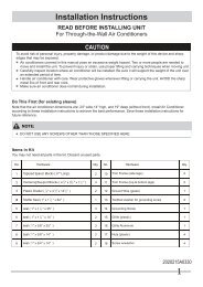
SERVICE PARTSModels 2830 & 2836Downdraft Blower Systems2451522658452347167711225511915627151 501174304646616 17 181049685060149614933845857645655463537670547582292822497
WARRANTYBROAN-NUTONE ONE YEAR LIMITED WARRANTY<strong>Broan</strong>-NuTone warrants to the original consumer purchaser of its products that suchproducts will be free from defects in materials or workmanship for a period of one yearfrom the date of original purchase. THERE ARE NO OTHER WARRANTIES,EXPRESS OR IMPLIED, INCLUDING, BUT NOT LIMITED TO, IMPLIED WARRAN-TIES OF MERCHANTABILITY OR FITNESS FOR A PARTICULAR PURPOSE.During this one-year period, <strong>Broan</strong>-NuTone will, at its option, repair or replace,without charge, any product or part which is found to be defective under normal useand service.THIS WARRANTY DOES NOT EXTEND TO FLUORESCENT LAMP STARTERSAND TUBES. This warranty does not cover (a) normal maintenance and service or(b) any products or parts which have been subject to misuse, negligence, accident,improper maintenance or repair (other than by <strong>Broan</strong>-NuTone), faulty installation orinstallation contrary to recommended installation instructions.The duration of any implied warranty is limited to the one-year period as specified forthe express warranty. Some states do not allow limitation on how long an impliedwarranty lasts, so the above limitation may not apply to you.BROAN-NUTONE’S OBLIGATION TO REPAIR OR REPLACE, AT BROAN-NUTONE’S OPTION, SHALL BE THE PURCHASER’S SOLE AND EXCLUSIVEREMEDY UNDER THIS WARRANTY. BROAN-NUTONE SHALL NOT BE LIABLEFOR INCIDENTAL, CONSEQUENTIAL OR SPECIAL DAMAGES ARISING OUTOF OR IN CONNECTION WITH PRODUCT USE OR PERFORMANCE. Somestates do not allow the exclusion or limitation of incidental or consequential damages,so the above limitation or exclusion may not apply to you.This warranty gives you specific legal rights, and you may also have other rights,which vary from state to state. This warranty supersedes all prior warranties.To qualify for warranty service, you must (a) notify the appropriate company at theaddress or phone number below (b) give the model number and part identificationand (c) describe the nature of any defect in the product or part. At the time ofrequesting warranty service, you must present evidence of the original purchasedate.<strong>Broan</strong>-NuTone LLC Hartford, Wisconsinwww.broan.com 800-558-1711 www.nutone.com 888-336-394899042138N