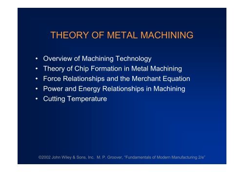
THEORY OF METAL MACHINING
THEORY OF METAL MACHINING
THEORY OF METAL MACHINING

You also want an ePaper? Increase the reach of your titles
YUMPU automatically turns print PDFs into web optimized ePapers that Google loves.
Why Machining is Important• Variety of work materials can be machined Most frequently applied to metals• Variety of part shapes and special geometryfeatures possible, such as: Screw threads Accurate round holes Very straight edges and surfaces• Good dimensional accuracy and surface finish©2002 John Wiley & Sons, Inc. M. P. Groover, “Fundamentals of Modern Manufacturing 2/e”
Disadvantages with Machining•Wasteful of materialChips generated in machining are wasted material,at least in the unit operation•Time consumingA machining operation generally takes more timeto shape a given part than alternative shapingprocesses, such as casting, powder metallurgy, orforming©2002 John Wiley & Sons, Inc. M. P. Groover, “Fundamentals of Modern Manufacturing 2/e”
Machining in the Manufacturing Sequence•Generally performed after other manufacturingprocesses, such as casting, forging, and bar drawingOther processes create the general shape of thestarting workpartMachining provides the final shape, dimensions,finish, and special geometric details that otherprocesses cannot create©2002 John Wiley & Sons, Inc. M. P. Groover, “Fundamentals of Modern Manufacturing 2/e”
Machining Operations•Most important machining operations:TurningDrillingMilling•Other machining operations:Shaping and planingBroachingSawing©2002 John Wiley & Sons, Inc. M. P. Groover, “Fundamentals of Modern Manufacturing 2/e”
TurningSingle point cutting tool removes material from arotating workpiece to form a cylindrical shapeFigure 21.3 (a) turning©2002 John Wiley & Sons, Inc. M. P. Groover, “Fundamentals of Modern Manufacturing 2/e”
DrillingUsed to create a round hole, usually by means of arotating tool (drill bit) that has two cutting edgesFigure 21.3 - The three mostcommon types of machiningprocess: (b) drilling©2002 John Wiley & Sons, Inc. M. P. Groover, “Fundamentals of Modern Manufacturing 2/e”
MillingRotating multiple-cutting-edge tool is moved slowlyrelative to work to generate plane or straight surface•Two forms: peripheral milling and face millingFigure 21.3 - (c) peripheral milling, and (d) face milling©2002 John Wiley & Sons, Inc. M. P. Groover, “Fundamentals of Modern Manufacturing 2/e”
Cutting Tool Classification1. Single-Point Tools One cutting edge Turning uses single point tools Point is usually rounded to form a nose radius2. Multiple Cutting Edge Tools More than one cutting edge Motion relative to work usually achieved byrotating Drilling and milling use rotating multiple cuttingedge tools.©2002 John Wiley & Sons, Inc. M. P. Groover, “Fundamentals of Modern Manufacturing 2/e”
Figure 21.4 - (a) A single-point tool showing rake face, flank, and toolpoint; and (b) a helical milling cutter, representative of tools withmultiple cutting edges©2002 John Wiley & Sons, Inc. M. P. Groover, “Fundamentals of Modern Manufacturing 2/e”
Cutting Conditions in Machining•The three dimensions of a machining process:Cutting speed v –primary motionFeed f –secondary motionDepth of cut d –penetration of tool below originalwork surface•For certain operations, material removal rate can befound asMRR = v f dwhere v = cutting speed; f = feed; d = depth of cut©2002 John Wiley & Sons, Inc. M. P. Groover, “Fundamentals of Modern Manufacturing 2/e”
Cutting Conditions for TurningFigure 21.5 - Cutting speed, feed, and depth of cut for a turningoperation©2002 John Wiley & Sons, Inc. M. P. Groover, “Fundamentals of Modern Manufacturing 2/e”
Roughing vs. Finishing in MachiningIn production, several roughing cuts are usually takenon the part, followed by one or two finishing cuts•Roughing - removes large amounts of material fromthe starting workpartCreates shape close to desired geometry, butleaves some material for finish cuttingHigh feeds and depths, low speeds•Finishing - completes part geometryAchieves final dimensions, tolerances, and finishLow feeds and depths, high cutting speeds©2002 John Wiley & Sons, Inc. M. P. Groover, “Fundamentals of Modern Manufacturing 2/e”
Machine ToolsA power-driven machine that performs a machiningoperation, including grinding•Functions in machining:Holds workpartPositions tool relative to workProvides power at speed, feed, and depth thathave been set•The term is also applied to machines that performmetal forming operations©2002 John Wiley & Sons, Inc. M. P. Groover, “Fundamentals of Modern Manufacturing 2/e”
Orthogonal Cutting ModelA simplified 2-D model of machining that describes themechanics of machining fairly accuratelyFigure 21.6 - Orthogonal cutting: (a) as a three-dimensional process©2002 John Wiley & Sons, Inc. M. P. Groover, “Fundamentals of Modern Manufacturing 2/e”
tr tChip Thickness Ratioocwhere r = chip thickness ratio; t o= thickness of thechip prior to chip formation; and t c= chip thicknessafter separation•Chip thickness after cut is always greater than before,so chip ratio is always less than 1.0©2002 John Wiley & Sons, Inc. M. P. Groover, “Fundamentals of Modern Manufacturing 2/e”
Determining Shear Plane Angle•Based on the geometric parameters of the orthogonalmodel, the shear plane angle can be determined as:costan r1 r sinwhere r = chip ratio, and = rake angle©2002 John Wiley & Sons, Inc. M. P. Groover, “Fundamentals of Modern Manufacturing 2/e”
Figure 21.7 - Shear strain during chip formation: (a) chip formationdepicted as a series of parallel plates sliding relative to each other,(b) one of the plates isolated to show shear strain, and (c) shearstrain triangle used to derive strain equation©2002 John Wiley & Sons, Inc. M. P. Groover, “Fundamentals of Modern Manufacturing 2/e”
Shear StrainShear strain in machining can be computed from thefollowing equation, based on the preceding parallelplate model:= tan(- ) + cot where = shear strain, = shear plane angle, and =rake angle of cutting tool©2002 John Wiley & Sons, Inc. M. P. Groover, “Fundamentals of Modern Manufacturing 2/e”
Figure 21.8 - More realistic view of chip formation, showing shearzone rather than shear plane. Also shown is the secondary shearzone resulting from tool-chip friction©2002 John Wiley & Sons, Inc. M. P. Groover, “Fundamentals of Modern Manufacturing 2/e”
Four Basic Types of Chip in Machining1. Discontinuous chip2. Continuous chip3. Continuous chip with Built-up Edge (BUE)4. Serrated chip©2002 John Wiley & Sons, Inc. M. P. Groover, “Fundamentals of Modern Manufacturing 2/e”
Segmented Chip•Brittle work materials(e.g., cast irons)•Low cutting speeds•Large feed and depth ofcut•High tool-chip frictionFigure 21.9 - Four types of chipformation in metal cutting:(a) segmented©2002 John Wiley & Sons, Inc. M. P. Groover, “Fundamentals of Modern Manufacturing 2/e”
Continuous Chip•Ductile work materials(e.g., low carbon steel)•High cutting speeds•Small feeds and depths•Sharp cutting edge onthe tool•Low tool-chip frictionFigure 21.9 - Four types of chipformation in metal cutting:(b) continuous©2002 John Wiley & Sons, Inc. M. P. Groover, “Fundamentals of Modern Manufacturing 2/e”
Continuous with BUE•Ductile materials•Low-to-medium cuttingspeeds•Tool-chip friction causesportions of chip to adhere torake face•BUE formation is cyclical; itforms, then breaks offFigure 21.9 - Four types of chipformation in metal cutting: (c)continuous with built-up edge©2002 John Wiley & Sons, Inc. M. P. Groover, “Fundamentals of Modern Manufacturing 2/e”
Serrated Chip•Semicontinuous - sawtoothappearance•Cyclical chip formationof alternating high shearstrain then low shearstrain•Most closely associatedwith difficult-to-machinemetals at high cuttingspeedsFigure 21.9 - Four types of chipformation in metal cutting: (d)serrated©2002 John Wiley & Sons, Inc. M. P. Groover, “Fundamentals of Modern Manufacturing 2/e”
Forces Acting on Chip•Friction force F and Normal force to friction N•Shear force F sand Normal force to shear F nFigure 21.10 -Forces in metalcutting: (a) forcesacting on the chipin orthogonalcutting©2002 John Wiley & Sons, Inc. M. P. Groover, “Fundamentals of Modern Manufacturing 2/e”
Resultant Forces•Vector addition of F and N = resultant R•Vector addition of F sand F n= resultant R'• Forces acting on the chip must be in balance:R' must be equal in magnitude to RR’must be opposite in direction to RR’must be collinear with R©2002 John Wiley & Sons, Inc. M. P. Groover, “Fundamentals of Modern Manufacturing 2/e”
Coefficient of FrictionCoefficient of friction between tool and chip:FNFriction angle related to coefficient of friction asfollows:tan©2002 John Wiley & Sons, Inc. M. P. Groover, “Fundamentals of Modern Manufacturing 2/e”
Shear StressShear stress acting along the shear plane:FS Awhere A s= area of the shear planeAs sstowsinShear stress = shear strength of work material duringcutting©2002 John Wiley & Sons, Inc. M. P. Groover, “Fundamentals of Modern Manufacturing 2/e”
Cutting Force and Thrust Force•Forces F, N, F s, and F ncannot be directly measured•Forces acting on the tool that can be measured:Cutting force F cand Thrust force F tFigure 21.10 - Forcesin metal cutting: (b)forces acting on thetool that can bemeasured©2002 John Wiley & Sons, Inc. M. P. Groover, “Fundamentals of Modern Manufacturing 2/e”
Forces in Metal Cutting•Equations can be derived to relate the forces thatcannot be measured to the forces that can bemeasured:F = F csin + F tcosN = F ccos- F tsinF s= F ccos- F tsinF n= F csin+ F tcos•Based on these calculated force, shear stress andcoefficient of friction can be determined©2002 John Wiley & Sons, Inc. M. P. Groover, “Fundamentals of Modern Manufacturing 2/e”
The Merchant Equation•Of all the possible angles at which shear deformationcould occur, the work material will select a shearplane angle which minimizes energy, given by 45 2 2•Derived by Eugene Merchant•Based on orthogonal cutting, but validity extends to3-D machining©2002 John Wiley & Sons, Inc. M. P. Groover, “Fundamentals of Modern Manufacturing 2/e”
What the Merchant Equation Tells Us45 2 2•To increase shear plane angleIncrease the rake angleReduce the friction angle (or coefficient of friction)©2002 John Wiley & Sons, Inc. M. P. Groover, “Fundamentals of Modern Manufacturing 2/e”
•Higher shear plane angle means smaller shear planewhich means lower shear force•Result: lower cutting forces, power, temperature, allof which mean easier machiningFigure 21.12 - Effect of shear plane angle: (a) higher with aresulting lower shear plane area; (b) smaller with a correspondinglarger shear plane area. Note that the rake angle is larger in (a), whichtends to increase shear angle according to the Merchant equation©2002 John Wiley & Sons, Inc. M. P. Groover, “Fundamentals of Modern Manufacturing 2/e”
Power and Energy Relationships•A machining operation requires powerThe power to perform machining can be computed from:P c= F cvwhere P c= cutting power; F c= cutting force; and v =cutting speed©2002 John Wiley & Sons, Inc. M. P. Groover, “Fundamentals of Modern Manufacturing 2/e”
Power and Energy RelationshipsIn U.S. customary units, power is traditional expressedas horsepower (dividing ft-lb/min by 33,000)HPc Fcv33,000where HP c= cutting horsepower, hp©2002 John Wiley & Sons, Inc. M. P. Groover, “Fundamentals of Modern Manufacturing 2/e”
Power and Energy RelationshipsGross power to operate the machine tool P gor HP gisgiven byPg PEcorHPg HPEwhere E = mechanical efficiency of machine tool•Typical E for machine tools = 90%c©2002 John Wiley & Sons, Inc. M. P. Groover, “Fundamentals of Modern Manufacturing 2/e”
Unit Power in Machining•Useful to convert power into power per unit volumerate of metal cut•Called the unit power, P uor unit horsepower, HP uPu PcMRRorHPu HPcMRRwhere MRR = material removal rate©2002 John Wiley & Sons, Inc. M. P. Groover, “Fundamentals of Modern Manufacturing 2/e”
Specific Energy in MachiningUnit power is also known as the specific energy UUPuPcMRRFvtcovwFct woUnits for specific energy are typically N-m/mm 3 or J/mm 3(in-lb/in 3 )©2002 John Wiley & Sons, Inc. M. P. Groover, “Fundamentals of Modern Manufacturing 2/e”
Cutting Temperature•Approximately 98% of the energy in machining isconverted into heat•This can cause temperatures to be very high at thetool-chip•The remaining energy (about 2%) is retained aselastic energy in the chip©2002 John Wiley & Sons, Inc. M. P. Groover, “Fundamentals of Modern Manufacturing 2/e”
Cutting Temperature•Several analytical methods to calculate cuttingtemperature•Method by N. Cook derived from dimensionalanalysis using experimental data for various workmaterialsT0.4Uvt CK0.333where T = temperature rise at tool-chip interface; U =specific energy; v = cutting speed; t o= chip thicknessbefore cut; C = volumetric specific heat of workmaterial; K = thermal diffusivity of the work materialo©2002 John Wiley & Sons, Inc. M. P. Groover, “Fundamentals of Modern Manufacturing 2/e”
Cutting Temperature•Experimental methods can be used to measuretemperatures in machining•Most frequently used technique is the tool-chipthermocouple•Using this method, K. Trigger determined thespeed-temperature relationship to be of the form:T = K v mwhere T = measured tool-chip interface temperature©2002 John Wiley & Sons, Inc. M. P. Groover, “Fundamentals of Modern Manufacturing 2/e”