Editing Controller Setting - Panasonic PASS
Editing Controller Setting - Panasonic PASS
Editing Controller Setting - Panasonic PASS
- No tags were found...
Create successful ePaper yourself
Turn your PDF publications into a flip-book with our unique Google optimized e-Paper software.
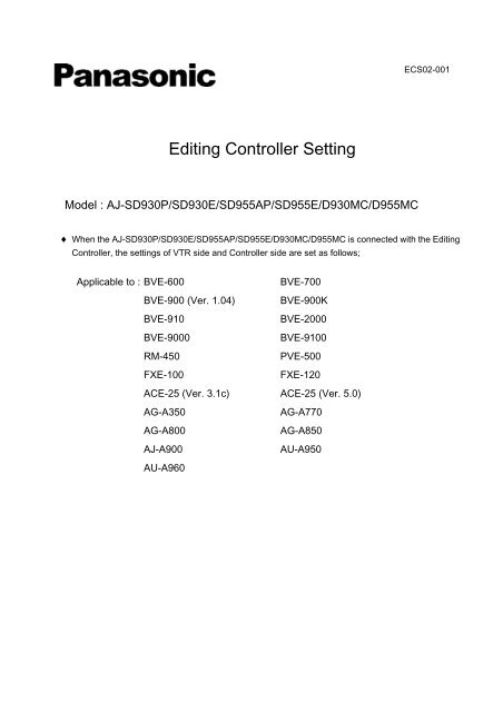
Note >∗ SETUP Menu No. 313 : AFTER CUE-UP is set to STOP (Default <strong>Setting</strong>). (at BVE-800, editing is executed whenthe VTR goes to STOP mode after CUE-UP completion.)∗ In case of no input reference signal to the VTR, SETUP Menu No. 104 : REF ALARM is set to OFF. (Control fromthe BVE-800 cannot be available)BVE-900 (Ver. 1.04) <strong>Setting</strong>1. Both Recorder and Player VTR CONSTANT are set as follows.CONSTANT 1 CONSTANT 2DATADATA1 2 3 4 5 6 7 8 1 2 3 4 5 6 7AJ-SD930P/SD955AP F0 33 00 5A 08 08 07 0F 0C 06 FB 00 81 3D 20AJ-D930MC/D955MC/SD930E/SD955EF1 33 00 4B 08 08 07 0F 0C 06 FB 00 83 3B 20∗ More than version 1.06 of BVE-900 is set to the same as BVE-910 setting. (CUE UP function by the CUE-UPWITH DATA command can be available.)BVE-900K, BVE-910 <strong>Setting</strong>1. Both Recorder and Player VTR CONSTANT are set as follows.CONSTANT 1 CONSTANT 2DATADATA1 2 3 4 5 6 7 8 1 2 3 4 5 6 7AJ-SD930P/SD955AP F0 33 00 5A 08 08 03 8A 0C 06 FB 00 81 3D FFAJ-D930MC/D955MC/SD930E/SD955EF1 33 00 4B 08 08 03 8A 0C 06 FB 00 83 3B FFIn case of executing the editing with PREROLL TIME = 3sec :CONSTANT 2 DATA-2 (Start Delay) is changed from above setting every Recorder and Player.In case of setting to Recorder side : CONSTANT 2 DATA-2 = 00In case of setting to Player side : CONSTANT 2 DATA-2 = 05BVE-2000 <strong>Setting</strong>1. Both Recorder and Player VTR CONSTANT are set as follows.DATA01 02 03 04 05 06 07 08 09 10 11 12 13 14 15AJ-SD930P/SD955AP F0 33 00 5A 08 08 03 8A 0C 06 FB 00 81 3D FFAJ-D930MC/D955MC/SD930E/SD955EF1 33 00 4B 08 08 03 8A 0C 06 FB 00 83 3B FFIn case of executing the editing with PREROLL TIME = 3sec :DATA-10 (Start Delay) is changed from above setting every Recorder and Player.In case of setting to Recorder side : DATA-10 = 00In case of setting to Player side : DATA-10 = 06BVE-9000/9100 <strong>Setting</strong>1. Both Recorder and Player VTR CONSTANT are set as follows.CONSTANT 1 CONSTANT 2DATADATA1 2 3 4 5 6 7 8 1 2 3 4 5 6 7 8AJ-SD930P/SD955AP F0 33 00 5A 08 08 03 8A 0C 06 FB 00 81 3D FF 5AAJ-D930MC/D955MC/SD930E/SD955EF1 33 00 4B 08 08 03 8A 0C 06 FB 00 83 3B FF 4BPage 3/7ECS02-001
In case of executing the editing with PREROLL TIME = 3sec :CONSTANT 2 DATA-2 (Start Delay) is changed from above setting every Recorder and Player.In case of setting to Recorder side : CONSTANT 2 DATA-2 = 00In case of setting to Player side : CONSTANT 2 DATA-2 = 06RM-450 <strong>Setting</strong> (same setting as AJ-D750 etc.)1. SYSTEM RESET switch is set to as follows.Left SideRight Side7 5 4 3 2 1 0 7 6 5 4 3 2 1 0OFF ON OFF OFF OFF OFF OFF OFF OFF ON OFF ON ON OFFNo. 7 of Right side : OFF = NTSC, ON = PAL2. SETUP Menu at the VTR side is set as follows.323 : JOG FWD MAX = +4.13. After selecting the Edit mode at RM-450, insert the recorded tape to both Player and Recorder sides. Thenpress the LEARN button.PVE-500 <strong>Setting</strong> (same setting as AJ-D750 etc.)1. SETUP-11 : ED DELAY (Edit Delay) at PVE-500 side is set to 6F (6 frame).1). Press the SETUP (ENTRY + EDIT) button.2). Rotate the Search Dial of Player side, then display ”SETUP-11”.3). Rotate the Search Dial of Recorder side, then set to ”6F”.4). Press the STORE (ENTRY + REC) button.5). Press the SETUP (ENTRY + EDIT) button again, then close the SETUP mode.2. After selecting the Edit mode at PVE-500, insert the recorded tape to both Player and Recorder sides. Thenpress the LEARN button.FXE-100 <strong>Setting</strong> (same setting as AJ-D750 etc.)1. VTR Device codes are set as follows.In case of setting to Recorder side :SETUP Menu No. 403 of FXE-100 is set to “ENABLE”, then set the BYTE of VTR as follows.AJ-SD930P/SD955AP/D930MC/D955MC/SD930E/SD955EBYTE01 02 03 04 05 06 07 08 09 10 11 12 13 14 15FF FF 00 5A 08 08 03 84 0A 08 FB 00 81 2F FFIn case of setting to Player side :SETUP Menu No. 401 or 402 of FXE-100 is set to “DISABLE”. (As the user setting code is not available, built-incode is available.)FXE-120 <strong>Setting</strong> (same setting as AJ-D750 etc.)1. VTR Device codes are set as follows.In case of setting to Recorder side :SETUP Menu No. 303 of FXE-120 is set to “ENABLE”, then set the BYTE of VTR as follows.BYTE01 02 03 04 05 06 07 08 09 10 11 12 13 14 15AJ-SD930P/SD955AP/D930MC/D955MC FF FF 00 5A 08 08 03 84 0A 08 FB 00 81 2F FF/SD930E/SD955EIn case of setting to Player side :SETUP Menu No. 301 or 302 of FXE-120 is set to “DISABLE”. (As the user setting value becomes invalid,internal value is used.)Page 4/7ECS02-001
ACE-25 (Ver. 3.1c) <strong>Setting</strong> (same setting as AJ-D750 etc.)1. Press the keys as follows ; [SYS INIT] → [HARDWARE CONFIG] → [SONY PROTOCOL], so, set it as beingCVR-75.2. Press the keys as follows ; [SYS INIT] → [SYSTEM OPTION]. Then, set the ENTRY OFFSET in the EDITOPTIONS to -3 Frames.3. SETUP Menu on the VTR side is set as follows;102 : FF.REW MAX = X32202 : ID SEL = OTHER316 : VAR STEP = FINE317 : VAR FWD MAX = +4.1ACE-25 (Ver. 5.0) <strong>Setting</strong> (same setting as AJ-D750 etc.)1. SETUP Menu on the VTR side is set as follows;202 : ID SEL = DVCPRO504 : REGEN MODE = ON2. Parameter of ACE-25 is set as follows;Menu Ampex Explanations VTRmin_id minimum machine id 0xF033max_id minimum machine id 0xF033name transport name DVCPRObDevFamily Device Family Code:0 : type C 1 : Betacam 2 : Digital 3 : Umatic 4 : M2 5 : JVC16 : audio 7 : UnkonwnfCanTTLoad 1 if transport can load a tape timer, 0 otherwise 1fColorFramer 1 if transport has a color framer, 0 otherwise 1fHeadSelect 1 if transport needs head selects, 0 otherwise 0fMifBased 1 if transport is Mif Based, 0 otherwise 0fSmartSearch 1 if transport cues intelligently, 0 otherwise 1fTwoByteSpeed 1 if transport can take a two byte speed, 0 otherwise 1bDelayVideo Video head delay 14bDelayAudio Audio head delay 14bInitialVideo Initial head delay 14bJogShift Jog Knob shift value 7bSyncMin Limit on sync variation 2bTimeoutSearch Search timeout in seconds 2bMaxMessages Max Messages for Sony Copy 2AG-A350 <strong>Setting</strong> (same setting as AJ-D750 etc.)1. DIP SW is set as follows.SW1SW21 2 3 4 5 6 1 2 3 4 5 6AJ-SD930P/SD955AP ON OFF ON OFF ON OFF ONAJ-D930MC/D955MC/SD930E/SD955EON OFF ON OFF ON OFF OFFSW1-1 : CTL Counter Display OFF = ± 12H ON= 24HSW1-2 : Counter Mode at Player side OFF = TC ON= CTLSW1-3 : Counter Mode at Recorder side OFF = TC ON= CTLSW1-5 : Selection of Synchronizationand Color Framing OFF, OFF = No SynchronizationSW1-6 : ON, OFF = 2F, SynchronizationOFF, ON = 4F, SynchronizationON, ON = <strong>Setting</strong> at VTR side, SynchronizationPage 5/7ECS02-001
AG-A770 <strong>Setting</strong> (same setting as AJ-D750 etc.)1. SW1, SW2 on the Panel side is set as follows.SW1SW21 2 3 4 5 6 7 8 1 2 3 4 5 6 7 8AJ-SD930P/SD955AP/D930MC/D955MC/SD930E/SD955EONON(Blank frame in the table is OFF)2. SW1 (SW501), SW2 (SW502) on the I/F Unit side is set as follows.SW1 (SW501)SW2 (SW502)1 2 3 4 5 6 7 8 1 2 3 4 5 6 7 8AJ-SD930P/SD955AP ON ONAJ-D930MC/D955MC/SD930E/SD955EON ON ONAG-A800 <strong>Setting</strong> (same setting as AJ-D750 etc.)1. SW1, SW2 on the Panel side is set as follows.AJ-SD930P/SD955AP/D930MC/D955MC/SD930E/SD955E(Blank frame in the table is OFF)SW1SW21 2 3 4 5 6 7 8 1 2 3 4 5 6 7 8ON OFF OFF OFF OFF ON ON ON ON OFF ON OFF ONSW1-1 : Buzzer at error operation OFF = Not go on ON= Go onSW1-2 : Direct Search OFF = Not available ON= AvailableSW2-2 : Switching Timing of GPI3 OFF = KEY Output Point ON= AUDIO Edit Point2. SW1 (SW501), SW2 (SW502) on the I/F Unit side is set as follows.SW1 (SW501)SW2 (SW502)1 2 3 4 5 6 7 8 1 2 3 4 5 6 7 8AJ-SD930P/SD955AP OFF ON ON OFF ONAJ-D930MC/D955MC/SD930E/SD955EON ON ON OFF ON(Blank frame in the table is not changed)AG-A850 <strong>Setting</strong>1. 01 : DEVICE TYPE of SETUP-12 : VTR CONSTANT at AG-A850 side is set to “FF FF” (Default).2. SETUP Menu No. 202 : ID SEL at the VTR side is set to “DVCPRO” (Default).In case of setting the PREROLL TIME to 3sec, the following SETUP Menu items in the SETUP-12 VTRCONSTANT at AG-A850 side are changed from the default setting.01 : DEVICE TYPE = FF FE02 : PREROLL TIME = 03:0007 : A SYNC DELAY- = 0315 : CUE-UP CHECK 2 = STSAJ-A900 <strong>Setting</strong>1. 1 : MODE of SETUP : VTR CONSTANT at AJ-A900 side is set to “AUTO” (Default).2. SETUP Menu No. 202 : ID SEL at the VTR side is set to “DVCPRO” (Default).In case of setting the PREROLL TIME to 3sec, the following SETUP Menu items in the SETUP VTR CONSTANTat AJ-A900 side are changed from the default setting.1 : MODE = PARAMETER ENABLE3 : PRESET PREROLL TIME = 03:009 : AFTER SYNC DELAY- = 03Page 6/7ECS02-001
AU-A950/A960 <strong>Setting</strong> (same setting as AJ-D750 etc.)1. SETUP Menu No. 202 : ID SEL at the VTR side is set to “DVCPRO” (Default).2. Both Recorder and Player VTR CONSTANT are set as follows.In case of AU-A950 (more than Ver. 2.0-2077) and AU-A960 (more than Ver. 2.1-2126) :AJ-SD930P/SD955AP/D930MC/D955MC/SD930E/SD955ECONSTANT 1 CONSTANT 2DATADATA1 2 3 4 5 6 7 8 1 2 3 4 5 6 7FF FF FF FF 06 06 01 00 03 06 FF 03 83 02 FF3. AUDIO CHANNEL ASSIGN of AU-A950 and A960 is set as follows.ANALOG A1 (CUE) = CUE KEY DIGITAL A1 = A1 KEYANALOG A2 (CUE) = CUE KEY DIGITAL A2 = A2 KEYANALOG A3 (TC) = TC KEY DIGITAL A3 = A3 KEYANALOG A4 = A4 KEY DIGITAL A4 = A4 KEYPage 7/7ECS02-001


