

FT Switch Family - Literature - FT-1 Configurator
FT Switch Family - Literature - FT-1 Configurator
FT Switch Family - Literature - FT-1 Configurator

Create successful ePaper yourself
Turn your PDF publications into a flip-book with our unique Google optimized e-Paper software.
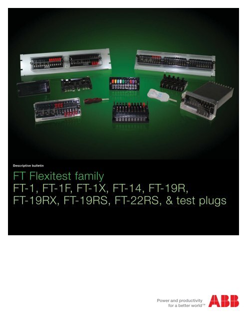
Descriptive bulletin<br />
<strong>FT</strong> Flexitest family<br />
<strong>FT</strong>-1, <strong>FT</strong>-1F, <strong>FT</strong>-1X, <strong>FT</strong>-14, <strong>FT</strong>-19R,<br />
<strong>FT</strong>-19RX, <strong>FT</strong>-19RS, <strong>FT</strong>-22RS, & test plugs
Index<br />
1. Application .....................................................................3<br />
2. The most complete family of test switches ...................4<br />
2.1. <strong>FT</strong>-1. ............................................................................4<br />
2.2. <strong>FT</strong>-1F ...........................................................................4<br />
2.3. <strong>FT</strong>-1X. ..........................................................................4<br />
2.4. <strong>FT</strong>-14. ..........................................................................4<br />
2.5. The <strong>FT</strong>-19R and <strong>FT</strong>-19RX ............................................4<br />
2.6. The <strong>FT</strong>-19RS ..............................................................5<br />
2.7. <strong>FT</strong>-22RS .....................................................................5<br />
3. Advantages ....................................................................6<br />
3.1. Safe and convenient ...................................................6<br />
3.2. Fast and reliable .........................................................6<br />
3.3. Maximum flexibility .....................................................6<br />
3.4. Security .......................................................................6<br />
3.5. Quality .........................................................................6<br />
3.6. Technical and application engineering support ..........6<br />
4. Specifications ................................................................7<br />
4.1. Certifications ..............................................................7<br />
4.2. Ratings ........................................................................7<br />
4.3. Mounting .....................................................................7<br />
4.4. Construction ...............................................................8<br />
4.5. Cover .........................................................................8<br />
4.6. Poles ..........................................................................9<br />
4.6.1. Potential poles ........................................................9<br />
4.6.2. Current poles ...........................................................9<br />
4.7. <strong>Switch</strong> handles ...........................................................11<br />
4.8. Terminal connections ..................................................11<br />
4.9. <strong>Switch</strong> arrangement ....................................................12<br />
2 <strong>FT</strong> Flexitest family | Descriptive bulletin<br />
5. Test plugs ......................................................................13<br />
5.1. In-service series test plug ...........................................13<br />
5.2. Individual current circuit test plug ..............................13<br />
5.3. Individual current circuit test plug with open CT<br />
protection ...................................................................13<br />
5.4. Separate source test plug ...........................................14<br />
5.5. Flexitest test kit ..........................................................14<br />
6. <strong>FT</strong> Flexitest switches ordering information ....................17<br />
6.1. <strong>FT</strong>-1, <strong>FT</strong>-1F and <strong>FT</strong>-1X switches ..................................18<br />
6.1.1. Terminal connections ...............................................18<br />
6.1.2. Cover .......................................................................18<br />
6.1.3. Depth .......................................................................18<br />
6.1.4. Front connected .......................................................18<br />
6.2. <strong>FT</strong>-14. ..........................................................................18<br />
6.2.1. Terminal connections ...............................................18<br />
6.2.2. Cover .......................................................................18<br />
6.3 <strong>FT</strong>-19 and <strong>FT</strong>-22 test switch assemblies ......................19<br />
6.3.1 Terminal connections ................................................19<br />
6.3.2 Panel height ..............................................................19<br />
6.3.3 Panel color & material ...............................................19<br />
6.3.4 Flexitest switch code numbers (positions<br />
A, B, and C) ...............................................................19<br />
6.3.5 <strong>Switch</strong> replacement ..................................................19<br />
6.3.6 Cover ........................................................................19<br />
6.3.7 Additional features ....................................................19<br />
7. Test plugs & accessories - ordering information ..........27<br />
8. Warranty ........................................................................29
1. Application<br />
ABB Flexitest switches, types <strong>FT</strong>-1 (10 pole, rear connected),<br />
<strong>FT</strong>-1F (10 pole, front connected), <strong>FT</strong>-1X (10 pole, extended<br />
terminals, rear connected), <strong>FT</strong>-14 (14 pole, rear connected), and<br />
associated Test Plugs, provide a safe, simple, fast and reliable<br />
method to isolate, test, and service installed equipment without<br />
disturbing the system.<br />
<strong>FT</strong>-19R, <strong>FT</strong>-19RX, <strong>FT</strong>-19RS, and <strong>FT</strong>-22RS Flexitest switch<br />
assemblies for rack and switchboard mounting also permit convenient<br />
isolation of switchboard relays, meters, and instruments<br />
allowing quick and easy multi-circuit testing by any conventional<br />
test method. These assemblies utilize <strong>FT</strong>-1 and/or <strong>FT</strong>-14<br />
switches, depending on customer’s requirements.<br />
Descriptive bulletin | <strong>FT</strong> Flexitest family 3
2. The most complete family of test switches<br />
2.1. <strong>FT</strong>-1 Standard 10 pole, rear connected test switch.<br />
2.2. <strong>FT</strong>-1F Surface mount switch allows the user to make the<br />
same connections as with <strong>FT</strong>-1 but on the front of the switch.<br />
2.3. <strong>FT</strong>-1X Extended length test switch brings the rear terminal<br />
connections to the same depth as most panel mounted protective<br />
relays and equipment for easier and faster access to wiring<br />
points. Extended 8 inches or 10 inches depth is available.<br />
2.4. <strong>FT</strong>-14 Provides the same features and reliability as <strong>FT</strong>-1 but<br />
with a maximum of 14 individual poles. Although supplying 40%<br />
more capacity than the <strong>FT</strong>-1, the <strong>FT</strong>-14 only requires 18% more<br />
space.<br />
1 <strong>FT</strong>-1 | 2 <strong>FT</strong>-1F | 3 <strong>FT</strong>-1X | 4 <strong>FT</strong>-14 | 5 <strong>FT</strong>-19R 2RU with Full Length Clear Cover<br />
1<br />
3 4 5<br />
4 <strong>FT</strong> Flexitest family | Descriptive bulletin<br />
2.5. The <strong>FT</strong>-19R and <strong>FT</strong>-19RX assemblies accommodate up to<br />
three <strong>FT</strong>-1 switches mounted on a 19” wide, and two-rack unit<br />
(2RU), three-rack unit (3RU), or four-rack unit (4RU) high panel<br />
suitable for rack or switchboard mounting. These assemblies<br />
can be ordered with a full-length clear cover (standard), or optional<br />
individual clear covers for each switch.<br />
The <strong>FT</strong>-19RX extends the rear terminals of the <strong>FT</strong>-1 switches to<br />
the same depth as most 19” rack mounted equipment thereby<br />
providing improved access to the rear terminals. <strong>FT</strong>-19RX tworack<br />
unit assemblies (2RU) allow the user to mount protective<br />
relays or other equipment in the racks directly above and below<br />
the <strong>FT</strong>-19RX, optimizing the space in the rack and reducing the<br />
amount of wire required.<br />
2
2.6. <strong>FT</strong>-19RS assemblies consist of up to two <strong>FT</strong>-1 switches,<br />
two <strong>FT</strong>-14 switches, or the combination of one <strong>FT</strong>-1 and one<br />
<strong>FT</strong>-14 switch mounted on a 19” wide, and two-rack unit (2RU),<br />
three-rack unit (3RU), or four-rack unit (4RU) high panel suitable<br />
for rack or switchboard mounting. Any combination of <strong>FT</strong>-1 or<br />
<strong>FT</strong>-14 switches styles may be selected with individual black or<br />
clear covers. Non-ABB equipment is not included with the assembly<br />
(see circle in picture 9 below).<br />
2.7. <strong>FT</strong>-22RS assemblies consists of up to three <strong>FT</strong>-1 or two <strong>FT</strong>-<br />
14 switches mounted on a 22” wide, two-rack unit (2RU), threerack<br />
unit (3RU), or four-rack unit (4RU) high mounting panel<br />
suitable for rack or switchboard mounting. Any combination of<br />
<strong>FT</strong>-1 or <strong>FT</strong>-14 switches styles may be selected with individual<br />
black or clear covers.<br />
6<br />
9<br />
7<br />
Mounting panels for these assemblies may be of steel or aluminum.<br />
Steel panels are commonly available in gray, beige and<br />
black; although panel color or finish, as well as panel height,<br />
can be customized to meet the user’s necessities. The three<br />
rack unit (3RU) assembly also allows switches to be positioned<br />
off-center, in either low or high upper mounting positions in the<br />
rack panel, allowing room for special label requirements, as<br />
shown on page 5, figure 7.<br />
6 <strong>FT</strong>-19 3RU lockable version | 7 <strong>FT</strong>-19R 3RU with Full Length Clear Cover. <strong>Switch</strong>es mounted in the lower position, with special customer labels | 8 <strong>FT</strong>-19RX<br />
3RU with Full Length Clear Cover | 9 <strong>FT</strong>-19RS | 10 <strong>FT</strong>-22RS<br />
10<br />
8<br />
Descriptive bulletin | <strong>FT</strong> Flexitest family 5
3. Advantages<br />
Flexitest test switches provide a safe, reliable, and cost-effective<br />
means to wire the output of relays, meters, and other associated<br />
equipment to external devices for in-service testing.<br />
3.1.Safe and convenient<br />
All measurements and tests can be performed at the front of<br />
the switchboard, without taking any devices out of service, and<br />
without the need to access wiring at the rear of the devices.<br />
Flexitest switches and test plugs have all the features necessary<br />
for applications involving the safe measurement and isolation of<br />
individual currents, voltages, and digital I/O signals to facilitate<br />
testing of substation instrumentation and protection devices.<br />
The make-before-break current shorting feature allows test<br />
personnel to quickly and safely isolate equipment from current<br />
transformer (CT) circuits.<br />
Voltage measurements can also be made directly on Flexitest<br />
switches, without disturbing existing connections. There is a<br />
test clip located on the top of each pole that allows connection<br />
with standard spring clip test leads.<br />
3.2. Fast and reliable<br />
When test plugs are used, any number of circuits may be tested<br />
in rapid succession. One plug properly connected can test all<br />
instruments or meters of a particular type.<br />
6 <strong>FT</strong> Flexitest family | Descriptive bulletin<br />
3.3. Maximum flexibility<br />
Test switches can be assembled in a variety of different arrangements,<br />
to match customer requirements. To build new or view<br />
existing Flexitest <strong>Switch</strong>es and <strong>FT</strong>-19R panels, please visit our<br />
interactive <strong>FT</strong>-1 <strong>Configurator</strong> website at http://ft1switch.com<br />
(see page 15).<br />
3.4. Security<br />
With the cover in place, a meter seal can be placed through<br />
either of the cover studs of any Flexitest switch to prevent unauthorized<br />
access to the switch. As an additional feature, a clear<br />
cover is available that can also be installed with the switchblades<br />
in the fully open or closed positions. In addition, a barrier<br />
has been incorporated into the cover to prevent knife switches<br />
from being left partially open. Optional padlocking provisions are<br />
available for most covers allowing access to authorized personnel<br />
only.<br />
3.5. Quality<br />
With over 50 years of field proven applications, ABB is the<br />
test switch manufacturer with the highest quality and largest<br />
installed base in North America. ABB’s Flexitest test switches<br />
have been an industry standard for years.<br />
3.6.Technical and application engineering support<br />
Available 24/7 at +1 800 HELP 365, option 8; or +1 440 585<br />
7804.
4. Specifications<br />
4.1. Certifications<br />
All Flexitest <strong>Switch</strong>es meet or exceed all requirements of ANSI/<br />
IEEE Standard C37.90. Class 1E switches meet IEEE C37.98,<br />
C37.105, 323-1983 and 344-1987 Standards.<br />
UL and CUL file number E103204, CSA, and 1E certification are<br />
available for most test switches. Contact your ABB representative<br />
for more details.<br />
4.2. Ratings<br />
All Flexitest switches are rated at 600 Volts AC and 30 Amps.<br />
4.3. Mounting<br />
The <strong>FT</strong>-1, <strong>FT</strong>-14, and <strong>FT</strong>-1X switches are designed for semiflush<br />
mounting on the front of switchboard panels, facilitating<br />
inspection and accessibility. The <strong>FT</strong>-1F is designed for surface<br />
mounting and can also be mounted on a unistrut with the use<br />
of a unistrut adapter plate. Refer to figures 7 to 9 beginning on<br />
page 30 for the specific outline and drilling plan information of<br />
each switch.<br />
The <strong>FT</strong>-19R, <strong>FT</strong>-19RX, and <strong>FT</strong>-19RS are designed for mounting<br />
on 19-inch rack structures or conventional panels. The <strong>FT</strong>-22RS<br />
are designed for mounting on 22-inch rack<br />
structures.<br />
Connections, dimensions and layout are shown on pages 30-<br />
37.<br />
Approximate shipping weight and dimensions<br />
Device type Net<br />
Shipping<br />
Shipping container<br />
lbs (kg)<br />
lbs (kg)<br />
L x W x H in (mm)<br />
<strong>FT</strong>-1 and <strong>FT</strong>-1F 1.75 (0.79) 3 (1.4) 4 (100) x 7 (177) x 5 (126)<br />
<strong>FT</strong>-1X 2.7 (1.25) 3.75 (1.7) 4 (100) x 12 (300) x 7 (177)<br />
<strong>FT</strong>-14 2.5 (1.5) 3.25 (1.5) 4 (100) x 9 (225) x 5 (126)<br />
<strong>FT</strong>-19R 7.0 (3.18) 12 (6) 10 (254) x 21 (534) x 10 (254)<br />
<strong>FT</strong>-19RX 9.0 (4.08) 17 (8) 10 (254) x 21 (534) x 16 (407)<br />
<strong>FT</strong>-19RS 7.0 (3.18) 12 (6) 10 (254) x 21 (534) x 10 (254)<br />
<strong>FT</strong>-22RS 7.0 (3.18) 12 (6) 10 (254) x 24 (610) x 10 (254)<br />
Separate Source Test Plug<br />
1.5 (0.68) 3 (1.4) 10 (253) x 7 (177) x 5 (126)<br />
(10 position)<br />
For up to 4 pieces<br />
In-Service Series Test Plug<br />
1.5 (0.68) 3 (1.4) 10 (253) x 7 (177) x 5 (126)<br />
(10 position)<br />
For up to 4 pieces<br />
Individual Current Circuit Test Plug 0.1 (0.045) 1 (0.45) 10 (253) x 7 (177) x 5 (126)<br />
For up to 30 pieces<br />
Descriptive bulletin | <strong>FT</strong> Flexitest family 7
4.4. Construction<br />
The base of all Flexitest switches is made of a high grade<br />
molded thermo-plastic which provides a tough, insulated<br />
enclosure. Barriers are molded into the base (front and rear) to<br />
separate the switch units from one another. The barriers provide<br />
insulation between poles, and also ample wiring space between<br />
terminals. The terminals of the <strong>FT</strong>-1X are extended either 8 or<br />
10 inches beyond the switch blades located on the front of the<br />
switch. The back of the terminals is marked with a white raised<br />
3-D numbering, which allows easier identification of poles and<br />
helps prevent inadvertent upside down installation.<br />
4.5. Cover<br />
All Flexitest switch covers provide a tough insulated enclosure<br />
for the switch and are made from a durable thermoplastic material.<br />
Covers are fastened to the switches with thumbnuts on<br />
either end that can be loosened and tightened by hand, or with<br />
a 1/4” nut driver. This is the same size nut driver used on the<br />
hex head terminal screws of all Flexitest <strong>Switch</strong>es. All covers<br />
have the provision to accept meter seals.<br />
All switches may be purchased with a black opaque cover or<br />
a clear cover. The clear cover offers the user the unique option<br />
of intentionally leaving switch handles in the open position with<br />
the cover in place, maintaining the provision for a meter seal.<br />
This allows the user to service electrical equipment while still<br />
complying with OSHA tag and lockout procedures.<br />
Lockable covers (in black or clear) are also available upon<br />
request.<br />
Any cover can be ordered separately to retrofit any existing<br />
switch, maintaining the same ease of use and accessibility. See<br />
ordering information on page 28.<br />
<strong>FT</strong> Cover selection samples (a) Black; (b) Clear; (c) Lockable<br />
8 <strong>FT</strong> Flexitest family | Descriptive bulletin<br />
Figure 1. <strong>FT</strong> switch terminal numbering, rear view.
4.6. Poles<br />
<strong>FT</strong>-1, <strong>FT</strong>-1F and <strong>FT</strong>-1X switches are available in combinations<br />
of 1 to a maximum of 10 individual poles or switch units. <strong>FT</strong>-14<br />
switches are available in combinations of 1 to a maximum of 14<br />
poles or switch units. Each pole is identified by a letter (A to J or<br />
A to N) visible along the top of the base from left to right (front<br />
view).<br />
Individual pole designations are used to identify each pole according<br />
to its type or function. In order to develop a complete<br />
<strong>Switch</strong> Arrangement, pole designations should be listed sequentially<br />
from left to right to account for every pole position on<br />
the switch. Unused poles are identified by the letter X.<br />
Each individual pole is of a knife blade type. There are two different<br />
types of poles, Potential and Current.<br />
For quick, easy, user friendly configuration of flexitest switches,<br />
please visit www.ft1switch.com.<br />
4.6.1. Potential poles<br />
Potential poles (P) are configured as single, non-shorting knife<br />
blades for use in potential, trip, or control circuits. P designates<br />
a potential, trip, or control circuit with a black handle. Potential<br />
poles with other color handles are available by replacing the “P”<br />
with the appropriate designation per chart on page 10.<br />
Figure 2. Blade assembly of 2 position pole “C-C”<br />
Current test jack<br />
Non-shorting blade<br />
Each potential pole can also be described with 2 characters<br />
(P1 to P9). P indicates Potential and the second character is a<br />
numeric color code for the switch handle.<br />
4.6.2. Current poles<br />
Current poles are typically configured in sets of two (C-C), for<br />
use with current circuits, and consist of a current test jack, a<br />
shorting spring, a shorting blade, and a non-shorting blade (see<br />
Figure 2) The positions of the short circuit springs are always<br />
visible from the front of the switch.<br />
C designates a single Current circuit, non-shorting pole, with a<br />
current test jack and a black handle. Current poles with other<br />
color handles are available by replacing the “C” with the appropriate<br />
designation per chart on page 10.<br />
Each current pole can also be described with 2 characters (C1<br />
to C9). C indicates Current and the second character is a numeric<br />
color code for the switch handle.<br />
Current poles typically span more than one pole position. Pole<br />
designations C-C, C-C-C, C-C-C-C and C-C-C-C-C indicate<br />
current shorting poles (make-before-break) with black handles.<br />
Note that any color handle may be selected for any pole position<br />
by using the appropriate pole designation, ex: 5-R or C-9-7<br />
(alternately C5-C2 or C1-C9-C7).<br />
Note: Before shorting blade disengages from<br />
jaw, bottom cam on blade is making contact<br />
with shorting spring<br />
Shorting blade<br />
Shorting spring<br />
Descriptive bulletin | <strong>FT</strong> Flexitest family 9
Visit www.ft1switch.com to build any complete <strong>FT</strong> switch arrangement, select options, view schematic details and get style number<br />
information.<br />
Pole type Potential pole<br />
designation<br />
Potential<br />
Current<br />
Current<br />
Shorting †<br />
Handle<br />
color<br />
P P1 Black<br />
T P2 Red<br />
H P3 Brown<br />
V P4 Purple<br />
G P5 Green<br />
Y P6 Yellow<br />
Z P7 Blue<br />
W P8 White<br />
O P9 Orange<br />
10 <strong>FT</strong> Flexitest family | Descriptive bulletin<br />
Description & schematic symbol<br />
Potential, non-shorting blade<br />
L L1 Black †† Potential, shorting blade<br />
C C1 Black<br />
R C2 Red<br />
3 C3 Brown<br />
4 C4 Purple<br />
5 C5 Green<br />
6 C6 Yellow<br />
7 C7 Blue<br />
8 C8 White<br />
9 C9 Orange<br />
Current, non-shorting, with test jack and<br />
blade<br />
D D0 N/A Current test jack, no switch blade<br />
C-C C1-C1<br />
C-A C1-A1<br />
C-B C1-B1<br />
C-D C1-D1<br />
C-E C1-E1<br />
C-S C1-S1<br />
Black ††<br />
S S0 None<br />
Current shorting (make-before-break), with<br />
test jack and blade<br />
Current shorting (make-before-break), with<br />
standard blade, no current test jack<br />
Current shorting (make-before-break), with<br />
stud only, no current jack, no switch blade<br />
Current shorting (make-before-break), with<br />
current test jack, no switch blade<br />
Current shorting (make-before-break), with<br />
shorting blade, no current test jack<br />
Current shorting (make-before-break), with<br />
fixed shorting strap<br />
Fixed shorting strap<br />
Miscellaneous<br />
J J0 None Current jaw, no blade<br />
N N0 None Terminal stud in blade location, no jaw<br />
U U0 None Stud and test clip in jaw location, no blade<br />
X X0 None Empty pole position<br />
† = Current shorting poles are also available spanning up to 5 positions (ex: C-C-C-C-C or alternately C1-C1-C1-C1-C1)<br />
†† = Every color handle is available by substituting appropriate pole color designation in desired location<br />
Schematic legend<br />
Non-shorting blade<br />
Shorting blade<br />
Current test jack<br />
Shorting spring<br />
C-C-C
<strong>Switch</strong> handles with interlocking bar<br />
4.7. <strong>Switch</strong> handles<br />
<strong>Switch</strong> handles are made of a molded thermoplastic material.<br />
They are typically black for potential and current circuits, red<br />
for trip circuits. In addition to black and red, switch handles<br />
are also available in various other colors (brown, purple, green,<br />
yellow, blue, white, and orange) for simple circuit identification.<br />
Each handle has a dovetail indentation that can hold a circuit<br />
identification label.<br />
Knife blade switches can be operated independently, or ganged<br />
together with a horizontal interlocking bar to suit testing needs.<br />
A hole runs through the middle of each switch handle to allow<br />
insertion of interlocking bars that can mechanically tie 2, 3, 4,<br />
5, 6, 8, 10, or 14 adjacent switch handles together. Interlocking<br />
bars are ordered as a separate line item and installed by the<br />
customer ; see “Test plug & accessories – ordering information”<br />
on page 28.<br />
4.8. Terminal connections<br />
Connection terminals are located at the rear of the switch<br />
(except on the front connected <strong>FT</strong>-1F). Most Flexitest switch<br />
terminals are marked with a white raised 3-D numbering, which<br />
allows easier identification of poles along the rear of the switch<br />
(1 to 20 on <strong>FT</strong>-1 and 1 to 28 on <strong>FT</strong>-14), as shown on Figure 1,<br />
page 8). Each pair of numbered terminals is associated with a<br />
matching pole designated by a letter on the front of the switch.<br />
Figure 3. <strong>FT</strong> <strong>Switch</strong> terminals, rear view (<strong>FT</strong>-1 shown)<br />
All required terminal hardware is supplied with every Flexitest<br />
switch (see Figure 4).<br />
Screw terminals are provided standard with all Flexitest switches.<br />
Connections are made with a hex washer head screw - #8<br />
thread size (0.164-32), 1/4” hex head.<br />
Stud and nut terminals are an optional feature. Connections are<br />
made with two washers and a nut. A special (5/16”) nut driver<br />
can be purchased from ABB to connect to stud terminals, see<br />
“Test plug & accessories - ordering information” on page 28.<br />
Figure 4. <strong>FT</strong> <strong>Switch</strong> terminals, rear view (<strong>FT</strong>-1 shown)<br />
! Warning<br />
Connections to ALL equipment should be made using standard<br />
and safe connection practices.<br />
Torque values for all Flexitest switch terminals are 16-20 inlbs,<br />
25 in-lbs maximum. Exceeding this torque may result in<br />
damage to terminal threads.<br />
Even number terminals (bottom row) of Flexitest switches<br />
should be connected to voltage transformers and current<br />
transformers, while odd number terminals (top row) should<br />
be connected to equipment that is to be isolated, such as<br />
meters and relays.<br />
Max Lug Size = Yellow 12-10 ga. Ring Terminal<br />
Descriptive bulletin | <strong>FT</strong> Flexitest family 11
O Y Z W G C - C T V H<br />
P9 P6 P7 P8 P5 C1 - C1 P2 P4 P3<br />
Figure 5. <strong>FT</strong> <strong>Switch</strong> arrangement, front view (<strong>FT</strong>-1 shown)<br />
4.9. <strong>Switch</strong> arrangement<br />
Pole positions are identified from left to right on the front view<br />
of the switch by the letters “A” through “J” or “A” through “N”.<br />
Individual pole designations are used to identify each pole according<br />
to its type or function. In order to develop a complete<br />
<strong>Switch</strong> Arrangement, pole designations should be listed sequentially<br />
from left to right to account for every pole position on<br />
the switch. Unused poles are identified by the letter X.<br />
! Warning<br />
All switch arrangements should be checked for adequate current<br />
transformer shorting when applied to current transformer<br />
circuits.<br />
12 <strong>FT</strong> Flexitest family | Descriptive bulletin
5. Test plugs<br />
Figure 6. SafePlug with open CT protection<br />
Test plugs used in conjunction with Flexitest switches enable<br />
easy measurement, calibration, verification and maintenance of<br />
relays, meters and instruments.<br />
5.1. In-Service Series Test Plug<br />
The “In-Service” Series Test Plug with a maximum of 10 positions<br />
is designed to match the pole configurations of specific<br />
styles of <strong>FT</strong> Flexitest devices (either <strong>FT</strong>-1, <strong>FT</strong>-1F, <strong>FT</strong>-1X switches<br />
or <strong>FT</strong> case relays).<br />
This test plug is typically used to connect devices measuring the<br />
currents and voltages being applied to the switchboard relays,<br />
meters and instruments without interrupting or short-circuiting<br />
the circuit. Only current test switches with a current test jack<br />
must be opened before inserting the Series test plug. Connections<br />
to the test plug must be made before inserting the test<br />
plug into a Flexitest switch or relay.<br />
Not every switch or relay pole configuration is suitable to accept<br />
an In-Service Series Test Plug. For available styles, see table<br />
1, <strong>FT</strong>-1 switch selection guide 1VAC397062-SG. You may also<br />
refer to your ABB representative or ABB <strong>FT</strong>-1 configurator at<br />
www.ft1switch.com.<br />
WARNING<br />
When using an In-Service Series Test Plug for current measurements,<br />
connections from the test plug to the measuring instruments<br />
must be made before inserting the test plug in place.<br />
5.2. Individual Current Circuit Test Plug<br />
This plug consists of two conducting strips separated by an<br />
insulating strip. The ammeter is connected to these strips by<br />
terminal screws and leads carried out through holes in the back<br />
of the insulated handle. (See figures 2 and 4 on page 14).<br />
The standard test plug inserts into the current test jack with the<br />
red part of the handle facing up allowing the alignment nipple<br />
and tab to guide the connector into the test jack.<br />
5.3. SafePlug with open CT protection<br />
The SafePlug is an individual current circuit test plug with open<br />
current transformer (CT) protection provides a safe, simple,<br />
fast, and reliable method to test and service installed equipment<br />
while reducing risks due to operator error, incorrect equipment<br />
settings, or deviation from correct test procedures.Its design<br />
prevents shock hazards, outages, and erroneous meter readings<br />
all associated with open CTs.<br />
If a CT opens during operation, the test plug shorts the CT to<br />
protect the operator, typically within 100 microseconds or less<br />
(6/1000th of a cycle). At the same time a red LED provides<br />
visual indication of the fault.<br />
! Warning<br />
Complete CT secondary circuit connections from the Individual<br />
Current Circuit Test Plug to the measuring instrument must<br />
be made before inserting the Test Plug in place.<br />
Descriptive bulletin | <strong>FT</strong> Flexitest family 13
5.4. Separate Source Test Plug<br />
The 10 Position and the 14 Position Separate Source Test Plugs<br />
isolate the external connections from the relay or equipment under<br />
test. The test plug accepts all common size banana plugs,<br />
ring wire connectors, spade lugs and has a through hole for<br />
meter probe or wire connections.<br />
This test plug provides quick circuit testing by fitting into the<br />
stationary contact jaws of any Flexitest Type <strong>FT</strong> Case or <strong>Switch</strong>.<br />
The L-shaped test blades assure quick, accurate alignment between<br />
the Test Plug and the stationary contact jaws. The blades<br />
connect the relay inputs and outputs to a set of binding banana<br />
posts on the top of the Test Plug. An insulated barrier along the<br />
bottom of the blades isolates the relay circuits from external<br />
connections. Test circuits can then be connected to these binding<br />
posts, which are staggered for easy accessibility.<br />
Before inserting the Separate Source Test Plug into service,<br />
all switchblades must be placed in the full open position. In a<br />
Flexitest Type <strong>FT</strong> Case, the plug is inserted in the bottom switch<br />
jaw with the binding posts up and in the top test switch jaw with<br />
the binding posts down.<br />
1<br />
4<br />
14 <strong>FT</strong> Flexitest family | Descriptive bulletin<br />
2<br />
5<br />
! Warning<br />
Provision is made only on current poles with shorting springs<br />
to automatically short-circuit current transformer circuits when<br />
the knife switches are opened prior to inserting the Test Plug.<br />
5.5. Flexitest test kit<br />
The ABB Flexitest test kit comes with a convenient carrying<br />
case to hold your hand held meter, test plugs, patch cords,<br />
test clips, and test probes in neat order. Flexitest Test Kits can<br />
be ordered with your selected quantities of test plugs, safety<br />
patch cords, test clips, and test probes. Patch cords are highly<br />
durable and flexible. Contact your local ABB representative for a<br />
quotation. For more information see “Test Plugs & Accessories -<br />
Ordering Information” on pages 27-28.<br />
1 In-service Series Test Plug | 2 Individual Current Circuit Test Plug | 3 Separate Source Test Plug | 4 Individual Current Circuit Test Plug inserted in Flexitest<br />
relay case | 5 Separate Source Test Plug | 6 <strong>FT</strong> test kit<br />
3<br />
6
6. <strong>FT</strong> Flexitest switches ordering information<br />
<strong>FT</strong>-1 <strong>Configurator</strong><br />
ABB has a web based tool to help build any complete <strong>FT</strong> <strong>Switch</strong><br />
Arrangement, select options, view schematic details and get<br />
style number information. We strongly recommend the use of<br />
the web based tool for quick, easy, and user-friendly configuration<br />
of Flexitest switches.<br />
The following products can be easily configured:<br />
− <strong>FT</strong>-1 (10 Pole)<br />
− Front connected <strong>FT</strong>-1F<br />
− Extended terminals <strong>FT</strong>-1X<br />
− Replacement switches for <strong>FT</strong>-19R<br />
− <strong>FT</strong>-14 (14 Pole)<br />
− <strong>FT</strong>-19R switch panel assemblies<br />
− <strong>FT</strong>-19RX switch panel assemblies<br />
Please visit ABB’s <strong>FT</strong>-1 Confi gurator<br />
website at www.ft1switch.com.<br />
Descriptive bulletin | <strong>FT</strong> Flexitest family 15
Flexitest switch ordering information<br />
<strong>FT</strong>-1<br />
10 pole - Flexitest switch Example style number<br />
1 2 9 A 5 0 1 G 0 1<br />
Style prefix<br />
None = Black cover, screw terminals.<br />
Style numbers are assigned by the factory. S = Black cover, stud & nut terminals<br />
Choose from available options by adding C = Clear cover, screw terminals<br />
style prefix as shown. CS = Clear cover, stud & nut terminals<br />
Individual covers for <strong>FT</strong>-1 to be used on <strong>FT</strong>-19R application should be ordered as<br />
a separate item. See ordering information table on page 28.<br />
16 <strong>FT</strong> Flexitest family | Descriptive bulletin<br />
L = Lockable black cover, screw terminals, rear connected<br />
LS = Lockable black cover, stud & nut, rear connected<br />
LC Lockable clear cover, screw terminals, rear connected<br />
LCS Lockable clear cover, stud & nut, rear connected<br />
R = <strong>FT</strong>-19R application, screw terminals<br />
RS = <strong>FT</strong>-19R application, stud & nut terminals<br />
<strong>FT</strong>-1X<br />
10 pole - extended terminals Example style number<br />
1 2 9 A 5 0 1 G 01<br />
Style prefix Extended length<br />
Style numbers same as <strong>FT</strong>-1. Same as <strong>FT</strong>-1 X10 = 10.25 inches<br />
Choose from available options by adding<br />
style prefix as shown.<br />
Choose extended length as shown.<br />
Individual covers for <strong>FT</strong>-1 to be used on <strong>FT</strong>-19R application should be ordered as a<br />
separate item. See ordering information table on page 28.<br />
X08 = 8.25 inches
<strong>FT</strong>-1F<br />
10 pole - front connected Example style number<br />
1 2 9 A 5 0 1 G 0 1<br />
Style prefix<br />
F = Black cover, screw terminals<br />
Style numbers are assigned by the factory. SF = Black cover, stud & nut terminals<br />
Choose from available options by adding CF = Clear cover, screw terminals<br />
style prefix as shown. CSF = Clear cover, stud & nut terminals<br />
<strong>FT</strong>-14<br />
14 pole Flexitest switch<br />
Base type:<br />
<strong>FT</strong>4 = <strong>FT</strong>14<br />
Depth:<br />
A = Standard depth (rear connected)<br />
No. of poles:<br />
01-14 = Total number of poles used<br />
Terminals:<br />
T = Standard screw terminals<br />
S = Stud and nut terminals<br />
No. of potentials:<br />
00-14 = Total number of potential poles<br />
Cover:<br />
C = Clear cover<br />
B = Black cover<br />
L = Lockable clear cover<br />
R = Lockable black cover<br />
Special features:<br />
N = None<br />
Code no.:<br />
4001-4999 = Unique code number assigned by the facory<br />
LF = Lockable black cover, screw terminals, rear connected<br />
LSF = Lockable black cover, stud & nut, rear connected<br />
LCF = Lockable clear cover, screw terminals, rear connected<br />
LCSF = Lockable clear cover, stud & nut, rear connected<br />
<strong>FT</strong>4 A 14 T 14 C N 4001<br />
Descriptive bulletin | <strong>FT</strong> Flexitest family 17
6.1. <strong>FT</strong>-1, <strong>FT</strong>-1F and <strong>FT</strong>-1X switches are available in any combination<br />
of 1 to 10 poles. Each different configuration of poles is<br />
assigned a unique part number or style number by the factory.<br />
See ordering information chart for <strong>FT</strong>-1, <strong>FT</strong>-1X, and <strong>FT</strong>-1F on<br />
pages 16-17.<br />
The standard <strong>FT</strong>-1 Style Number defines a unique pole configuration<br />
with black cover and screw terminals ex: 129A501G01.<br />
Adding a prefix and/or suffix to the standard Style Number<br />
allows the selection of options for <strong>FT</strong>-1 as well as the ability to<br />
create complete <strong>FT</strong>-1F and <strong>FT</strong>-1X style numbers.<br />
Customers may also place an order by providing a complete<br />
switch arrangement definition as well as the selected options.<br />
ex: P X P C-C C-C C-C P (P1 X0 P1 C1-C1 C1-C1 C1-C1 P1),<br />
clear cover, screw terminals.<br />
6.1.1. Terminal connections<br />
An optional <strong>FT</strong>-1 <strong>Switch</strong> with stud and nut termination can be<br />
supplied at no additional charge. Style Number prefix “S” is<br />
used for this option, ex: S129A501G01. For optional clear cover<br />
with stud and nut terminals use style number prefix “CS”, ex:<br />
CS129A501G01. See pages 16-17 for more ordering details.<br />
6.1.2. Cover<br />
An optional clear cover will be supplied instead of the black<br />
cover by using style number prefix “C,” ex: C129A501G01.<br />
6.1.3. Depth<br />
An <strong>FT</strong>-1X extended switch with black cover will be supplied<br />
by using suffix “X08” for 8 inches and “X10” for 10 inches, ex:<br />
129A501G01X08 or 129A501G01X10.<br />
An <strong>FT</strong>-1X extended switch with clear cover will be supplied by<br />
using prefix “C” and suffix “X10”, ex: C129A501G01X10<br />
6.1.4. Front connected<br />
Adding a prefix “F” to the standard style number is used for a<br />
front connected <strong>FT</strong>-1F switch, which allows the user to make<br />
the connections on the front of the switch.<br />
18 <strong>FT</strong> Flexitest family | Descriptive bulletin<br />
6.2. <strong>FT</strong>-14 switch is available in any combination up to 14 poles.<br />
Each different style number is based on a smart part number<br />
system. See ordering information chart on page 17.<br />
6.2.1. Terminal connections<br />
A standard <strong>FT</strong>-14 <strong>Switch</strong> with screw termination will be supplied<br />
when using the normal style number. An optional <strong>FT</strong>-14 switch<br />
with stud and nut termination can be supplied at no additional<br />
charge provided when the seventh character on the smart part<br />
number is changed from “T” to “S.”<br />
6.2.2. Cover<br />
A standard <strong>FT</strong>-14 <strong>Switch</strong> with clear cover will be supplied when<br />
using the normal style number. An optional <strong>FT</strong>-14 switch with<br />
black cover can be supplied at no additional charge provided<br />
the tenth character in the above styles is changed from “C” to<br />
“B”. An optional <strong>FT</strong>-14 switch with lockable clear or black cover<br />
can be supplied at no additional charge provided the tenth<br />
character changed from “C” to either “L” (lockable clear) or “R”<br />
(lockable black).
6.3 <strong>FT</strong>-19 and <strong>FT</strong>-22 test switch assemblies.<br />
The <strong>FT</strong>-19R and <strong>FT</strong>-19RX assemblies accommodate up to two<br />
<strong>FT</strong>-1 switches. The <strong>FT</strong>-19RS and <strong>FT</strong>-22RS assemblies accommodate<br />
up to two <strong>FT</strong>-1 switches, two <strong>FT</strong>-14 switches, or the<br />
combination of one <strong>FT</strong>-1 and one <strong>FT</strong>-14 switch.<br />
Each different style number is based on a smart part number<br />
system. See page 20-22 for more ordering details.<br />
6.3.1 Terminal connections<br />
The Flexitest <strong>Switch</strong>es for <strong>FT</strong>-19R, <strong>FT</strong>-19RX, <strong>FT</strong>-19RS, and<br />
<strong>FT</strong>-22RS assemblies can be ordered with standard (# 8) screw<br />
terminals or optional stud & nut terminals. The type of terminal<br />
connection is represented by the second character of the style<br />
number.<br />
6.3.2 Panel height<br />
The 19” as well as 22” wide mounting panel can be ordered<br />
in different rack unit (RU) heights: 2RU, 3RU or 4RU. The 3RU<br />
assembly is available with switch positions centered, mounted<br />
high or mounted low. The 4RU is available with switches<br />
mounted low or high.<br />
6.3.3 Panel color & material<br />
Panels are available in the following colors and materials: ANSI<br />
61 gray - steel; ANSI 70 gray - steel; RAL7035 gray - steel;<br />
beige - steel; black - steel; Light Sandlewood (RAL1019) - steel;<br />
Thunder Blue (textured) - steel ; and brushed finish aluminum.<br />
For visual representation of the panel colors, please visit<br />
www.ft1switch.com.<br />
6.3.4 Flexitest switch code numbers (positions A, B, and C)<br />
Each <strong>FT</strong>-1 switch is identified by a unique three-digit code number.<br />
<strong>FT</strong>-14 switches are identified by a unique four digit code<br />
number. These “code numbers” are required for each of the<br />
positions in the assembly (positions A, B and C).<br />
To obtain the <strong>FT</strong>-1 or <strong>FT</strong>-14 switch style number and the three<br />
or four digit code number refer to the ABB <strong>FT</strong>-1 configurator<br />
at www.ft1switch.com or <strong>FT</strong> switch selection guide (document<br />
1VAC397062-SG). A cover plate will be provided for unused<br />
<strong>FT</strong>-1 or <strong>FT</strong>-14 switch positions (A, B, or C) by using code number<br />
“000” or “0000” respectively.<br />
If a particular arrangement is not listed, contact the ABB Coral<br />
Springs factory.<br />
6.3.5 <strong>Switch</strong> replacement<br />
To add an <strong>FT</strong>-1 switch in an unused position or to replace a<br />
switch in an <strong>FT</strong>-19R assembly, the required <strong>FT</strong>-1 switch style(s)<br />
will need to be provided. These numbers differ from the individual<br />
<strong>FT</strong>-1 style numbers by including the prefix “R” to represent<br />
screw terminals (e.g., R129A501G01) or the prefix “RS”<br />
to represent stud type terminals (e.g., RS129A501G01). For<br />
<strong>FT</strong>-19RX assemblies provide the required <strong>FT</strong>-1 switch style with<br />
an “R” or “RS” prefix plus the X08 or X10 length suffix (e.g.,<br />
R129A501G01X10).<br />
It is not necessary to add “R” prefix to the standard style number<br />
of <strong>FT</strong>-1 or <strong>FT</strong>-14 switches to be used as replacement on<br />
<strong>FT</strong>-19RS assemblies.<br />
6.3.6 Cover<br />
For <strong>FT</strong>-19R assemblies, the cover field should be left BLANK to<br />
order the unit with the standard full length clear cover. Optional<br />
full length black, individual clear, individual black, lockable full<br />
length clear or lockable full length black cover can be requested<br />
by indicating the assigned letter on the cover field on the smart<br />
part number.<br />
The cover field is always required on <strong>FT</strong>-19RX, <strong>FT</strong>-19RS and <strong>FT</strong>-<br />
22RS part numbers.<br />
6.3.7 Additional features<br />
When ordering the “Flat panel” version, please note this is<br />
meant for applications where flush panel or cabinet mounting is<br />
required.<br />
Descriptive bulletin | <strong>FT</strong> Flexitest family 19
<strong>FT</strong>-19R<br />
Flexitest switch assembly<br />
Terminal connections<br />
Screw type (Standard) R<br />
Stud and nut type (optional) S<br />
Panel height<br />
Two rack units 2<br />
Three rack units (switches centered) 3<br />
Three rack units (switches low) X<br />
Three rack units (switches high) Y<br />
Four rack units (switches low) 4<br />
Four rack units (switches high) Z<br />
Color and material<br />
Brushed finish aluminum A<br />
Beige (textured surface) steel B<br />
Gray (ANSI 61 smooth surface) steel G<br />
Gray (ANSI 70 smooth surface) steel H<br />
Gray (RAL7035 smooth surface) steel J<br />
Black (smooth surface) steel K<br />
Light Sandlewood (RAL1019) Steel D<br />
Thunder Blue (Textured) Steel E<br />
<strong>FT</strong>-1 switch code numbers<br />
Position A<br />
Position B<br />
Position C<br />
000 = No switch (cover plate<br />
provided over switch cutout)<br />
3-Digit <strong>FT</strong>-1 code number<br />
Cover<br />
Full length clear cover (standard) Blank<br />
Full length clear cover (use with<br />
additional features only) 1<br />
N<br />
Full length black cover A<br />
Individual clear covers C<br />
Individual black covers B<br />
Lockable full length clear cover L<br />
Lockable full length black cover R<br />
Additional features<br />
None Blank<br />
Flat panel (panel and cabinet mount F<br />
only)<br />
1 The cover option “N” only applies when additional features are required.<br />
For special confi gurations, please contact the factory.<br />
20 <strong>FT</strong> Flexitest family | Descriptive bulletin<br />
Typical catalog number<br />
Pos A Pos B Pos C<br />
F R 2 B 014 014 014
<strong>FT</strong>-19RX<br />
Flexitest switch assembly<br />
Terminal connections<br />
Screw type (Standard) R<br />
Stud and nut type (optional) S<br />
Panel height<br />
Two rack units 2<br />
Three rack units (switches centered) 3<br />
Three rack units (switches low) X<br />
Three rack units (switches high) Y<br />
Four rack units (switches low) 4<br />
Four rack units (switches high) Z<br />
Color and material<br />
Brushed finish aluminum A<br />
Beige (textured surface) steel B<br />
Gray (ANSI 61 smooth surface) steel G<br />
Gray (ANSI 70 smooth surface) steel H<br />
Gray (RAL7035 smooth surface) steel J<br />
Black (smooth surface) steel K<br />
Light Sandlewood (RAL1019) Steel D<br />
Thunder Blue (Textured) Steel E<br />
<strong>FT</strong>-1 switch code numbers<br />
Position A<br />
Position B<br />
Position C<br />
000 = No switch (cover plate provided<br />
over switch cutout)<br />
3-Digit <strong>FT</strong>-1 code number<br />
Cover<br />
Full length clear cover N<br />
Full length black cover A<br />
Individual clear covers C<br />
Individual black covers B<br />
Lockable full length clear cover L<br />
Lockable full length black cover R<br />
Extended length switches<br />
8.25 inches X08<br />
10.25 inches X10<br />
Additional features<br />
None Blank<br />
Flat panel (panel and cabinet mount F<br />
only)<br />
For special confi gurations, please contact the factory.<br />
Typical catalog number<br />
Pos A Pos B Pos C<br />
F R 2 B 014 014 014 N X10<br />
Descriptive bulletin | <strong>FT</strong> Flexitest family 21
<strong>FT</strong>-19RS and <strong>FT</strong>-22RS<br />
Flexitest switch assembly<br />
Assembly type<br />
19 inch mounting panel S<br />
22 inch mounting panel V<br />
Terminal connections:<br />
Screw type (Standard) R<br />
Stud and nut type (optional) S<br />
Panel height<br />
Two rack units 2<br />
Three rack units (switches centered) 3<br />
Three rack units (switches low) X<br />
Three rack units (switches high) Y<br />
Four rack units (switches low) 4<br />
Four rack units (switches high) Z<br />
Color and material<br />
Brushed finish aluminum A<br />
Beige (textured surface) steel B<br />
Gray (ANSI 61 smooth surface) steel G<br />
Gray (ANSI 70 smooth surface) steel H<br />
Gray (RAL7035 smooth surface) steel J<br />
Black (smooth surface) steel K<br />
Light Sandlewood (RAL1019) Steel D<br />
Thunder Blue (Textured) Steel E<br />
Positions A, B, C<br />
001-999, A01-Z99 = 3-Digit <strong>FT</strong>-1 switch code number<br />
4001-4999 = 4-Digit <strong>FT</strong>-14 switch code number<br />
S01-S99 = Special equipment code (see table 1, page 24)<br />
N = Unused panel position<br />
000 = No switch (cover plate provided over <strong>FT</strong>-1 switch cutout)<br />
4000 = No switch (cover plate provided over <strong>FT</strong>-14 switch cutout)<br />
Cover<br />
Individual clear covers C<br />
Individual black covers (standard) B<br />
Lockable individual clear cover L<br />
Lockable individual black cover R<br />
Additional features<br />
None Blank<br />
8.25 inches extended terminals (<strong>FT</strong>-1 only) W<br />
10.25 inches extended terminals (<strong>FT</strong>-1 only) X<br />
Flat panel F<br />
8.25 inches extended terminals (<strong>FT</strong>-1 only), Flat panel M<br />
10.25 inches extended terminals (<strong>FT</strong>-1 only), Flat panel A<br />
For special confi gurations, please contact the factory.<br />
22 <strong>FT</strong> Flexitest family | Descriptive bulletin<br />
Typical catalog number<br />
Pos A Pos B Pos C<br />
S R 2 B 014 - N - 4025 B
Possible combinations of <strong>FT</strong>-1 and <strong>FT</strong>-14 switches on <strong>FT</strong>-19RS and <strong>FT</strong>-22RS assemblies, when space for special equipment<br />
is not required<br />
Fig. Pos. A Pos. B Pos. C<br />
1 <strong>FT</strong>1 N <strong>FT</strong>1<br />
2 <strong>FT</strong>14 N <strong>FT</strong>14<br />
3 <strong>FT</strong>14 N <strong>FT</strong>1<br />
4 <strong>FT</strong>1 N <strong>FT</strong>14<br />
FIGURE 1<br />
FIGURE 2<br />
FIGURE 3<br />
FIGURE 4<br />
Descriptive bulletin | <strong>FT</strong> Flexitest family 23
Possible configuration of <strong>FT</strong>-19RS and <strong>FT</strong>-22RS assemblies, when space for special equipment is required<br />
Fig. Pos. A Pos. B Pos. C<br />
5 <strong>FT</strong>1 <strong>FT</strong>1 Sxx<br />
6 <strong>FT</strong>1 Sxx <strong>FT</strong>1<br />
7 Sxx <strong>FT</strong>1 <strong>FT</strong>1<br />
24 <strong>FT</strong> Flexitest family | Descriptive bulletin<br />
Note: Special equipment not included with assembly.<br />
Table 1<br />
FIGURE 5<br />
FIGURE 6<br />
FIGURE 7
Most popular <strong>FT</strong> switches<br />
Table 1 - <strong>FT</strong>-1 <strong>Switch</strong> selection guide<br />
Poles Potential Current A B C D E F G H I J Style number Code Options In-Service Test Plug<br />
10 10 0 P P P P P P P P P P 129A501G01 001 Black Cover, Screw Terminals 129A062G10<br />
10 10 0 T T T T T T T T T T 129A539G01 036 Black Cover, Screw Terminals 129A062G10<br />
10 10 0 P T T T T T T T T T 9688A17G01 584 Black Cover, Screw Terminals 129A062G10<br />
10 10 0 P P P P P P P P T T 1586C42G23 212 Black Cover, Screw Terminals 129A062G10<br />
10 10 0 P P P P T T T P P P 9676A14G01 452 Black Cover, Screw Terminals 129A062G10<br />
10 10 0 T T P P P P P P P P 1586C42G45 262 Black Cover, Screw Terminals 129A062G10<br />
10 4 6 P P P C - C C - C C - C P 129A514G01 014 Black Cover, Screw Terminals 292B319G23<br />
10 4 6 P C - C P C - C P C - C P 129A528G01 026 Black Cover, Screw Terminals NONE<br />
10 4 6 C - C C - C C - C P P P P 774B430G20 171 Black Cover, Screw Terminals NONE<br />
10 4 6 T T T T C - C C - C C - C 498A010G01 065 Black Cover, Screw Terminals NONE<br />
10 4 6 P P P P C - C C - C C - C 670B197G18 119 Black Cover, Screw Terminals NONE<br />
10 4 6 T T T C - C C - C C - C T 714B325G32 137 Black Cover, Screw Terminals 292B319G23<br />
10 4 6 C - C C - C C - C T T T T 774B430G24 183 Black Cover, Screw Terminals NONE<br />
10 3 7 P P C C - C C - C C - C P 129A535G01 033 Black Cover, Screw Terminals 292B319G22<br />
10 2 8 P C - C C - C C - C C - C P 129A518G01 018 Black Cover, Screw Terminals 292B319G22<br />
10 2 8 C - C C - C C - C C - C P P 837A407G01 083 Black Cover, Screw Terminals NONE<br />
10 2 8 C - C C - C C - C C - C T T 774B430G22 173 Black Cover, Screw Terminals NONE<br />
10 0 10 C - C C - C C - C C - C C - C 498A020G01 073 Black Cover, Screw Terminals NONE<br />
8 0 8 . C - C C - C C - C C - C . 129A517G01 017 Black Cover, Screw Terminals 292B319G22<br />
8 0 8 X R - R R - R R - R R - R X 9660A84G01 266 Black Cover, Screw Terminals 292B319G22<br />
6 0 6 . . . C - C C - C C - C . 129A516G01 016 Black Cover, Screw Terminals 292B319G23<br />
Table 2 - <strong>FT</strong>-14 <strong>Switch</strong> selection guide<br />
Poles Potential Current A B C D E F G H I J K L M N Style number Code Options<br />
14 14 0 P P P P P P P P P P P P P P <strong>FT</strong>4A14T14CN4001 4001 Clear Cover, Screw Terminals<br />
14 14 0 T T T T T T T T T T T T T T <strong>FT</strong>4A14T14CN4018 4018 Clear Cover, Screw Terminals<br />
14 6 8 P P P P P P C - C C - C C - C C - C <strong>FT</strong>4A14T06CN4046 4046 Clear Cover, Screw Terminals<br />
14 6 8 P P P C - C C - C C - C C - C P P P <strong>FT</strong>4A14T06CN4044 4044 Clear Cover, Screw Terminals<br />
14 6 8 C - C C - C C - C C - C P P P P P P <strong>FT</strong>4A14T06CN4068 4068 Clear Cover, Screw Terminals<br />
14 6 8 C - C C - C C - C C - C P P P P T T <strong>FT</strong>4A14T06CN4035 4035 Clear Cover, Screw Terminals<br />
14 6 8 T T T T C - C C - C C - C C - C T T <strong>FT</strong>4A14T06CN4052 4052 Clear Cover, Screw Terminals<br />
14 4 10 P P P P C - C C - C C - C C - C C - C <strong>FT</strong>4A14S04BN4151 4151 Black Cover, Stud Terminals<br />
14 2 12 C - C C - C C - C P P C - C C - C C - C <strong>FT</strong>4A14S02BN4177 4177 Black Cover, Stud Terminals<br />
14 0 14 C - C C - C C - C C - C C - C C - C C - C <strong>FT</strong>4A14T00CN4063 4063 Clear Cover, Screw Terminals<br />
12 4 8 T P Z W . R - R C - C 7 - 7 . 8 - 8 <strong>FT</strong>4A12T04CN4163 4163 Clear Cover, Screw Terminals<br />
11 3 8 P P P . C - C C - C C - C . C - C . <strong>FT</strong>4A11S03BN4127 4127 Black Cover, Stud Terminals<br />
The above are the most popular <strong>FT</strong><br />
confi gurations. For more styles please<br />
visit www.ft1switch.com.<br />
Descriptive bulletin | <strong>FT</strong> Flexitest family 25
Table 3 - <strong>FT</strong>-19R switch assemblies<br />
Style number Position A Position B Position C Options<br />
FR3G001001001 001 001 001 3RU (centered), Steel, Ansi 61 Gray, Screw Terminals<br />
FR3G171001001 171 001 001 3RU (centered), Steel, Ansi 61 Gray, Screw Terminals<br />
FR2G001001001 001 001 001 2RU, Steel, Ansi 61 Gray, Screw Terminals<br />
FR3H014001001 014 001 001 3RU (centered), Steel, Ansi 70 Gray, Screw Terminals<br />
FR3H001001001 001 001 001 3RU (centered), Steel, Ansi 70 Gray, Screw Terminals<br />
FR3G073001001 073 001 001 3RU (centered), Steel, Ansi 61 Gray, Screw Terminals<br />
FRXG001001001 001 001 001 3RU (low), Steel, Ansi 61 Gray, Screw Terminals<br />
FR3G014001001 014 001 001 3RU (centered), Steel, Ansi 61 Gray, Screw Terminals<br />
FR3G001001262 001 001 262 3RU (centered), Steel, Ansi 61 Gray, Screw Terminals<br />
FR3G183001262 183 001 262 3RU (centered), Steel, Ansi 61 Gray, Screw Terminals<br />
FR4G001001001 001 001 001 4RU, Steel, Ansi 61 Gray, Screw Terminals<br />
FR3G073212036 073 212 036 3RU (centered), Steel, Ansi 61 Gray, Screw Terminals<br />
FR3G183001001 183 001 001 3RU (centered), Steel, Ansi 61 Gray, Screw Terminals<br />
FR4G171001001 171 001 001 4RU, Steel, Ansi 61 Gray, Screw Terminals<br />
FR3G083001001 083 001 001 3RU (centered), Steel, Ansi 61 Gray, Screw Terminals<br />
FR3G083452000 083 452 000 3RU (centered), Steel, Ansi 61 Gray, Screw Terminals<br />
FR2G014001001 014 001 001 2RU, Steel, Ansi 61 Gray, Screw Terminals<br />
FR3G036036036 036 036 036 3RU (centered), Steel, Ansi 61 Gray, Screw Terminals<br />
FR2G026001001 026 001 001 2RU, Steel, Ansi 61 Gray, Screw Terminals<br />
FR3G026001026 026 001 026 3RU (centered), Steel, Ansi 61 Gray, Screw Terminals<br />
FR3G171171001 171 171 001 3RU (centered), Steel, Ansi 61 Gray, Screw Terminals<br />
FR2G001001000 001 001 000 2RU, Steel, Ansi 61 Gray, Screw Terminals<br />
FR2G001000000 001 000 000 2RU, Steel, Ansi 61 Gray, Screw Terminals<br />
FR3H014014014 014 014 014 3RU (centered), Steel, Ansi 70 Gray, Screw Terminals<br />
FR3G026001001 026 001 001 3RU (centered), Steel, Ansi 61 Gray, Screw Terminals<br />
26 <strong>FT</strong> Flexitest family | Descriptive bulletin<br />
The above are the most popular <strong>FT</strong><br />
confi gurations. For more styles please<br />
visit www.ft1switch.com.
7. Test plugs & accessories - ordering information<br />
Test Plugs Style Number<br />
In-Service Series Test Plug<br />
(Order to match Flexitest <strong>FT</strong>-1 switch arrangement or <strong>FT</strong><br />
relay case)<br />
Standard Individual Current Circuit Test Plug - leads not<br />
included<br />
Standard Individual Current Circuit Test Plug - leads<br />
included<br />
SafePlug - Individual Current Circuit Test Plug with open<br />
CT protection - leads not included<br />
See <strong>FT</strong> switch selection guide (document<br />
1VAC397062-SG) page 4<br />
7B4618G04<br />
7B4618G05<br />
1VAC391001P001<br />
SafePlug - Individual Current Circuit Test Plug with open<br />
CT protection - leads included 1VAC391001P002<br />
Separate Source Test Plug<br />
(10 position) 1164046<br />
Separate Source Test Plug (14 position) 1355D32G04<br />
Complete <strong>FT</strong> test kit (Includes ABB bag) 9688A68G18<br />
Items in test kit 9688A68G18 Rated<br />
Rated<br />
voltage<br />
current<br />
1 Red 6’ safety patch cord with retractable sleeve banana<br />
plug on both ends<br />
600 VDC 32A<br />
1 Black 6’ safety patch cord with retractable sleeve<br />
banana plug on both ends<br />
1 Red 10’ UTP cable with RJ-45 male connector on both<br />
ends.<br />
600 VDC 32A<br />
600V 30A<br />
1 Red safety plug-on test probe 1000V 10A<br />
1 Black safety plug-on test probe 1000V 10A<br />
1 Red safety plug-on alligator test clip 1000V 10A<br />
1 Black safety plug-on alligator test clip 1000V 10A<br />
<strong>FT</strong> separate source test plug - 1164046 600V 30A<br />
<strong>FT</strong> individual series test plug - 7B4618G04 600V 30A<br />
Descriptive bulletin | <strong>FT</strong> Flexitest family 27
Complete <strong>FT</strong> test kit (includes ABB Bag) 9688A68G24<br />
28 <strong>FT</strong> Flexitest family | Descriptive bulletin<br />
Items in test kit 9688A68G24 Rated<br />
Rated<br />
Voltage<br />
Current<br />
1 red 6’ safety patch cord with retractable sleeve banana<br />
plug on both ends<br />
600 VDC 32A<br />
1 black 6’ safety patch cord with retractable sleeve banana<br />
plug on both ends<br />
1 red 10’ UTP cable with RJ-45 male connector on both<br />
ends<br />
600 VDC 32A<br />
600V 30A<br />
1 red safety plug-on test probe 1000V 10A<br />
1 black safety plug-on test probe 1000V 10A<br />
1 red safety plug-on alligator test clip 1000V 10A<br />
1 black safety plug-on alligator test clip 1000V 10A<br />
<strong>FT</strong> separate source test plug - 1164046 600V 30A<br />
<strong>FT</strong> individual current circuit test plug with open CT<br />
protection - 1VAC391001P001<br />
600V 20A<br />
Cover <strong>FT</strong>-1 <strong>FT</strong>-14 <strong>FT</strong>-19R<br />
Standard individual cover w/ thumb nuts - BLACK 128A973G01 128A973G03 9683A78G03<br />
Standard individual cover w/ thumb nuts - CLEAR 9676A32G01 9676A32G02 9683A78G01<br />
Full length cover w/ thumb nuts - BLACK Not applicable Not applicable 9676A28G02<br />
Full length cover w/ thumb nuts - CLEAR Not applicable Not applicable 9676A28G01<br />
Lockable cover w/ thumb nuts & bracket- BLACK 9669A49G01 9669A49G03 Not Applicable<br />
Lockable cover w/ thumb nuts & bracket - CLEAR 9669A49G02 9669A49G04 Not Applicable<br />
Lockable full length cover w/thumb nuts & bracket-<br />
BLACK<br />
Not applicable Not applicable 9669A52G02<br />
Lockable full length cover w/thmb nuts & bracket -<br />
CLEAR<br />
Not applicable Not applicable 9669A52G01<br />
Interlocking bars <strong>FT</strong>-1 <strong>FT</strong>-14<br />
2 Positions 1270547 9669A19G02<br />
3 Positions 1164048 9669A19G03<br />
4 Positions 02C9834G03 9669A19G04<br />
5 Positions 02C9834G04 9669A19G05<br />
6 Positions 02C9834G06 9669A19G06<br />
7 Positions Not Applicable 9669A19G07<br />
8 Positions 02C9834G07 9669A19G08<br />
10 Positions 02C9834G05 9669A19G10<br />
14 Positions Not Applicable 9669A19G14<br />
Miscellaneous Style number<br />
<strong>FT</strong>-1 & <strong>FT</strong>-14 nut driver<br />
For stud & nut terminals<br />
877A821G02<br />
Unistrut adapter plate for railmount of <strong>FT</strong>-1F 9666A15H01<br />
Label Holder<br />
Sleeve (gloss polycarbonate) for <strong>FT</strong>-1 SW<br />
*To create and print custom labels, please use the template found<br />
on our website www.abb.com/substationautomation under<br />
Distribution Automation subheading Test Equipment<br />
1506B81H01
8. Warranty<br />
All ABB Flexitest switches and assemblies are backed by a<br />
12-YEAR warranty. The quality of ABB products comes from<br />
years of experience and rigorous quality testing programs.<br />
Descriptive bulletin | <strong>FT</strong> Flexitest family 29
Figure 7 - <strong>FT</strong>-1 and <strong>FT</strong>-1X switch outline and drilling plan<br />
<strong>FT</strong>-1<br />
<strong>FT</strong>-1X<br />
30 <strong>FT</strong> Flexitest family | Descriptive bulletin<br />
Otherwise same as <strong>FT</strong>-1
Figure 8 - <strong>FT</strong>-1F switch outline and drilling plan<br />
<strong>FT</strong>-1F<br />
Descriptive bulletin | <strong>FT</strong> Flexitest family 31
Figure 9 - <strong>FT</strong>-14 switch outline and drilling plan<br />
<strong>FT</strong>-14<br />
32 <strong>FT</strong> Flexitest family | Descriptive bulletin
Figure 10 - <strong>FT</strong>-19R dimensions and layout for rack mounting<br />
Descriptive bulletin | <strong>FT</strong> Flexitest family 33
Figure 11 - Outline and drilling plan for <strong>FT</strong>-19R with flat panels (no rolled edges), rack or flush mounting for panels or<br />
cabinets<br />
34 <strong>FT</strong> Flexitest family | Descriptive bulletin
Figure 12 - <strong>FT</strong>-22RS dimensions and layout for rack mountng<br />
Descriptive bulletin | <strong>FT</strong> Flexitest family 35
Figure 13 - Outline and drilling plan for <strong>FT</strong>-22RS with flat panels (no rolled edges), rack or flush mounting for panels or<br />
cabinets<br />
36 <strong>FT</strong> Flexitest family | Descriptive bulletin
Figure 14- <strong>FT</strong>-1 switch connection schematic<br />
Descriptive bulletin | <strong>FT</strong> Flexitest family 37
Notes<br />
38 <strong>FT</strong> Flexitest family | Descriptive bulletin
Descriptive bulletin | <strong>FT</strong> Flexitest family 39
Contact us<br />
ABB Inc.<br />
Distibution Automation<br />
4300 Coral Ridge Drive<br />
Coral Springs, Florida 33065<br />
Telephone: +1 954-752-6700<br />
Fax: +1 954-345-5329<br />
www.abb.com/substationautomation<br />
All sales are subject to ABB Inc.<br />
General Terms and Conditions of Sale.<br />
While every effort has been made to assure accuracy, the<br />
information in this document is subject to change without<br />
notice.<br />
© Copyright 2011 ABB Inc. All rights reserved.<br />
DB 41-077 Rev D March 2011