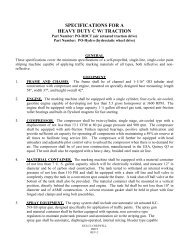
2000-AL Specifications - Kelly-Creswell
2000-AL Specifications - Kelly-Creswell
2000-AL Specifications - Kelly-Creswell
- No tags were found...

You also want an ePaper? Increase the reach of your titles
YUMPU automatically turns print PDFs into web optimized ePapers that Google loves.
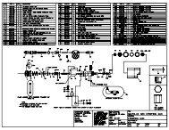
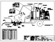
COMPRESSOR1. The compressor shall be a twin cylinder, single-stage, cast iron, air-cooled type having a minimum displacementof 13.1 CFM at 900 rpm at 100 pounds pressure.2. The compressor shall be equipped with a pneumatic automatic un-loader device and an air receiver.3. An adjustable pilot un-loader valve will be provided to unload compressor head when no demand for air.4. The compressor shall be conveniently mounted on the unit for easy daily maintenance and access.5. The compressor will be equipped with a replaceable air intake filter assembly.6. The main airline from the compressor to the air receiver shall be 1” diameter, heat resistant and equipped withreusable type fittings.7. The pulley and external belts of the compressor and engine shall be covered with a metal belt guard.HYDRAULIC SYSTEM1. A dedicated pressure-compensating piston pump shall exclusively supply hydraulic oil to the airless paint pump.2. The pump shall have a minimum capacity of 12 gallons per minute at 2,000 PSI.3. The pressure-compensating piston pump shall draw minimal horsepower until there is a demand for paint at theguns. The pump shall be directly coupled to an overhung load adapter to prevent side loading and excessivewear on the pump, attachment of a sheave directly to the hydraulic pump is not be permitted.4. The pump will be equipped with an automatic electronic actuated valve to unload hydraulic pressure buildupwhen the engine is being started.5. The airless hydraulic pump system will be equipped with a remote pressure adjusting valve located at the rearcontrol panel to control hydraulic pump pressure from 300-2,000 psi.6. An electronic actuated hydraulic valve will be provided to turn on/off hydraulic oil flow to the high pressureairless paint pump. Manual valves shall not be permitted.7. The hydraulic system shall be equipped with an oil cooler mounted directly in front of engine flywheel.8. The oil cooler will have a minimum of 107 square inches of cooling surface and equipped with a protectivesheet metal housing.HYDRAULIC RESERVOIR1. The hydraulic system will be equipped with a 16 gallon hydraulic reservoir of all steel construction.2. The reservoir shall be equipped with a vented breather cap, replaceable internal sump strainers with bypass, twoeach 1” hydraulic return filters with replaceable filter cartridges.3. The hydraulic tank will be unobstructed on all sides to quickly and evenly dissipate heat.4. The tank will be equipped with internal baffles and a sight level gauge.5. The tank will be mounted so that the inlet to the hydraulic pump(s) is flooded at all times.SECONDARY HYDRAULIC PUMP1. A second pressure compensated hydraulic pump will be provided for units equipped with optional hydraulicagitators and/or power steering.2. The pump will be directly coupled to the rear of the main hydraulic pump and provide hydraulic oil to thehydraulic agitators and power steering.3. The pump will be pressure compensated type with a capacity of 12 GPM at 2,000 psi.4. The pump will draw little horsepower until there is a demand for oil at the agitators or power outrigger steering.5. The pump will be equipped with a manual adjustable compensator.6. Units with only power steering will be equipped with a gear type pump with a capacity of 8GPM.7. The pump will be equipped with a safety pressure relief valve.KELLY-CRESWELL<strong>2000</strong>-<strong>AL</strong>REV C
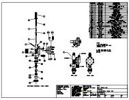
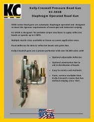
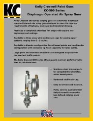
OUTRIGGER ASSEMBLY1. The gun carriage shall be attached to an outrigger that can trail from either the right or left rear side of the truck.2. The outrigger shall be easily positioned to either side of the truck by pulling a pin and pivoting the outrigger bymeans of a center pivot bearing.3. The outrigger will be equipped with two 1-1/4” pillow block bearings firmly bolted to the main frame of the unitacting as the main pivot point.4. The outrigger will feature a structural steel bumper with a UMHW liner to prevent the outrigger from saggingwhen changing from center to edgeline positions.OURTRIGGER STEERING: (Select A or B)A. Manual rack & pinion outrigger steering1. The outrigger will be equipped with manual rack & pinion steering assembly.2. A 1” gear rack will be welded to the internal tube of the outrigger, roller chain not acceptable.3. A hand wheel, approximately 12” in diameter will be provided to turn the gear rack assembly to position theoutrigger.4. The outrigger will be adjustable approximately 42”.5. The hand wheel will be easily accessible from either operator’s station.B. Hydraulic power outrigger steering.1. The outrigger shall be equipped with a hydraulic power steering system adjustable to any position within a36” operating range.2. The outrigger shall be steerable from either the right or left rear operator’s position by a conventionalautomotive-type steering wheel.3. Hydraulic quick disconnects will be provided to quickly and easily change hydraulic hoses when movingoutrigger from side/side.4. The hydraulic power outrigger steering will provide smooth continuous movement of the outrigger withouthesitation or jerk.5. The hydraulic power outrigger steering will get hydraulic power from a separate hydraulic pumpexclusively for the power steering system and/or power steering & hydraulic paint tank agitators.PAINT & BEAD GUNS1. The unit shall be equipped with two (2) KC-700-SS high volume, stainless steel, high pressure, automatic, airlessstriping guns, (no exceptions).2. The airless paint gun fluid chamber shall be constructed of stainless steel. The striping gun needle, needle ball,and seat shall be constructed of stainless steel and tungsten carbide.3. The striping guns shall be equipped with reversible tips and shall be interchangeable without the use of tools forvarious spray patterns and flow rates.4. The KC-700 spray guns will be mounted on an adjustable gun post for varying line widths and spacing betweenthe lines.5. The spray gun shall be small and compact for maximum visibility on the carriage, dimensions not to exceed 2.25”diameter x 6.75” long including tip guard.6. The Unit shall be equipped with two (2) automatic, diaphragm-operated KC-600 high capacity pressure beadguns.7. The KC-600 bead guns will be equipped with an adjustable shroud assembly to control the bead pattern width.8. One (1) bead gun shall be mounted directly behind each paint gun.9. The bead guns shall be capable of being operated simultaneously with the associated striping guns.KELLY-CRESWELL<strong>2000</strong>-<strong>AL</strong>REV C
10. The bead guns shall be fully adjustable for the desired application ratio of pounds of beads per gallon of paint.BEAD DISPENSING EQUIPMENT1. The Unit shall be equipped with a 750 pound capacity, carbon steel pressure bead tank, tested to a workingpressure of 110 psi.2. The bead tank lid shall have a minimum diameter of 10" and shall be held in place by four (4) over-the-centerclamp and screw assemblies with forged steel wing head bolts.3. The bead tank shall be equipped with a moisture trap with metal bowl, air pressure regulator, gauge, pop offvalve and air bleed jet. A full steel skirt shall be provided around the bottom of the tank for flush mounting to theplatform.4. Pressure bead hoses with a minimum diameter of 1-1/4" ID shall be provided to convey the beads from the beadtank to a bead distribution manifold located at the rear of the Unit. Pressure bead hoses from the distributionblock to the bead guns shall be 3/4" ID.5. The pressure on the bead tank shall be fully adjustable from the rear operators’ position via an air regulator andrelated gauge.ELECTRONIC SKIPLINE CONTROLLER1. The Unit shall include one Mark 40 D skipline controller system.2. The controller system shall be solid state, micro processor controlled and programmable.3. The controller system shall consist of an operator's control panel located at operator's position that includes all thenecessary components and controls for programming, pattern selection, and gun control.4. The control unit shall include one (1) two-line 32 character LCD display with adjustable contrast, one (1) fivepositionpush button programming panel, and nine (9) heavy duty military specification (MIL-S83731) toggletype switches with silicon rubber seals to prevent entry of contaminants.5. Toggle switch contacts shall be silver-to-silver and all metal parts shall be corrosion resistant to ensure longservice life and shall provide the following functions: master power, bead on-off, carriage lift/aux 1, auxiliaryskip pattern/aux 2, gun control for each striping gun (skip-off-solid) and reset-hold (master gun on-off).6. Programming the controller shall be possible through easy, menu driven procedures. All programminginformation shall be retained regardless of whether power is maintained.7. Paint/skip cycle - 0 - 999.9 feet. Two preset cycles shall be programmable and selected by the cycle auxiliarycycle switch. A quick edit feature shall allow simple adjustment to the skip cycle while painting is in process.8. Begin paint/skip. The controller shall be programmable to start with either the paint or skip portion of the cycle.9. Calibration. Calibration of the unit shall be programmable and simply achieved by driving a known distance andadjusting the displayed distance value.10. Bead delay (if purchased). Delay between the paint and bead gun on and off shall be programmable to assure fullcoverage by means of a mounting distance factor. Striping vehicle speeds shall not affect full bead coverage.Bead delay shall be factory preset and operator adjustable.11. Solenoid timing calibration. Solenoid timing delay shall be programmable to adjust for the reaction time ofdifferent solenoids and control hose lengths. Solenoid shall be factory preset and operator adjustable.12. Pattern change preset. The controller shall be programmable for three (3) different pattern change modes:immediate, smart and trigger.13. The Hold-Run-Reset control shall allow the operator to conveniently move through intersections and to permitretracing of old patterns.14. The Advance-Retard switch shall allow the operator to adjust the point at which the paint/skip cycle will begin.15. The Posi-Cycle feature, shall automatically adjust the cycle length after activating the Advance-Retard switchthree times.16. The controller shall be dust, water, and shock resistant. The operating range of the controller shall be from 30-125° F. Power shall be provided by the vehicles 12 volt supply. All cables shall be plug-in type and aweatherproof cover shall be included.17. In the ready mode, the controller shall display the skip line cycle, vehicle speed, painting in process indicator, andpulsed signal input indicator simultaneously. All footage display, whether cycle or skip length, odometerreadings, footage counter readings, or calibration readings are displayed to the nearest 1/10’. The controller shallbe capable of metric display.18. All programming and accumulated information, footage and odometer readings, and calibration settings shall beretained indefinitely upon power down (whether accidental or intentional) or removal of the controller from theKELLY-CRESWELL<strong>2000</strong>-<strong>AL</strong>REV C
vehicle. All information shall be stored in non-volatile RAM chips and do not require batteries to retainprogrammed information.19. The controller shall perform a complete self-test upon power up and alert the operator of short circuits.20. The controller shall be equipped with a low speed speedometer displaying operating speed in the LCD display.21. The controller shall be equipped with digital footage counters to totalize number of feet painted with each spraygun. The footage counters shall be re-settable to zero.22. The controller shall be equipped with a weatherproof vinyl cover to protect from moisture when not in use.PLUMBING AND HOSE LINES1. All plumbing lines from the material containers to the crossover manifold shall be ASTM specification 1 1/4" IDwith unions, crosses, and tees liberally used throughout the plumbing installation to ensure convenientmaintenance and cleanout.2. Plumbing from the crossover manifold to the airless pump inlet shall be 1-1/4" ID flexible Teflon core chemicalhose with stainless steel barbed fittings.HIGH PRESSURE AIRLESS PAINT HOSES1. All high pressure fluid hoses shall have a nylon core with a bonded urethane cover.2. The hoses shall be static free and equipped with static conductive tube.3. The hose shall be a minimum 3/8" I.D. with a minimum working pressure of 3,000 psi.4. The hoses will be equipped with stainless steel female swivel pipe ends.CONTROL HOSES1. All control lines to the striping guns and electro-air valves shall be not less than 1/4" ID solvent resistant tubing.2. All control lines shall use push-lock reusable fittings.HYDRAULIC HOSES1. All hydraulic pressure hoses shall be rated at a minimum of 2,500 psi working pressure.2. The hoses shall be equipped with a rubber cover resistant to tears.3. The fittings shall be crimp on type with JIC ends, pipe fittings are prohibited.4. Suction and return hoses shall be rated at 250 psi and equipped crimp type JIC fittings.5. Suction and return hoses with hose clamps are not permitted.CONTROL PANEL/AIR RECEIVER1. The Unit shall be equipped with a metal control panel located within reach of the rear operator.2. The control panel shall be equipped with: main air pressure gauge, on/off switch for airless paint pump, airregulator for pressure bead system, gauge for pressure bead tank, pressure reducing valve for hydraulic pump,gauge for hydraulic pump pressure and master electrical on/off switch.3. Controls located at or on individual components shall not be acceptable.4. Air regulators shall be non-corrosive, self-evacuating, and equipped with a locking device.5. A plastic legend will be provided to identify all components on the control panel.6. The legend will be marked from the reverse side to prevent fading and scratching.7. The legend will have the serial number inscribed and be permanently attached to the control panel with siliconeadhesive.8. Air moisture separator shall be provided to filter all air prior to passing through the air manifold.9. The moisture trap will have a metal bowl with manual drain cock.CONTROL SOLENOIDS1. The unit will be equipped with KC-C5 electro-pneumatic control valves.2. The control valves will control operation of paint guns, pressure bead guns and pneumatic carriage lift.3. The control valves will be installed on a common bolt together manifold base completewith o-ring seals.4. The solenoids shall be two position 4 way valves.KELLY-CRESWELL<strong>2000</strong>-<strong>AL</strong>REV C
<strong>2000</strong>-<strong>AL</strong>-00114-PTwo 75 gallon vats with 15 gal solvent, carbon steelconstruction*Hydraulic Power*Recommend for oil based paints onlyKELLY-CRESWELL<strong>2000</strong>-<strong>AL</strong>REV C
Optional EquipmentMaterialContainersAgitators,Hydraulic,VatAgitator,drummounted,pneumatic.Agitator,drummounted,hydraulicPaint & BeadGunsAC-AC-2150-1AC-2150-2AC-3040Carbon steel 60 or 75 gallon paint vats in lieu of stainless steel. Includes lowpressure plumbing and basket strainer (carbon steel). High pressure plumbingand airless hoses remain stainless. Recommended for application of exclusivelyoil based paints.Hydraulic driven paint vat agitators, stainless steel shafts and paddles, set oftwo. Includes additional hydraulic pump, needle valve controls to vary speed ofagitators. Two each paddle assemblies shall be installed one each agitator shaft.The paddle mount shall be a two piece design for ease or removal after paintbuilds up on shaft.Agitator, pneumatic drive for 55 gallon drum lid, one complete assembly.Includes bolt on fabricated assembly for air motor drive including 3/4"diameter stainless steel shaft two each stainless steel paddles. Air motorequipped with quick coupler, needle valve control and lubricator.Agitator, hydraulic drive for 55 gallon drum lid, one complete assembly.Includes bolt on fabricated assembly for hydraulic motor drive including 3/4"diameter stainless steel shaft two each stainless steel paddles. Hydraulic motorequipped with quick coupler and needle valve control.AC-2110 Additional KC-700 airless paint gun includes spray gun, gun hanger, gun post,fluid hose, KC-C5 actuation solenoid and airless paint hose.AC-2120 Additional KC-700 airless paint gun and KC-600 pressure bead gun includingguns hangers, guns posts, hoses, KC-C5 actuation solenoid, paint and beadhoses.AC-2130 Timed beads, separate solenoid supplied to control pressure bead gun. Thisinsures the entire painted line is covered with beads.Hand Paint AC-2145 Hand airless paint gun with 50’ ¼ static grounded airless spray hose. Spray gunand Beadequipped with HDPT-517 airless tip.GunsAC-1040 Hand bead gun with 25’ bead hose.AC-1040-1 Combination hand airless spray gun and pressure bead gun with retractablehose reel with 50’ of paint and bead hose. Bracket supplied to mount in unusedseat pocket on rear of unit.Intercom AC-<strong>2000</strong> Intercom system, model 78C with two each voice activated head sets. Driver’sheadset shall be a single ear and rear striper operators shall be a dual ear.AC-<strong>2000</strong>-1 Intercom system, model 78C with two each voice activated head sets. Driver’sheadset shall be a single ear and rear striper operators shall be a dual ear.Includes communication capability with other two way radiosPaint Loading AC-2060-1 Loading pump, 1” NPT air operated diaphragm pump, aluminum constructionwith two each 1” x 10’ loading hoses with quick disconnect fittings. A stingershall be provided to draw paint from a standard drum. Pump mounted to unitlocation determined by customer. Recommended for oil based paints only.AC-2060-2Loading pump, 1” NPT air operated diaphragm pump, stainless constructionwith two each 1” x 10’ loading hoses with stainless quick disconnect fittings. Astinger shall be provided to draw paint from a standard drum. Pump mountedto unit location determined by customer. Recommended for latex/waterbornepaints only.AC-2061 Two wheeled cart for loading pump (cart only).Storage Cart AC-2098 Cart assembly, four each heavy-duty leg that bolt to channel iron frame. Legsequipped with wheel for moving the unit on hard surface floor.Two Color AC-2 Color Unit equipped with second 8.6 GPM high pressure airless paint pump. IncludesUnitupgraded hydraulic system 20 GPM, upgraded engine Honda GX-690 34 grossHP. Unit manufactured on 60” wide frame in lieu of 48”.OtherOptionsKELLY-CRESWELL<strong>2000</strong>-<strong>AL</strong>REV C
Laser PointerStrobe LightDirectionalArrow-boardLaser guidance system, projects green dot on pavement surface for guidance.Available in manual and electronic adjustment.Amber strobe, 12VDC mounted on pole.Directional arrow-board with brackets to mount to tank or mount to rear offrame,24” X 48” with electronic tilt feature. Requires power from chassis.Vacuum bead loading system including vacuum pump, bead loading hose andcombination bead barrel & bag splitter.Optional trailer to mount the <strong>2000</strong>-<strong>AL</strong>.Night lighting package, 12VDC requires power from chassis.Factory direct technician for a period of one working day to instruct yourpersonnel in the operation and maintenance of the unit.Vacuum BeadLoading SystemTrailerNight LightsTraining On SiteTrainingSpare Parts <strong>2000</strong>-<strong>AL</strong> Minor Common replacement parts for <strong>2000</strong>-<strong>AL</strong>.<strong>2000</strong>-<strong>AL</strong> Major Replacement parts inventory recommended for export sales.KELLY-CRESWELL<strong>2000</strong>-<strong>AL</strong>REV C
KELLY-CRESWELL<strong>2000</strong>-<strong>AL</strong>REV C
KELLY-CRESWELL<strong>2000</strong>-<strong>AL</strong>REV C
KELLY-CRESWELL<strong>2000</strong>-<strong>AL</strong>REV C
KELLY-CRESWELL<strong>2000</strong>-<strong>AL</strong>REV C
KELLY-CRESWELL<strong>2000</strong>-<strong>AL</strong>REV C
KELLY-CRESWELL<strong>2000</strong>-<strong>AL</strong>REV C
KELLY-CRESWELL<strong>2000</strong>-<strong>AL</strong>REV C