
You also want an ePaper? Increase the reach of your titles
YUMPU automatically turns print PDFs into web optimized ePapers that Google loves.
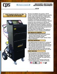
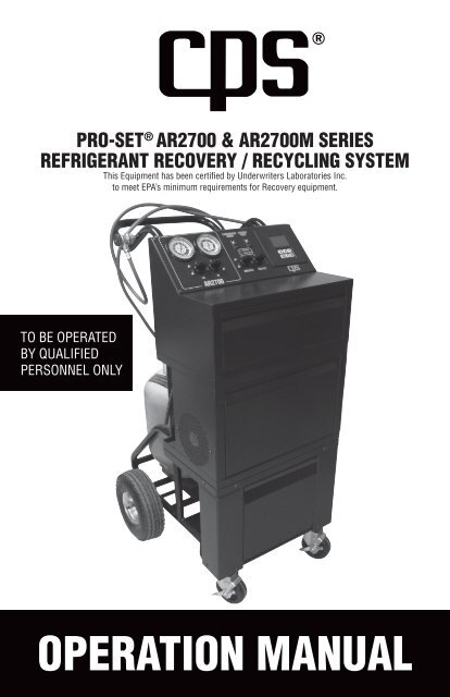
PRO-SET ® AR2700 & AR2700M SERIESREFRIGERANT RECOVERY / RECYCLING SYSTEMThis Equipment has been certified by Underwriters Laboratories Inc.to meet EPA’s minimum requirements for Recovery equipment.TO BE OPERATEDBY QUALIFIEDPERSONNEL ONLY<strong>OPERATION</strong> <strong>MANUAL</strong>
AR2700 & AR2700M SERIESSpecifications 2Introduction 3General Safety Instructions 4Unit Preparation 5-7Operation / Pump Down Operation 8-12Maintenance 13-16Parts List 17Warranty and Contact Information 19ModelsCompressor TypeDimensionsWeightOperating RangePower SourcePower ConsumptionSuction Pressure GaugeDischarge Pressure GaugeFiltrationManual Control ValvesCharging ValveConstructionTable Of ContentsAR2700 & AR2700M SpecificationsAR2700AR2700M115 VAC60Hz 1Ph2AR2700JAR2700MJ1/3 HP reciprocating compressor22" W x 24.5" D x 42" H120 lbs (does not include tank weight)0˚C (32˚ F) to 49˚C (120˚)100VAC50 / 60Hz 1Ph500 W-30 inch Hg to 125 PSIG0 to 500 PSIGAR2700EAR2700ME220-240VAC50/60Hz 1Ph16 cubic inch drier w/ moisture indicator, .7 micron oil separatorBall Type Valves to control HI, LO, Recover, and Vacuum12 VDC Solenoid Valve1" Heavy duty tubular frame construction10" pneumatic wheels, 4.5" swivel castersOverload Protection 15A Thermal Breaker 15A Thermal Breaker 10A Thermal BreakerHigh Pressure Shut-OffRefrigerants*30 bar (450 psig)R134a, R12, R22, R502, R404a, R402a, R401a, R407c, R409a* The AR2700, AR2700J, AR2700E does not contain a pump down valve and is meant for singlerefrigerant operation. The AR2700M, AR2700MJ, AR2700ME contains a pump down valve formutiple refrigerant usage. Mixing of refrigerants will cause the user economic loss.
INTRODUCTIONThank you for purchasing the <strong>CPS</strong> PROSET ® AR2700 & AR2700M series refrigerantrecovery / recycling / recharge unit. <strong>CPS</strong> is dedicated to give you the most reliableequipment to meet all your mobile refrigerant recovery/recycling requirements.The following are features of the AR2700:••••••••••••••Automatic programmable chargingLo side or Hi side or Hi / Lo side chargingNon-restrictive heavy duty ball type control valvesOn board HI and LO gauges and valves for manifold function16 cubic inch filter drier with moisture indicator.7 micron oil separator filter to collect and measure oil removed fromthe mobile A/C system1" Heavy duty tubular steel frame with powder coated steel cabinetryLarge 10" pneumatic wheels with 4.5" swivel casters for easy maneuverabilityR134a couplers and refill adaptorsCan be dedicated to one of several refrigerants. See specification list forapproved refrigerantsBuilt in condenser for high ambient operationBuilt in evaporator to protect the compressor against flood-backAR2700M series includes a pump down valve for multiple refrigerant useManual oil injection system (Removable)To help you get a good start, please continue to carefully read the balance of thismanual. This manual contains important information on the proper procedures foroperating this equipment. Please pay close attention to the safety information,Warnings, and Cautions provided throughout this manual. Always remember“Safety First”.This equipment meets or exceeds SAE J1990 and J1991 for R12 and SAE J2099 and J2099 for R134A3
GENERAL SAFETY INSTRUCTIONSOnly qualified service personnel should operate this unit. Most states, countries,etc… may require the user to be licensed. Please check with your local governmentagency.DANGER- The recovery tank used with this unit contains liquid refrigerant.Overfilling of the recovery tank may cause a violent explosion resulting in severe injuryor even death. Please carefully read Tank Parameters Setting section on page 4of this manual. Do not proceed to use the unit until the tank settings have beenproperly set.DANGER- Avoid breathing refrigerant vapors and lubricant vapor or mist. Breathinghigh concentration levels may cause heart arrhythmia, loss of consciousness, or evencause suffocation.DANGER- ELECTRICAL SHOCK HAZARD Always disconnect power source whenservicing this equipment.DANGER- EXPLOSION RISK. Do not recover flammable refrigerants.CAUTION- All hoses may contain liquid refrigerant under pressure. Contact withrefrigerant may cause frostbite or other related injuries. Wear proper personalprotective equipment such as safety goggles and gloves. When disconnecting anyhose, please use extreme caution.CAUTION- Avoid breathing refrigerant vapors and/or lubricant mist. Exposure mayirritate eyes, nose, throat, and skin. Please read the manufacturers Material Safety DataSheet for further safety information on refrigerants and lubricants.CAUTION- To reduce the risk of fire, avoid the use of extension cords thinner thanNO. 14 awg. (1,5mm²) to prevent the overheating of this cord please keep length to aminimum.CAUTION- Do not use this equipment in the vicinity of spilled or open containers ofgasoline or other flammable substances. Make certain that all safety devices arefunctioning properly before operating the equipment.CAUTION- This equipment should be used in locations with mechanical ventilation thatprovides at least 4 air changes per hour or the equipment should be at least 18" abovethe floor.This equipment is intended for use of one refrigerant. Mixing of different refrigerantswill cause your recovered supply of refrigerant to become contaminated.Note: Ecomonic loss will occur when disposing of mixed refrigerants.4
UNIT PREPARATIONUnpack unit. Locate the scale platform contained in the accessoy box. Place scaleplatform onto the craddle as shown in picture below. Plug cable into scale port.Install user (purchased separately) supplied tank onto scale platform. <strong>CPS</strong> sellsCRX50T (50# DOT Tank) and CRX390T (92# DOT Tank) tanks that can be used withthis unit. Make sure the tank is centered on scale platform and not touching theframe or any hoses.Unit Consists Of:••••••••••Pro-Set ® model AR2700 R/R/R unitPower cord set8' service hosesSet of R-134a snap couplersR-134a tank refill adaptorsVacuum pumpMagnetic tank thermometerTank purge valve w/ gaugeOperation manualManual oil injection system5
UNIT PREPARATIONThe Empty Tank Weight (ETW) and Maximum Refrigerant Weight (MRW) of the userprovided recovery tank needs to be inputted into the AR2700 electronic database. Thefollowing are the steps required to set the ETW and MRW into the AR2700 memory.DANGER!!!! Failure to set the Tank Parameters correctly can lead to overfilling ofthe on board recovery cylinder. SEE GENERAL SAFETY INSTRUCTIONS for results ofoverfilled tank.1.2.3.4.5.6.7.8.9.10.11.12.Setting The Tank ParametersTurn the unit on while pressing the GO/HOLD key unit until the LCD displays theletter “U” on the upper left hand corner.Press the “LB/KG” key to select between IMPERIAL and METRIC units.Press the GO/HOLD key.The display shows the letter “E” on the upper left hand corner fora couple of seconds.The display shows the default (ETW) for a 50 pound tankin the units selected. (SEE CHART BELOW)The user can then use the UP ARROW or DOWN ARROW keys toadjust the (ETW) of the tank being used.The user then pushes the GO/HOLD key again.The display shows the default Maximum Refrigerant Weight for a 50 poundtank in the units selected above.The user pushes the UP ARROW or DOWN ARROW keys to adjust the (MRW).The user pushes the GO/HOLD key again.The display shows “DONE”.The user pushes the GO/HOLD key again to go to the normal displayor turns the machine OFF.The following table are ETW and MRW settings for tanks sold by <strong>CPS</strong>. Always refer tothe tank manufacturers information stamped into the collar of the tank.<strong>CPS</strong> Tank ETW MRWCRX400T (50 lbs) 28 lbs, 10 oz 38 lbs, 0 ozCRX390T (90 lbs) 57 lbs, 8 oz 68 lbs, 0 oz<strong>CPS</strong> 40L (EU) 46 lbs, 2 oz 74 lbs, 4 oz*ETW= Tare Weight (TW) on Tank Collar, **MRW=Water Capacity (WC) of tank x 0.806
UNIT PREPARATIONInstalling Filter Bracket, Filter Drier Associated HosesInstall Universal Filter / Tank bracket onto top oftank. Use the provided wire ties to hold the UniversalFilter / Tank bracket to the collar of the tank. Installfilter drier onto Universal Filter / Tank bracket. UseVelcro straps to secure the filter drier to theUniversal Filter / Tank bracket.Secure filter bracket to tank collarwith the use of the provided nylon ties2143576The unit has three hoses that need to be installed:Blue Hose with Ball Valve, Red Hose with Ball valve,and short red hose. Connect both the Blue and Redhoses with Ball Valves to the back of the AR2700 asshown in the picture. Connect the other end of theBlue Hose to the Tank Vapor Port. Connect the otherend of the Red Hose with ball valve to the Filter Drieroutlet port. Install the Short Red hose from the TankLiquid Port to the Filter Drier Inlet port as shown inthe picture. Use a 9/16" wrench to tighten thisfittings. Open all Tank and Hose valves.Check for leaks.Unit Guide:1.2.3.4.Blue hose with BVRed hose with BVTank vapor valveFilter outlet5.6.7.Tank liquid valveShort red hoseFilter inletCheck vacuum pump oil level. Add oil if necessary.Slide vacuum pump out on its tray for easier access.Check tool drawer for accessories such as tank refilladaptors and low side charging adatpor.Proceed to Tank Refill Function on page 10. It will benecessary to fill the refrigerant storage tank beforecharging operation can take place.7
<strong>OPERATION</strong>Turn main power switch ON. The power switch is located on back left hand corner ofunit. The AR2700 LCD will show the current refrigerant amount in storage tank. Openboth liquid and vapor tank and hose valves.Manifold Function:1.2.Connect HI and LO side service hoses to A/C system. Open service hose valves.Keep both HI and LO manifold valves in the closed (I) position.Start A/C system. Gauges will show system pressures of the A/C.Recover Function:1.2.3.4.5.6.7.8.9.Connect HI and LO Side service hoses to A/C system. Open the servicehose valves.Push the TARE key on Scale keypad unit until zero reading is shown.Open (O) both the HI and LO manifold valves.Turn COMPRESSOR switch to ONTurn the RECOVER VALVE to open (O) position.Monitor the gauges for A/C system pressure.Once below -5" hg. vacuum, Close (I) the RECOVER, HI and LO manifold valves.Turn the COMPRESSOR switch to OFF. Wait 5 minutes. If pressure rises above0 PSIG, repeat Step 4-8.Record weight on LCD. Push the TARE key to return scale to the currentrefrigerant weight.10. Slowly open oil drain valve until oil/refrigerant mixture is released into the oil drainbottle. Both are located on the lower left hand side of the unit. If no oil is draining,close oil drain valve. Recovery Complete.Vacuum Function: Before running the vacuum pump, the A/C system must have asystem pressure of 2 PSIG or lower. If pressure exists, go to Recover Function first.1.2.3.4.5.6.7.Connect HI and LO side service hoses to A/C ports. Open the service hose valves.Open (O) both the HI and LO manifold valves.Turn the VACUUM PUMP switch to ON.Open (O) the VACUUM valve.Run vacuum pump until desired vacuum level is achieved.Close (I) the VACUUM, HI and LO manifold valves.Turn the VACUUM PUMP switch to OFF. Vacuum Complete.Oil Injection Function: Oil Injection can be performed once vacuum is complete.Make sure there is a minimum of 6 ounces in the Oil Injection Bottle to ensure no airgets back into the A/C system.1.Open high side manifold valve.8
<strong>OPERATION</strong>2.3.4.Open the oil injection valve. Note: the oil level in the oil injection bottle.Once the required amount of oil has been injected, close injection valve.Proceed immediately to Charge Function.Charge Function: Before running the charge function, the A/C system should be ina deep vacuum.1.2.3.4.5.6.7.8.Connect HI and LO side service hoses to A/C system.Open the service hose valves.Open (O) HI manifold valve only. Keep LO manifold valve closed.Push the SET/RESET key on scale keypad until the LCD displays “READY”and charge amount.Push LB/KG Key on scale keypad to select LBS or KGS units of measure.Use the UP or DOWN arrow keys to set the charge weight. Note: If the unitalarms, the remaining refrigerant capacity has been reached.Push the GO/HOLD key. The unit will begin to automatically charge theA/C system.The LCD will show refrigerant being dispensed.Once amount shown on LCD meets the programmed amount, the charging willautomatically stop and the unit will beep. Go to Step 9.If the programmed charge weight is not reached (The unit will alarm if there is norefrigerant flow for more than 3 minutes) on LCD follow steps A-D:A.B.C.D.Close (I) the HI manifold valve.Start A/C System.Open (O) LO manifold valve.Once programmed charge amount is reached, the charging will automaticallystop and the unit will beep.The following is hose purge sequence to ensure no residual liquidrefrigerant is left in the service hoses:9.10.11.12.Remove the HI side service hose from the A/C system.Start A/C System.Open (O) both LO and HI manifold valves. Once LO and HI manifold gauges arereading the same pressure, hose purge is complete.Disconnect LO side service hose from A/C System.“TOP OFF” Charge Function: This procedure is used to add additional refrigerant to apre-charged A/C system.1.2.Connect HI and LO side service hoses to A/C system.Open the service hose valves.Start A/C system.9
CHARGE CONT. / TANK REFILL <strong>OPERATION</strong>3.4.5.6.7.8.9.Push the SET/RESET key on scale keypad until the LCD display “READY”and charge amount.Push LB/KG key on scale keypad to select LBS or KGS units of measure.Use the UP or DOWN arrow keys to program the desired “TOP OFF” weight.Push the GO/HOLD key.Open (O) LO manifold valve only. Keep HI manifold valve closed.The LCD will begin to show refrigerant being dispensed and automaticallyshut off once complete.Monitor A/C system pressures. Repeat Step 3-7 if more charge is required.Tank Refill Function:1.2.3.4.5.6.7.8.9.10.Turn main power switch ON. The power switch is located on back left handcorner of unit.Connect HI side service hoses to refrigerant supply tank.Keep supply tank upright.Open the HI side service hose valve. Open supply tank valve.Push the GO/HOLD key on scale keypad. LCD will show available refrigerantspace in the tank. Open HI side manifold valveTurn the COMPRESSOR switch to ON. Open (O) the RECOVER valve.Turn supply tank upside down after 2 minutes of refilling.The LCD will begin to count down. If the LCD countdown reaches zero, the unitwill alarm with a (RF done) message on the LCD. The compressor will be shut offand the refill function is complete.Close valve on supply tank. Close (I) the RECOVER and HI manifold valves.Turn the COMPRESSOR switch to OFF.Push the GO/HOLD key to return scale function to normal operation.If the LCD countdown stops in Step 5, the supply tank is empty. Replace supplytank and continue from Step 5 or go to Step 7 to shutdown the refill function.10
PUMP DOWN <strong>OPERATION</strong>Pump Down Function (AR2700M Series Only):1.2.3.4.5.6.7.8.9.10.11.12.13.Make sure service hoses are disconnected fromAC system.Turn the low and high side manifold valves to theopen position.Locate the pump down lever on the back of themachine and move to the Pump Down position(UP) as shown in the picture.Close the liquid valve on tank.Turn the compressor ON and turn the recovery valve to the open position.Push the SET/RESET key on scale keypad.Use the UP or DOWN arrow keys to program 10 lbs or 5 kgs.Push the GO/HOLD key to initiate filter pumpdown.Monitor the gauges until they read 10" Hg vacuum.If the unit begins to beep before you have reached 10" Hg vacuumpush reset and repeat steps 7-10.Once the machine reads 10" Hg vacuum turn the compressor off, turn vacuumvalve to the open position and start vacuum pump.Run vacuum pump for a minimum of 10 min to remove any residual refrigerant.Turn the vacuum pump switch OFF and close (I) the vacuum and compressormanifold valves. Pumpdown is now complete. Disconnect hoses from the tank.The unit is now ready for a new tank of an approved refrigerant. Please makesure to return the pumpdown valve to the normal position.Pump Down Position (UP)11
TROUBLE SHOOTING / <strong>OPERATION</strong>High Pressure Indication - During recovery or tank refill if a high pressure conditiontrips the HP limit switch, the compressor relay is deactivated, an alarm sounds and thescreen shown below is displayed.HPOLkggSolution: Check that both tank valves and both tank hosevalves are open.Solution: Run the air purge routine. Presence of air inrecovery tank can cause high pressure to exist.Tank Overfill Indication - During recovery if the weight of the refrigerant in the tankexceeds the maximum refill refrigerant weight the compressor relay is deactivated andpower is disconnected from the compressor. The message below is displayed and thealarm is sounded.rCOLkggSolution: Make sure tank settings were properly inputted.Solution: Run Charge mode, Charge 10 lbs. of refrigerantinto an evacuated cylinder. Save for future use.At anytime, and regardless of the units chosen or the level of tare, if more than 100 kgor 220.5 lb is placed on the weighing platform, an overload message is displayed asshown below.OLlbsozSolution: Make sure the tank used when full will notexceed 220 lbs maximum.Solution: Check scale calibrationCompressor Fails To StartUnit’s Compressor Fails to Start - If the compressor is unequalized, it may not start.To equalize, open oil drain valve for 10 seconds then close. Try restarting compressor.12
MAINTENANCERecycling Maintenance - NCG Purge ProcedureIt will be necessary to purge the recovery tank of non-condensable gases (NCG’s). TheNCG’s are picked up from leaks in a/c systems when performing the RecoveryFunction. The best time to check for purging is first thing in the morning before usingthe unit or 30 minutes after the last Recovery operation. The following is a step by stepof the air purge procedure:1.2.3.4.A.B.Read the tank temperature via the providedmagnetic thermometer.Read the pressure on the purge valveassembly mount on the tank.Use the NCG’s purge table below todetermine if the refrigerant in therecovery tank needs to bepurged of NCG’s. See Examples 1 and 2.If purging is required:Open the purge valve for 15 seconds to vent theNCG’s. Then close valve.Read purge gauge to see if the pressure of thetank falls below the NCG Gases purge table.If no, repeat step 4A.21Example 1R-134 Tank Temperature = 76 FR-134 Tank Pressure = 86 psigMaximum Pressure (from Table)= 90.3 psigNo NCG purging required.Example 2R-134 Tank Temperature = 88 FR-134 Tank Pressure = 120 psigMaximum Pressure (from Table)= 110.7 psigPurge NCG’s until Tank Pressure isbelow 110.7 psig.13
MAINTENANCEMaximum Refrigerant Vapor Pressure Chart (Temp F/C vs. Pressure psig)TemperatureRefrigerant Vapor Pressure (psig)F C R-12 R-134a R-22 R-502 R-404a R-402a R-401a R-407c R-409a32.0 0.0 40.1 37.8 67.5 78.4 82.3 88.3 37.9 68.2 37.634.0 1.1 41.7 39.5 70.1 81.3 85.4 91.6 39.6 73.4 39.236.0 2.2 43.4 41.3 72.8 84.3 88.5 95.0 41.3 79.0 40.938.0 3.3 45.2 43.2 75.6 87.4 91.8 98.5 43.2 83.1 42.740.0 4.4 46.9 45.1 78.5 90.5 95.1 102.1 45.0 86.5 44.542.0 5.6 48.8 47.0 81.5 93.8 98.5 105.7 47.0 89.5 46.344.0 6.7 50.7 49.1 84.5 97.0 101.9 109.5 49.0 93.1 48.246.0 7.8 52.7 51.1 87.6 100.4 105.5 113.4 51.0 96.3 50.248.0 8.9 54.7 53.3 90.7 103.9 109.2 117.3 53.1 101.0 52.250.0 10.0 56.7 55.5 94.0 107.4 112.9 121.4 55.3 104.5 54.352.0 11.1 58.8 57.7 97.3 111.0 119.0 130.0 70.0 108.2 73.654.0 12.2 61.0 60.1 100.8 114.8 123.0 134.0 72.0 112.3 76.256.0 13.3 63.2 62.3 104.3 118.6 127.0 139.0 75.0 116.5 78.958.0 14.4 65.4 65.0 107.9 122.4 131.0 143.0 78.0 120.7 81.660.0 15.6 67.7 67.5 111.6 126.4 135.0 148.0 80.0 124.9 84.562.0 16.7 70.1 70.1 115.4 130.4 140.0 152.0 83.0 129.2 87.364.0 17.8 72.5 72.7 119.3 134.6 144.0 157.0 86.0 133.5 90.366.0 18.9 75.0 75.5 123.2 138.8 149.0 162.0 89.0 138.2 93.368.0 20.0 77.6 78.3 127.3 143.2 154.0 167.0 92.0 143.0 96.470.0 21.1 80.2 81.2 131.4 147.6 158.0 170.4 95.0 147.6 99.572.0 22.2 82.9 84.2 135.7 152.2 163.0 178.0 99.0 152.2 102.874.0 23.3 85.6 87.2 140.0 156.8 168.0 183.0 102.0 157.1 106.076.0 24.4 88.4 90.3 144.5 161.5 174.0 189.0 105.0 162.0 109.478.0 25.6 91.3 93.5 149.0 166.3 179.0 194.0 109.0 168.0 112.980.0 26.7 94.2 96.8 153.6 171.2 184.0 200.0 112.0 174.1 116.482.0 27.8 97.2 100.2 158.4 176.2 190.0 203.6 116.0 180.6 120.084.0 28.9 100.2 103.6 163.2 181.4 195.0 212.0 119.0 186.6 123.786.0 30.0 103.3 107.1 168.2 186.6 201.0 218.0 123.0 192.2 127.488.0 31.1 106.5 110.7 173.2 191.9 207.0 224.0 127.0 198.4 131.290.0 32.2 109.8 114.4 178.4 197.4 213.0 230.0 131.0 204.6 135.192.0 33.3 113.1 118.2 183.7 202.9 219.0 237.0 135.0 210.6 139.194.0 34.4 116.5 122.1 189.1 208.6 225.0 244.0 139.0 216.6 143.296.0 35.6 120.0 126.1 194.6 214.3 232.0 250.0 143.0 222.6 147.498.0 36.7 123.5 130.1 200.2 220.2 239.0 257.0 148.0 228.6 151.6100.0 37.8 127.2 134.3 205.9 226.2 245.0 264.0 152.0 234.6 156.0102.0 38.9 130.9 138.5 211.8 232.3 252.0 271.0 156.0 240.7 160.4104.0 40.0 134.7 142.9 217.7 238.5 259.0 279.0 161.0 246.8 164.9106.0 41.1 138.5 147.3 223.8 244.9 266.0 286.0 166.0 252.9 169.5108.0 42.2 142.4 152.8 230.0 251.3 274.0 294.0 170.0 259.0 174.2110.0 43.3 146.4 156.5 236.4 257.9 281.0 302.0 175.0 265.1 179.0Bold - indicates liquid pressure due to blend14
MAINTENANCEThe AR2700 series is equipped with 16 cubic inch filter drier with moisture indicator.This filter should be replaced when the indicator showsCaution or Wet.For the AR2700M series, the Pump Down instructionson page 10-11 can also be used to change the filter.Replace the filter drier as follows:1.2.3.4.5.6.7.8.9.10.11.13.14.Maintenance- Filter Drier Change ProcedureClose Tank Liquid Valve.Push the SET key on the keypad.Use UP/DOWN keys to set charge amount to 2 lbs. Filter IndicatorPush the GO key.Push the COMPRESSOR switch to ON.Turn the RECOVER valve to open (O) position.Turn the HI and LO manifold valves to open (O) position. The refrigerantin the filter drier is now being recovered.After 5 minutes, Check the HI and LO gauges to see if a vacuum has beenreached. If vacuum has not been reached, continue running.Once a vacuum has been reached, close (I) the RECOVER, HI and LOmanifold valves.Turn the COMPRESSOR switch to OFF.Push the RESET key on the keypad.12.Open tank liquid valve and check for leaks.Filter change is now complete.The filter has now been pulled into a vacuum andcan be safety removed and replaced. Replace thefilter with <strong>CPS</strong> p/n ARXF2. Make sure the arrowon the new filter drier is pointing away from thetank liquid port.15
MAINTENANCE1.2.3.4.Additonal MaintenanceCheck Vacuum Pump Oil level before using the unit. If level is low, add. If oil turnsyellowish-brown, change oil.Check service hose gaskets and o-rings for wear. Replace if necessary.Check o-ring seal in Couplers for wear. Replace if necessary.Check to make sure the oil drain system is function. Open drain valve and check forfailure to perform the oil drain function after each recovery, could lead to excessiveoil in the compressor and eventual compressor slugging.Exhaust / Refill CapOil SightglassOil DrainInterconnection Hoses, Service Hoses and Coupler MaintenanceThe AR2700 series uses brass to brass seal type fitting on the ends of the internalinterconnecting hoses. No hose gasket maintenance is required on the brass to brasstype of connections. Periodically inspect the refrigerant hose assembly, both servicehose ends and both service couplers (if used) inner O-ring. Replace the component(s)if excessive wear or leakage is observed. Periodically leak-check all hose connectionpoints, hose ball valves, and service couplers (if used). Since this unit does pull avacuum in the recovery process, excessive Non-Condensable Gases (NCG’s) could besucked into the system and placed in the storage tank.16
PARTS LIST<strong>CPS</strong> P/NAFXF2AR2788SX28ARH50ARH52ARH68ARH69ARX27CMP115ARX27CMP230ARX27CSVARX27MNFARX27PCBARX27PSARX27SCLCRX390TCRX400TQCH90QCL90T-40LVPOQDescription16 oz Filter Drier w/ Moisture Sight GlassOil Injector AssemblyRefill Hose 134A Low Side Nipple x 1/4" SAE Female SwivelRefill Hose 134a Low Side Nipple x 1/2" ACME Female Swivel8' Blue Service Hose8' Red Service HoseAR2700 115 Volt Service CompressorAR2700 230 Volt Service CompressorAR2700 Charging Solenoid Valve Operator, 12VDCAR2700 Manifold/Control Panel AssemblyAR2700 Scale/Keypad Control ModuleAR2700 Power SupplyAR2700 Scale Platform92# DOT Recovery Cylinder50# DOT Recovery CylinderHigh Side CouplerLow Side CouplerEuropean Approved 40 Liter TankVacuum Pump Oil (Quart)17
NOTES18
WARRANTY / CONTACT INFORMATIONWARRANTY & REPAIR POLICY<strong>CPS</strong> <strong>Products</strong>, Inc. guarantees that all products are free of manufacturing and material defects tothe original owner for one year from the date of purchase. If the equipment should fail during theguarantee period it will be repaired or replaced (at our option) at no charge. This guarantee does notapply to equipment that have been altered, misused or solely in need of field service maintenance. Allrepaired equipment will carry an independent 90-day warranty. This repair policy does not includeequipment that is determined to be beyond economical repair.<strong>CPS</strong> GLOBAL LOCATIONS<strong>CPS</strong> PRODUCTS, Inc. (WORLD HEADQUARTERS)1010 East 31st Street, Hialeah, Florida 33013, USATel: 305-687-4121, 1-800-277-3808, Fax: 305-687-3743E-mail: cpssales@cpsproducts.com www.cpsproducts.com<strong>CPS</strong> CANADA4605 Crysler Ave. Niagara Falls, Ontario L2E 3V6Tel: 905-358-3124, Fax - 905-358-7187, 1-866-629-3895,E-mail: cpscanada@bellnet.ca<strong>CPS</strong> PRODUCTS N.VKrijgsbaan 241, 2070 Zwijndrecht, BelgiumTel: (323) 281 30 40, Fax: (323) 281 65 83, www.cpsproducts.be,E-mail: info@cpsproducts.be<strong>CPS</strong> AUSTRALIA PTY. LTD.109 Welland Avenue, Welland, South Australia 5007Tel: +61 8 8340 7055, Fax: +61 8 8340 7033E-mail: sales@cpsaustralia.com.au<strong>CPS</strong> ASIA56A Kallang Pudding Road #02-00 Singapore Road 349329Tel: (65) 68461056, Fax: (65) 68461054E-mail: cpsasia@singnet.com.sg19
www.cpsproducts.com#73-064 Rev C