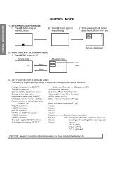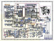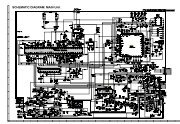
4-2-2 How to Access Service Mode - Turuta Electronics World
4-2-2 How to Access Service Mode - Turuta Electronics World
4-2-2 How to Access Service Mode - Turuta Electronics World

You also want an ePaper? Increase the reach of your titles
YUMPU automatically turns print PDFs into web optimized ePapers that Google loves.
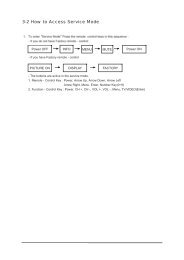
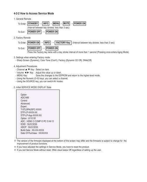
4-2-2 <strong>How</strong> <strong>to</strong> <strong>Access</strong> <strong>Service</strong> <strong>Mode</strong>1. General RemoteTo Enter: STANDBY → INFO → MENU → MUTE → POWER → ON(Interval between key strokes: less than 3 sec)To Exit: POWER OFF → POWER ON2. Fac<strong>to</strong>ry RemoteTo Enter: POWER ON → INFO → FACTORY → Key (Interval between key strokes: less than 3 sec)To Exit:POWER OFF → POWER ONPress the Fac<strong>to</strong>ry key twice with a key stroke interval of more than 1 second (Pressing once enters Aging <strong>Mode</strong>)3. Settings when entering Fac<strong>to</strong>ry mode- Sharp Screen (Dynamic), Color Tone (Cool1), Fac<strong>to</strong>ry (Dynamic CE Off), DNIe(Off)4. Adjustment Procedures- Channel ▲▼Key : Select an item.- Volume ◀▶ Key : Adjust the value up or down.- MENU Key : Save the changes <strong>to</strong> the EEPROM and return <strong>to</strong> the higher-level mode.- Using the Numeric (0~9) keys, you can select a channel.- Using the SOURCE key, you can switch AV modes.5. Initial SERVICE MODE DISPLAY StateOptionADC/WBControlAdvancedExpertT-STL5PAUSFC-XXXXDTP-LP-XXXX-XXDTP-LP-App-XXXX-XXOption : 6110 00ADC : HDMI O COMP O PC O AV OEDID : SUCCESSHDCP : SUCCESSBuild Date : XX-XX-XXXXDate Of Purchase : XX/XX/XX※ The version of the firmware displayed at the bot<strong>to</strong>m of the screen may differ and the firmware is subject <strong>to</strong> change for theimprovement of product functions.※ If you have adjusted the settings in <strong>Service</strong> <strong>Mode</strong>, you have <strong>to</strong> reset the product.※ If you exit <strong>Service</strong> <strong>Mode</strong> without reset, DNIe vlaue keeps Off regardless of setting up the user.
4-2-3 Fac<strong>to</strong>ry Data1. OptionItem Data RangeFac<strong>to</strong>ry ResetType58FNfK1<strong>Mode</strong>l PB550 PB560/PB550/PB530/PB450/PB430/PB540/PB420/PB410TUNERRegionDDR Off On / OffLight Effect Off On / OffInch 58" 32" / 37" / 40" / 46" / 52"LCD/PDP PDP LCD / PDPExhibition <strong>Mode</strong> Off On / Off2. ADC/WBADCItem Default data RangeAV Calibration Success Success / FailureComp Calibration Success Success / FailurePC Calibration Success Success / FailureHDMI Calibration Success Success / FailureADC TargetItem Default data Range1st_AV_Low 18 0 ~ 2551st_AV_High 220 0 ~ 2551st_AV_Delta 1 0 ~ 2551st_COMP_Low 16 0 ~ 2551st_COMP_High 235 0 ~ 2551st_COMP_Delta 1 0 ~ 2551st_PC_Low 2 0 ~ 2551st_PC_High 253 0 ~ 2551st_PC_Delta 1 0 ~ 2552nd_Low 1 0 ~ 2552nd_High 235 0 ~ 2552nd_Delta 1 0 ~ 255
ADC RESULTFac<strong>to</strong>ry NameDefault dataAV / RF Component HDMI / DTV / HDMI-PC PCRange1st_AV_Gain 136 134 136 192 0 ~ 2551st_AV_Offset 136 134 136 192 0 ~ 2551st_Comp_Gain 136 134 136 192 0 ~ 2551st_Comp_Gain_Cb 107 67 100 32 0 ~ 2551st_Comp_Gain_Cr 107 67 100 32 0 ~ 2551st_Comp_Offset 107 67 100 32 0 ~ 2551st_Comp_Offset_Cb 136 134 136 192 0 ~ 2551st_Comp_Offset_Cr 136 134 136 192 0 ~ 2551st_PC_R_Gain 136 134 136 192 0 ~ 2551st_PC_G_Gain 107 67 100 32 0 ~ 2551st_PC_B_Gain 136 134 136 192 0 ~ 2551st_PC_R_Offset 136 134 136 192 0 ~ 2551st_PC_G_Offset 136 134 136 192 0 ~ 2551st_PC_B_Offset 107 67 100 32 0 ~ 2552nd_R_Offset 107 67 100 32 0 ~ 2552nd_G_Offset 107 67 100 32 0 ~ 2552nd_B_Offset 136 134 136 192 0 ~ 2552nd_R_Gain 136 134 136 192 0 ~ 2552nd_G_Gain 136 134 136 192 0 ~ 2552nd_B_Gain 107 67 100 32 0 ~ 255WBFac<strong>to</strong>ry NameDefault dataAV / RF Component HDMI / DTV / HDMI-PC PCSub Brightness 128 128 128 128R_Offset 512 512 512 512G_Offset 512 512 512 512B_Offset 512 512 512 512Sub Contrast 128 128 128 128R_Gain 512 512 512 512G_Gain 512 512 512 512B_Gain 512 512 512 512Movie R Offset 128 128 128 128Movie B Offset 512 512 512 512Movie R Gain 512 512 512 512Movie B Gain 512 512 512 512Range
3. ControlEDIDItem Default data RangeEDID ON/OFF Off On / OffEDID WRITE ALL Success Success / FailureEDID WRITE Success Success / FailureEDID WRITE Success Success / FailureEDID WRITE Success Success / FailureEDID WRITE Success Success / FailureEDID WRITE Success Success / FailureEDID VERSION HDMI 1.3 HDMI 1.2 / HDMI 1.3
Sub OptionItem Default data RangeMute Time(VIDEO) 4 0 ~ 10ready Failure Success / FailureHotplug On On / OffHotplugcontrol On On / OffSpread SpectrumAu<strong>to</strong> Power On On / OffDDRArab Off On / OffNT Conversion Off On / OffMirror On On / OffHDMI EQ1 Middle Low / Middle / High / StrongHDMI EQ2 Middle Low / Middle / High / StrongHDMI EQ3 Middle Low / Middle / High / StrongHDMI EQ4 Middle Low / Middle / High / StrongEER CountWM CalibPanel Enter KeyPanel Display TimeCHECKSUMView LogFont Data Viewer0Hr0x0000Dimm Type EXT INT / EXT / INT_NEG / INT_POSGamma Off Off / 0.85 / 0.88 / 0.90 / 0.93 / 0.95 / 0.98Carrier Mute on On / OffAnynet+ On On / OffHPD PolarityHigh Devi Off On / OffVolum Curve NT NT / EU / EAHotPlug Delay 9 0 ~ 63HP Ident Low Low / HighPC Ident On On / OffLanguageInfo LiveChinaWatchdog On On / OffLVDS Format VESA JEDIA / VESAOSD Resolution 1920*1080Bus S<strong>to</strong>pOTA CodePanel Au<strong>to</strong> SettingOTA Duration TestAlternate DelIgnore VCT Version Off On / Off
PDP OptionItem Default data RangePIXEL SHIFT TEST Off on/offLOGIC CONNECT off on/offPATTERN SELECT(Logic Board)PANEL VERSIONPANEL INCHPANEL TYPE0UF1A58FHD92HPANEL TEMPERATURE 31LOGIC SW VERSIONLOGIC SW CHECKSUMxx-xx-xx371HSAPC_Timer On on/offAPC_Speed Slow Slow/FastLOGIC USB D/LoffHotel optionItem Default data RangeHotel <strong>Mode</strong> Off On / OffPower On Channel 3Power On Band Air Air/STD/HRC/IRCPower On Source TV TV/COMP/HDMI1/HDMI2/HDMI3/HDMI4Power On Volume 0 0~100Min Volume 0 0~100Max Volume 100 0~100Panel But<strong>to</strong>n Lock Off On / Off / PowerPic Menu Lock Off On / OffMusic <strong>Mode</strong> (AV) Off On / OffMusic <strong>Mode</strong> (PC) Off On / OffMusic <strong>Mode</strong> (Comp) Off On / OffMusic <strong>Mode</strong> BLU Off On / OffMenu Display off On / OffPower On Option Power on Power on/last option/standbyProgram ChOriginal Ch/SrcAu<strong>to</strong> PCEnergy SavingCloning: TV <strong>to</strong> USBCloning: USB <strong>to</strong> TV
Shop OptionItem Default data RangeShop <strong>Mode</strong> Off On / OffUSB DEMO ON (SEC)USB DEMO OFF (SEC)4. Advanced Enter '0'key four times.FBEItem Default data RangePattern Select 0B-Slope Gain 50B-Tilt Min 40B-Tilt Max 140Lfunc-Basis 80Hfunc-Basis 85Mean-Offset1 30Mean-Offset2 235Mean Slope 112ACR Offset 15ACR Th1 10ACR Th2 110Skin Enable 1Skin Uv 138Mskin Uv 140Sub Color 128Msub Color 112
WB MovieItem Default data RangeWB Movie Off On / OffColor <strong>Mode</strong> --- Dynamic / Standard / MovieColor Tone --- Cool / Normal / Warm1 / Warm2Msub Brigh --- 0 ~ 255Msub Contr --- 0 ~ 255W1_RGAIN --- 0 ~ 255W1_BGAIN --- 0 ~ 255W1_ROFFS --- 0 ~ 255W1_BOFFS --- 0 ~ 255W2_RGAIN --- 0 ~ 255W2_BGAIN --- 0 ~ 255W2_ROFFS --- 0 ~ 255W2_BOFFS --- 0 ~ 255N_RGAIN --- 0 ~ 255N_BGAIN --- 0 ~ 255N_ROFFS --- 0 ~ 255N_BOFFS --- 0 ~ 255Movie Contr --- 3 ~ 100Movie Brigh --- 2 ~ 100Movie Color --- 1 ~ 100Movie Sharp --- 0 ~ 100Movie Tint --- 0 ~ 50Movie BkLight --- 0 ~ 10M.Gamma --- Off / 0.85 / 0.88 / 0.90 / 0.93 / 0.95 / 0.98 / M1 / M2 / M3 / M4M_Sub Gamma --- -3 ~ +3
EPA StandardItem Default data RangeStd Contr 95 0 ~ 100Std Bright 45 0 ~ 100Std Sharp 50 0 ~ 100Std Color 50 0 ~ 100Std Tint 50 0 ~ 100Std Backlight 7 0 ~ 10ADJUSTItem Default data RangeDynamic Dimming Off On / OffLNA PlusPower Key Protect Off On / OffUart SelectAu<strong>to</strong> WallDebug <strong>Mode</strong>Debug OffBack End MutePDP FRCVisual TestDisableStandby <strong>Mode</strong> Time45 MinDelete alt.ver2 FlashOTA confirm Time 90 Min 2 Min / 90 MinOTA limit Time 3 Hour 3 Min / 3 HourDynamic CE Off On / OffFWC1080p 48Hz On On / OffPWM Max 100 1 ~ 100Quick Start Off On / OffDTV LNA Au<strong>to</strong> Au<strong>to</strong> / On / OffHDCP DownloadTest Pattern
YC_DelayItem Default data RangePAL BG 1 0 ~ 3PAL DK 1 0 ~ 3PAL I 1 0 ~ 3SECAM BG 4 0 ~ 7SECAM DK 4 0 ~ 7SECAM I 4 0 ~ 7NTSC 358 1 0 ~ 3NTSC 443 1 0 ~ 3AV PAL 1 0 ~ 3AV SECAM 4 0 ~ 7AV NT358 1 0 ~ 3AV NT443 1 0 ~ 3AV PAL60 1 0 ~ 3
YC_DelayFac<strong>to</strong>ry NameRFCVBSDatacomponent HDMI DTV "comp/HDMI/SD HD (720p) SD HD(720) SD HD(720) DTV720p"PC /HDMI PCRangeH1 Gain 25 25 25 20 25 20 25 20 20 8 0 ~ 3FH2 Gain 12 12 12 8 12 8 12 8 8 8 0 ~ 3FH3 Gain 10 10 C 8 8 8 C 8 8 8 0 ~ 3FH4 Gain 8 8 8 8 8 8 8 8 8 8 0 ~ 3FV1 Gain 20 20 20 20 20 20 20 20 20 8 0 ~ 3FV2 Gain 12 12 12 8 12 8 12 8 8 8 0 ~ 3FH overshoot 20 20 20 FF 20 FF 20 FF FF 0 0 ~ FFV overshoot 20 20 20 20 20 20 20 20 20 0 0 ~ FFH undershoot 20 20 20 FF 20 FF 20 FF FF 0 0 ~ FFV undershoot 20 20 20 20 20 20 20 20 20 0 0 ~ FFCoring TH2 1 1 1 1 1 1 1 1 1 0 0 ~ FCoring TH1 1 1 1 1 1 1 1 1 1 0 0 ~ F
PEFac<strong>to</strong>ry NameRFCVBSSDcomponentHDDataHDMIDTVPC / HDMIPCRangeSkin x 0 0 0 0 0 0 0 0 ~ 11Skin y 0 0 0 0 0 0 0 0 ~ 11B_slope A0 A0 A0 A0 A0 A0 80 80~FFDLC_ML 60 60 60 60 60 60 60 0~FFDLC_MH 70 70 70 70 70 70 70 0~FFDLC_H EB EB EB EB EB EB EB 0~FFSkin_SAT 0 0 0 0 0 0 0 0~FSkin_HUE 40 40 40 40 40 40 0 0~7FM_Skin_HUE 40 40 40 40 40 40 0 0~7FM_Skin_x 0 0 0 0 0 0 0 0 ~ 11M_Skin_y 0 0 0 0 0 0 0 0 ~ 11Mid_color_level 180 180 180 180 180 180 180 0 ~ 255M_Mid_color_level 180 180 180 180 180 180 180 0 ~ 255PQ OthersItem Default data Range7.5 IRE NTSC On On / Off7.5 IRE 0 0 ~ 60Color SpaceFac<strong>to</strong>ryName"RFAV""CompSDHDMISDDTV SD""COMPHDHDMIHDDTV HD""RFAV""Comp SDHDMISDDTV SD""COMPHDHDMIHDDTV HD""PC/HDMIPC"RangeNative Native Native Au<strong>to</strong> Au<strong>to</strong> Au<strong>to</strong> - Color SpaceRed Sat 4 4 4 0 0 0 0 0~FRed Hue 40 40 40 40 40 40 40 0~7FGreen Sat 7 7 7 0 0 0 0 0~FGreen Hue 7F 7F 7F 40 40 40 40 0~7FBlue Sat A A A 0 0 0 0 0~FBlue Hue 50 50 50 40 40 40 40 0~7FCyan Sat A A A 0 0 0 0 0~FCyan Hue 50 50 50 40 40 40 40 0~7FMagenta Sat 4 4 4 0 0 0 0 0~FMagenta Hue 40 40 40 40 40 40 40 0~7FYellow Sat 2 2 2 0 0 0 0 0~FYellow Hue 40 40 40 40 40 40 40 0~7FFWC CB 15 15 15 15 15 15 15 0~30FWC CR 15 15 15 15 15 15 15 0~30
EEPROM RESETItem Default data RangeEEPROM RESET off On / OffNVR ALL Clear off On / OffLNA PlusItem Default data RangeRF dB1 Level 0 0 ~ 255RF dB2 Level 3 0 ~ 255RF dB3 Level 6 0 ~ 255RF dB4 Level 12 0 ~ 2555. ExpertItem Default data RangeN / D ADJSOURCE
4-2-4 <strong>Service</strong> Adjustment - You must perform Calibration in the Lattice Pattern before adjusting the White Balance.■ Color CalibrationAdjust spec.1. Source : HDMI2. Setting <strong>Mode</strong> : 1280*720@60Hz3. Pattern : Pattern #24 (Chess Pattern)4. Use Equipment : CA210 & Master MSPG925 Genera<strong>to</strong>r( Chess Pattern )※ Use other equipment only after comparing the result with that of the Master equipment.Input mode Calibration PatternCVBS IN (<strong>Mode</strong>l_#1) Perform in NTSC B&W Pattern #24 LatticeComponent IN (<strong>Mode</strong>l_#6) Perform in 720p B&W Pattern #24 LatticePC Analog IN (<strong>Mode</strong>l_#21)Perform in VESA XGA (1024x768)B&W Pattern #24LatticeHDMI IN Perform in 720p B&W Pattern #24 Lattice
■ Method of Color Calibration (AV)1) Apply the NTSC Lattice (N0. 3) pattern signal <strong>to</strong> the AV IN 1 port2) Press the Source key <strong>to</strong> switch <strong>to</strong> "AV1" mode3) Enter <strong>Service</strong> mode4) Select the "Calibration" menu5) Select the "AV Calibration" menu.6) In "AV Calibration Off" status, press the "▶" key <strong>to</strong> perform Calibration.7) When Calibration is complete, it returns <strong>to</strong> the high-level menu.8) You can see the change of the "AV Calibration" status from Failure <strong>to</strong> Success.■ Method of Color Calibration (Component)1) Apply the 720p Lattice (N0. 6) pattern signal <strong>to</strong> the Component IN 1 port2) Press the Source key <strong>to</strong> switch <strong>to</strong> "Component1" mode3) Enter <strong>Service</strong> mode4) Select the "Calibration" menu5) Select the "Comp Calibration" menu.6) In "Comp Calibration Off" status, press the "▶" key <strong>to</strong> perform Calibration.7) When Calibration is complete, it returns <strong>to</strong> the high-level menu.8) You can see the change of the "Comp Calibration" status from Failure <strong>to</strong> Success.■ Method of Color Calibration (PC)1) Apply the VESA XGA Lattice (N0. 21) pattern signal <strong>to</strong> the PC IN port2) Press the Source key <strong>to</strong> switch <strong>to</strong> "PC" mode3) Enter <strong>Service</strong> mode4) Select the "Calibration" menu5) Select the "PC Calibration" menu.6) In "PC Calibration Off" status, press the "▶" key <strong>to</strong> perform Calibration.7) When Calibration is complete, it returns <strong>to</strong> the high-level menu.8) You can see the change of the "PC Calibration" status from Failure <strong>to</strong> Success.■ Method of Color Calibration (HDMI)1) Apply the 720p Lattice (N0. 6) pattern signal <strong>to</strong> the HDMI1/DVI IN port2) Press the Source key <strong>to</strong> switch <strong>to</strong> "HDMI1" mode3) Enter <strong>Service</strong> mode4) Select the "Calibration" menu5) Select the "HDMI Calibration" menu.6) In "HDMI Calibration Off" status, press the "▶" key <strong>to</strong> perform Calibration.7) When Calibration is complete, it returns <strong>to</strong> the high-level menu.8) You can see the change of the "HDMI Calibration" status from Failure <strong>to</strong> Success.
■ White BalanceAdjust spec.1. Source : HDMI2. Setting <strong>Mode</strong> : 1280*720@60Hz3. Pattern : Pattern #924. Use Equipment : MIK-7256 (MSPG925L)( SAMSUNG WHITE BALANCE Adjustment PATTERN with FPD )5. Work order1 Connect HDMI (DVI) output terminal of MIK-7256 (MSPG925L) <strong>to</strong> the HDMI input in main set2 Set the input <strong>to</strong> HDMI mode3 Enter the White Balance menu of service mode4 Contact CA-210 sensor <strong>to</strong> glass filter( Fixed Position of CA210 Probe )5 Adjust the low light- Adjust Sub-Bright (LBE) <strong>to</strong> set the 'Y' value- Adjust R-Offset ('x') and B-Offset ('y') <strong>to</strong> the color coordinates.* Do not adjust G-Offset data6 Adjust the high light.- Adjust Sub-Contrast (LBE) <strong>to</strong> set the 'Y' value- Adjust R-Gain ('x') and B-Gain ('y') <strong>to</strong> the color coordinates.* Do not adjust the G-gain data
CVBS(NTSC)COMP(720P)HDMI(720P)Input mode(CA-210)x Y(L) T(K), MPCDH/L 278FIX(Sub_CT:128)10,500 (± 0)L/L 27810.5 cd/m2(3.0 Ft)11,000 (-3)H/L 278FIX(Sub_CT:128)10,500 (± 0)L/L 27810.3 cd/m2(3.0 Ft)11,000 (-6)H/L 278FIX(Sub_CT:128)10,500 (± 0)L/L 27810.3 cd/m2(3.0 Ft)10,500 (± 0)
4-2-5 Replacements & Calibration* PDP 42" Check items listed after changing eachReplaced assembly itemsASSY PCB MISC-MAINSMPS-PDP TVASSY PDP MODULE P-LOGIC MAINASSY PDP MODULE P-X-MAINASSY PDP MODULE P-Y-MAINASSY PDP MODULE P-Y-MAIN SCAN BUFFERASSY PDP MODULE P-ADDRESS E BUFFERASSY PDP MODULE P-ADDRESS F BUFFERASSY BOARD P-SIDE HDMI A/V* PDP 50" Check items listed after changing eachReplaced assembly itemsASSY PCB MISC-MAINSMPS-PDP TVASSY PDP MODULE P-LOGIC MAINASSY PDP MODULE P-X-MAINASSY PDP MODULE P-Y-MAINASSY PDP MODULE P-Y-MAIN SCAN BUFFERASSY PDP MODULE P-Y-MAIN SCAN BUFFERASSY PDP MODULE P-ADDRESS E BUFFERASSY PDP MODULE P-ADDRESS F BUFFERASSY BOARD P-SIDE HDMI A/V1) Au<strong>to</strong> Program2) White Balance AdjustVs, Va voltage check and adjustNot <strong>to</strong> be adjustedCheck ItemsCheck Items1) Au<strong>to</strong> Program2) White Balance AdjustVs, Va voltage check and adjustNot <strong>to</strong> be adjusted※ When replacing the SMPS or PDP panel, you have <strong>to</strong> check the voltage printed on the panel sticker and adjust it.
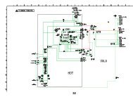
■ Voltage Adjustment1. After replacing the SMPS or PDP panel, you must adjust the voltage referring <strong>to</strong> the voltage label printed on the panel.(If you do not adjust the voltage, an abnormal discharge symp<strong>to</strong>m may appear.)ValueVs 207Va 54Vset -Ve 95Vscan -190Board AdjustmentSMPS2. A point of adjusting SMPS-MAIN voltage.
4-3 Upgrade4-3-1 USB Download Method1. Copy the Upgrade Files in<strong>to</strong> the path "T-CRLAUSC" in USB flash driver.2. USB Download1 Stanby mode2 Enter fac<strong>to</strong>ry mode (INFO→MENU→MUTE→POWER ON)3 Select "CONTROL" from the menu.4 Select "sub option" from the menu.5 Change "usb upgrade" off → on.6 Insert the usb memory stick <strong>to</strong> the service port7 The banner OSD "Upgrade version **** <strong>to</strong> version ****" is displayed.Select "Yes".8 Probably usb memory stick and ir led twinkle slowly.(that means erasing old file) and then they twikle fastly.(start upgrading) after 2minute, au<strong>to</strong>matically turn the poweroff and on.9 On fac<strong>to</strong>ry mode, check the s/w version. select "option"from the menu.10 Select "pdp group" P45A_42SP or P45A_50SP.select "Fac<strong>to</strong>ry Reset" and remove the usb memory stick