experimental heat transfer analysis of the ipr-r1 triga reactor - CDTN
experimental heat transfer analysis of the ipr-r1 triga reactor - CDTN
experimental heat transfer analysis of the ipr-r1 triga reactor - CDTN
- No tags were found...

You also want an ePaper? Increase the reach of your titles
YUMPU automatically turns print PDFs into web optimized ePapers that Google loves.
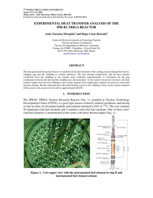
3 rd WORLD TRIGA USERS CONFERENCEAugust 22 to 25, 2006Minascentro – Belo Horizonte, Minas Gerais, BRAZIL.CENTRO DE DESENVOLVIMENTO DA TECNOLOGIA NUCLEAR – <strong>CDTN</strong>/CNENEXPERIMENTAL HEAT TRANSFER ANALYSIS OF THEIPR-R1 TRIGA REACTORAmir Zacarias Mesquita 1 and Hugo César Rezende 2Centro de Desenvolvimento da Tecnologia Nuclea<strong>r1</strong>Serviço de Reator e Irradiações2Serviço de Engenharia de Reatores e SistemasCampus da UFMG - Pampulha – Caixa Postal 94130123-970, Belo Horizonte, MG, Brazil.amir@cdtn.br, hcr@cdtn.brABSTRACTThe <strong>heat</strong> generated by nuclear fission is <strong>transfer</strong>red from fuel elements to <strong>the</strong> cooling system through <strong>the</strong> fuel-tocladdinggap and <strong>the</strong> cladding to coolant interfaces. The fuel <strong>the</strong>rmal conductivity and <strong>the</strong> <strong>heat</strong> <strong>transfer</strong>coefficient from <strong>the</strong> cladding to <strong>the</strong> coolant were evaluated <strong>experimental</strong>ly. A correlation for <strong>the</strong> gapconductance between <strong>the</strong> fuel and <strong>the</strong> cladding was also presented. As <strong>the</strong> <strong>reactor</strong> core power increases, <strong>the</strong> <strong>heat</strong><strong>transfer</strong> regime from <strong>the</strong> fuel cladding to <strong>the</strong> coolant changes from single-phase natural convection to subcoolednucleate boiling. Results indicated that subcooled boiling occurs at <strong>the</strong> cladding surface in <strong>the</strong> central channels<strong>of</strong> <strong>the</strong> <strong>reactor</strong> core at power levels above approximately 60 kW.1. INTRODUCTIONThe IPR-R1 TRIGA Nuclear Research Reactor (Fig. 1), installed at Nuclear TechnologyDevelopment Center (<strong>CDTN</strong>), is a pool type <strong>reactor</strong> cooled by natural circulation, and havingas fuel an alloy <strong>of</strong> zirconium hydride and uranium enriched at 20% in 235 U. The core contains59 aluminum-clad fuel elements and 5 stainless steel-clad fuel elements. One <strong>of</strong> <strong>the</strong>se steelcladfuel elements is instrumented in <strong>the</strong> center with three <strong>the</strong>rmocouples (Fig. 1).Figure 1. Core upper view with <strong>the</strong> instrumented fuel element in ring B andinstrumented fuel element scheme
The <strong>heat</strong> generated by fissions is <strong>transfer</strong>red from fuel elements to <strong>the</strong> cooling system througha fuel-to-cladding interface and from cladding to coolant. The objective <strong>of</strong> <strong>the</strong> <strong>the</strong>rmal andhydrodynamic projects <strong>of</strong> <strong>the</strong> <strong>reactor</strong>s is to remove <strong>the</strong> <strong>heat</strong> safely, without producingexcessive temperature in <strong>the</strong> fuel elements. The regions <strong>of</strong> <strong>the</strong> <strong>reactor</strong> core where boilingoccurs at various power levels can be determined from <strong>the</strong> <strong>heat</strong> <strong>transfer</strong> coefficient data.The <strong>the</strong>rmal conductivity (k) <strong>of</strong> <strong>the</strong> metallic alloys is mainly a function <strong>of</strong> temperature. Innuclear fuels, this relationship is more complicated because k also becomes a function <strong>of</strong>irradiation as a result <strong>of</strong> change in <strong>the</strong> chemical and physical composition (porosity changesdue to temperature and fission products). Many factors affect <strong>the</strong> fuel <strong>the</strong>rmal conductivity.The major factors are temperature, porosity, oxygen to metal atom ratio, PuO 2 content, pelletcracking, and burnup. The second largest resistance to <strong>heat</strong> conduction in <strong>the</strong> fuel rod is dueto <strong>the</strong> gap. Several correlations exist [1] to evaluate its value in power <strong>reactor</strong>s fuels, whichuse mainly uranium oxide. The only reference found to TRIGA <strong>reactor</strong>s fuel is GeneralAtomic [2] that recommends <strong>the</strong> use <strong>of</strong> three hypo<strong>the</strong>ses for <strong>the</strong> <strong>heat</strong> <strong>transfer</strong> coefficient in<strong>the</strong> gap. The <strong>heat</strong> <strong>transfer</strong> coefficient (h) is a property not only <strong>of</strong> <strong>the</strong> system but also dependson <strong>the</strong> fluid properties. The determination <strong>of</strong> h is a complex process that depends on <strong>the</strong><strong>the</strong>rmal conductivity, density, viscosity, velocity, dimensions and specific <strong>heat</strong>. All <strong>the</strong>separameters are temperature-dependent and change when <strong>heat</strong> is being <strong>transfer</strong>red from <strong>the</strong><strong>heat</strong>ed wall to <strong>the</strong> fluid. An operational computer program and a data acquisition and signalprocessing system were developed as part <strong>of</strong> this research project [9] to allow on linemonitoring <strong>of</strong> <strong>the</strong> operational parameters.1. OVERALL THERMAL CONDUCTIVITY OF THE FUEL ELEMENTSFrom Fourier equation described in [5, 6], it was obtained <strong>the</strong> expression <strong>of</strong> overall <strong>the</strong>rmalconductivity (k g ), in [W/mK], for cylindrical fuel elementskg''' 2q r= , (1)4(T −T)owhere q”’ is <strong>the</strong> volumetric rate <strong>of</strong> <strong>heat</strong> generation [W/m 3 ], T o and T sur are <strong>the</strong> fuel centraltemperature and <strong>the</strong> surface temperature [ o C] and r is <strong>the</strong> fuel element radius [m].The temperature at <strong>the</strong> center <strong>of</strong> <strong>the</strong> fuel was measured. The <strong>heat</strong> <strong>transfer</strong> regime at <strong>the</strong> power<strong>of</strong> 265 kW in all fuel elements is <strong>the</strong> subcooled nucleate boiling. The cladding outsidetemperature is <strong>the</strong> water saturation temperature (T sat ) at <strong>the</strong> pressure <strong>of</strong> 1.5 bar (atmosphericpressure added up <strong>of</strong> <strong>the</strong> water column <strong>of</strong> ~ 5.2 m), increased <strong>of</strong> <strong>the</strong> wall super<strong>heat</strong> (T sat ).The superficial temperature (T sur ) in [ o C] is found using <strong>the</strong> expression below, where T sat isequal to 111.37 o C [7].T = T + ∆T. (2)sursatThe wall super<strong>heat</strong> is obtained by using <strong>the</strong> correlation proposed by McAdams found in [8],with q" in [W/m 2 ] and T sat in [ o C].sursat∆ T ′′ , (3)0.259sat= 0.81( q )A fuel element instrumented with three type K <strong>the</strong>rmocouples was introduced into positionB1 as shown in Fig. 1. Two <strong>the</strong>rmocouples were also placed in two core channels adjacent toposition B1.3 rd WORLD TRIGA USERS CONFERENCE – Belo Horizonte, MG, Brazil
Single-Phase Region2. HEAT TRANSFER IN THE REACTOR COREThe <strong>heat</strong> <strong>transfer</strong> coefficient in single-phase region (h sp ) was calculated with <strong>the</strong> Dittus-Boelter correlation described in [10], valid for turbulent flow in narrow channels, given for:hsp= 0.023kDw GDw µ 0.8 cpµ k 0.4, (4)where D w = 4A/P w is <strong>the</strong> hydraulic diameter <strong>of</strong> <strong>the</strong> channel based on <strong>the</strong> wetted perimeter; Ais <strong>the</strong> flow area [m 2 ]; P w is <strong>the</strong> wetted perimeter [m]; G is <strong>the</strong> mass flow [kg/m 2 s]; c p is <strong>the</strong>isobaric specific <strong>heat</strong> [J/kgK]; k is <strong>the</strong> <strong>the</strong>rmal conductivity [W/mK]; and, is <strong>the</strong> fluiddynamic viscosity [kg/ms]. The fluid properties for <strong>the</strong> IPR-R1 TRIGA core are calculatedfor <strong>the</strong> bulk water temperature at 1.5 bar.The two hottest channels in <strong>the</strong> core are Channel 0 and Channel 1' (Fig. 2). The <strong>heat</strong> <strong>transfer</strong>coefficient was estimated using <strong>the</strong> Dittus-Boelter correlation. The inlet and outlettemperatures in Channel 0 were considered as being <strong>the</strong> as in Channel 1'. Table 1 gives <strong>the</strong>geometric data <strong>of</strong> Channel 0 and Channel 1' and <strong>the</strong> percent contribution <strong>of</strong> each fuel elementto <strong>the</strong> channel power. The curves <strong>of</strong> single-phase <strong>heat</strong> <strong>transfer</strong>, as function <strong>of</strong> ∆T sat , arepresented in <strong>the</strong> Fig. 2.Figure 2. The two hottest channels in <strong>the</strong> core and <strong>heat</strong>-<strong>transfer</strong> regimes in <strong>the</strong> fuelelement surfaceThe mass flow rate is given indirectly from <strong>the</strong> <strong>the</strong>rmal balance along <strong>the</strong> channel usingmeasurements <strong>of</strong> <strong>the</strong> water inlet and outlet temperatures:q = mc p∆T, (5)where q is <strong>the</strong> power supplied to <strong>the</strong> channel [kW]; m is <strong>the</strong> mass flow rate in <strong>the</strong> channel[kg/s]; c p is <strong>the</strong> isobaric specific <strong>heat</strong> <strong>of</strong> <strong>the</strong> water [J/kgK]; and, T is <strong>the</strong> temperaturedifference along <strong>the</strong> channel [ o C].3 rd WORLD TRIGA USERS CONFERENCE – Belo Horizonte, MG, Brazil
Table 1. Channel 0 and Channel 1’ Characteristics [9]Channel 0 Channel 1’ UnitArea ( A ) 1.574 8.214 cm 2Wetted Perimeter ( P w ) 5.901 17.643 cmHeated Perimeter ( P h ) 3.906 15.156 cmHydraulic Diameter ( D w ) 1.067 1.862 cmB1 and C1 Fuel Diameter (stainless) 3.76 3.76 cmB6 and C12 Fuel Diameter (Al) 3.73 3.73 cmC1 Control Rod Diameter 3.80 3.80 cmCentral Thimble 3.81 3,81 cmCore Total Power (265 kW) 100 100 %B1 Fuel Contribution 0.54 1.11 %B6 Fuel Contribution 0.46 0.94 %C11 Fuel Contribution - 0.57 %C12 Fuel Contribution - 1.08 %Total Power <strong>of</strong> <strong>the</strong> Channel 1.00 3.70 %The <strong>reactor</strong> was operated on steps <strong>of</strong> about 50 kW until 265 kW and data were collected infunction <strong>of</strong> <strong>the</strong> power supplied to Channel 1' and Channel 0. The values <strong>of</strong> <strong>the</strong> water<strong>the</strong>rmodynamic properties at <strong>the</strong> pressure 1.5 bar as function <strong>of</strong> <strong>the</strong> bulk water temperature at<strong>the</strong> channel were taken from Wagner and Kruse [7]. The curve for <strong>heat</strong> <strong>transfer</strong> coefficient(h sur ) in <strong>the</strong> single-phase region is shown in Fig. 3 as function <strong>of</strong> <strong>the</strong> power.Subcooled Nucleate Boiling RegionFor <strong>the</strong> subcooled nucleated boiling region (local or surface boiling), <strong>the</strong> expression used isshown below, according to [11, 12]:h sur = q” / T sat , (6)where h sur is <strong>the</strong> convective <strong>heat</strong>-<strong>transfer</strong> coefficient from <strong>the</strong> fuel cladding outer surface to<strong>the</strong> water [kW/m 2 K]; q" is <strong>the</strong> fuel surface <strong>heat</strong> flux [kW/m 2 ]; and, T sat is <strong>the</strong> surfacesuper<strong>heat</strong> in contact with <strong>the</strong> water [ o C].Figure 2 presents <strong>the</strong> fuel element surface <strong>heat</strong> <strong>transfer</strong> coefficient for <strong>the</strong> coolant as afunction <strong>of</strong> <strong>the</strong> super<strong>heat</strong>, in both regimes. This curve is specific for <strong>the</strong> IPR-R1 TRIGA<strong>reactor</strong> conditions. The correlation used for <strong>the</strong> subcooled nucleate boiling is not valid forsingle-phase convection region, as well as <strong>the</strong> Dittus-Boelter correlation is not valid for <strong>the</strong>boiling region. The transition point between single-phase convection regime to subcoolednucleate boiling regime (onset <strong>of</strong> nucleate boiling) is approximately 60 kW as shown in <strong>the</strong>graph.Figure 3 presents <strong>the</strong> curves for <strong>the</strong> <strong>heat</strong> <strong>transfer</strong> coefficient (h sur ) on <strong>the</strong> fuel element surfaceand for <strong>the</strong> overall <strong>the</strong>rmal conductivity (k g ) in fuel element as function <strong>of</strong> <strong>the</strong> power,obtained for <strong>the</strong> instrumented fuel at core position B1.3 rd WORLD TRIGA USERS CONFERENCE – Belo Horizonte, MG, Brazil
Figure 3. Overall fuel element <strong>the</strong>rmal conductivity and cladding <strong>heat</strong> <strong>transfer</strong>coefficient to <strong>the</strong> coolant3. HEAT TRANSFER COEFFICIENT IN THE FUEL GAPThe instrumented fuel element is composed <strong>of</strong> a central zirconium filler rod with 6.25 mm indiameter, <strong>the</strong> active part <strong>of</strong> <strong>the</strong> fuel, formed by uranium zirconium hydride alloy (U-ZrH 1.6 ),an interface (gap) between <strong>the</strong> fuel and <strong>the</strong> cladding, and <strong>the</strong> 304 stainless steel cladding. The<strong>the</strong>rmocouples are fixed in <strong>the</strong> central rod. It is assumed that all <strong>heat</strong> flux is in <strong>the</strong> radialdirection. Using <strong>the</strong> analogy with electric circuits, <strong>the</strong> resistance to <strong>the</strong> <strong>heat</strong> conduction from<strong>the</strong> fuel center to <strong>the</strong> coolant (R g ) is given by <strong>the</strong> sum <strong>of</strong> <strong>the</strong> fuel components resistances.The fuel element configuration is shown in Fig. 4. The axial <strong>heat</strong> conduction and <strong>the</strong> presence<strong>of</strong> <strong>the</strong> central pin <strong>of</strong> zirconium were not considered. The <strong>the</strong>rmal conductivity <strong>of</strong> <strong>the</strong> U-ZrH 1.6fuel is given by [13]:k UZrH = 0.0075 T + 17.58, (7)with T in [ o C] and k UZrH in [W/mK]. The <strong>the</strong>rmal conductivity <strong>of</strong> <strong>the</strong> AISI 304 steel claddingis given by [14]:with T in [ o C] and k rev in [W/mK].k rev = 3.17x 10 -9 T 3 -6.67 x 10 -6 T 2 +1.81 x10 -2 T+14.46, (8)The value <strong>of</strong> R gap is <strong>the</strong> value <strong>of</strong> <strong>the</strong> overall resistance <strong>of</strong> <strong>the</strong> fuel element (R g ) less <strong>the</strong> values<strong>of</strong> o<strong>the</strong>r component resistance. It is found with <strong>the</strong> values <strong>of</strong> k g and h sur obtained previouslyand with <strong>the</strong> values <strong>of</strong> k for <strong>the</strong> fuel alloy and for <strong>the</strong> cladding corrected in function <strong>of</strong>temperature. The <strong>heat</strong> <strong>transfer</strong> coefficient in <strong>the</strong> gap is:hgap=2 r0 kUZrHkrevgk− k kgkrevUZrHkrev− 2k kgUZrHn( r ) 2/ <strong>r1</strong>(9)3 rd WORLD TRIGA USERS CONFERENCE – Belo Horizonte, MG, Brazil
The graph <strong>of</strong> <strong>heat</strong> <strong>transfer</strong> coefficient through <strong>the</strong> gap is shown in Fig. 4, as a function <strong>of</strong> <strong>the</strong><strong>reactor</strong> power. This figure also shows three <strong>the</strong>oretical values recommended by GeneralAtomic for <strong>the</strong> <strong>heat</strong> <strong>transfer</strong> coefficient [2].Figure 4. Heat <strong>transfer</strong> coefficient through <strong>the</strong> gap as a function <strong>of</strong> <strong>the</strong> power and fuelelement configuration4. FUEL ROD TEMPERATURE PROFILEFrom <strong>the</strong> temperature in <strong>the</strong> center <strong>of</strong> <strong>the</strong> fuel and using <strong>the</strong> equations <strong>of</strong> conduction for <strong>the</strong>fuel element geometry, it is possible to obtain <strong>the</strong> radial temperature distribution in <strong>the</strong> fuelelement. Figure 5 shows <strong>the</strong> <strong>experimental</strong> radial pr<strong>of</strong>ile <strong>of</strong> maximum fuel temperature inposition B1 and it is compared with <strong>the</strong> PANTERA code results [15]. The instrumented fuelelement was used to measure <strong>the</strong> fuel temperature at several <strong>reactor</strong> powers. The results arealso shown in Fig. 5.Figure 5. Experimental fuel rod radial temperature pr<strong>of</strong>ile in position B1 at 265 kWand at o<strong>the</strong>r <strong>reactor</strong> powers5. CONCLUSIONSubcooled pool boiling occurs above approximately 60 kW on <strong>the</strong> cladding surface in <strong>the</strong>central channels <strong>of</strong> <strong>the</strong> IPR-R1 TRIGA core. However, <strong>the</strong> high <strong>heat</strong> <strong>transfer</strong> coefficient dueto subcooled boiling causes <strong>the</strong> cladding temperature be quite uniform along most <strong>of</strong> <strong>the</strong>active fuel rod region and do not increase very much with <strong>the</strong> <strong>reactor</strong> power. The IPR-R13 rd WORLD TRIGA USERS CONFERENCE – Belo Horizonte, MG, Brazil
TRIGA Reactor normally operates in <strong>the</strong> range from 100 kW until a maximum <strong>of</strong> 250 kW.On <strong>the</strong>se power levels <strong>the</strong> <strong>heat</strong> <strong>transfer</strong> regime between <strong>the</strong> clad surface and <strong>the</strong> coolant issubcooled nucleate boiling in <strong>the</strong> hottest fuel element. Boiling <strong>heat</strong> <strong>transfer</strong> is usually <strong>the</strong>most efficient <strong>heat</strong> <strong>transfer</strong> pattern in nuclear <strong>reactor</strong>s core [6]. Ano<strong>the</strong>r important aspect <strong>of</strong><strong>the</strong> <strong>reactor</strong> operation safety is that it is far from <strong>the</strong> occurrence <strong>of</strong> critical <strong>heat</strong> flux [16].ACKNOWLEDGMENTSThe authors thank to <strong>the</strong> operation staff <strong>of</strong> <strong>the</strong> IPR-R1 TRIGA Reactor for <strong>the</strong>ir help during<strong>the</strong> experiments.REFERENCES1. Todreas N.E. and Kazimi M.S., Nuclear Systems I: Thermal Hydraulic Fundaments,Hemisphere Publishing Corporation, New York, (1990).2. General Atomic, Safeguards Summary Report for <strong>the</strong> New York University TRIGA MarkI Reactor. (GA-9864). San Diego, (1970).3 Dalle H.M., Neutronic Calculations <strong>of</strong> <strong>the</strong> IPR-R1 TRIGA Reactor with WIMSD4 eCITATION. M. Sc dissertation, Universidade Federal de Minas Gerais, Belo Horizonte,(in Portuguese), (1999).4 Dalle H.M., Neutronic Analyses <strong>of</strong> <strong>the</strong> IPR-R1 TRIGA Reactor with 63 Fuel ElementsConfiguration and Regulating Control Rod in Position F16, <strong>CDTN</strong>/CNEN, NI–EC3-01/03, Belo Horizonte, (in Portuguese), (2003).5 Lamarsh J.R. and Baratta A.J., Introduction to Nuclear Engineering, 3° ed., UpperSaddler River: Prendice Hall, (2001).6 Duderstadt J.J and Hamilton L.J.; Nuclear Reactor Analysis, John Wiley & Sons, Inc.New York, (1976).7. Wagner W. and Kruse A., Properties <strong>of</strong> Water and Steam – The Industrial StandardIAPWS-IF97 for <strong>the</strong> Thermodynamics Properties, Springer, Berlin, (1998).8. Tong L.S. and Weisman J., Thermal Analysis <strong>of</strong> Pressurized Water Reactors, ThirdEdition, American Nuclear Society. Illinois, (1996)9. Mesquita A. Z., Experimental Investigation on Temperatures Distributions in a ResearchNuclear Reactor TRIGA IPR-R1, Ph.D <strong>the</strong>sis, Universidade Estadual de Campinas, SãoPaulo, (in Portuguese), (2005).10. Glasstone S. and Sesonske A., Nuclear Reactor Engineering, 4 ed., Chapman and Hall,New York, NY, (1994).11. Kreith F. and Bohn M. S., Principles <strong>of</strong> Heat Transfer, 6 th ed., Brooks/Cole, New York,(2001).12. Tong L. S. and Tang Y.S, Boiling Heat Transfer and Two-Phase Flow, 2 nd . Ed. Taylor &Francis, Washington, (1997).13. Simnad M.T., Foushee F.C. and West G.B., Fuel Elements for Pulsed TRIGA ResearchReactors, Nuclear Technology, 28:31-56. (1976).14. ASME, ASME Boiler and Pressure Vessel Code, Section II − Materials, Part D,Properties”, The American Society <strong>of</strong> Mechanical Engineers, New York, (1992).15. Veloso M.A., Thermal–hydraulic Analyses <strong>of</strong> <strong>the</strong> IPR-R1 TRIGA Reactor on 250 kW,<strong>CDTN</strong>/CNEN, NI-EC3-05/05, Belo Horizonte, (in Portuguese), (2005).16. Mesquita A.Z. and Rezende H.C., Experimental Prediction <strong>of</strong> <strong>the</strong> Critical Heat Flux on<strong>the</strong> IPR-R1 TRIGA Nuclear Reactor. Proceeding <strong>of</strong> 3 nd World Triga Users Conference,Belo Horizonte, August 22 to 25, (2006).3 rd WORLD TRIGA USERS CONFERENCE – Belo Horizonte, MG, Brazil