21DQ10 SCHOTTKY BARRIER DIODE PRV : 100 Volts Io - EIC
21DQ10 SCHOTTKY BARRIER DIODE PRV : 100 Volts Io - EIC
21DQ10 SCHOTTKY BARRIER DIODE PRV : 100 Volts Io - EIC

You also want an ePaper? Increase the reach of your titles
YUMPU automatically turns print PDFs into web optimized ePapers that Google loves.
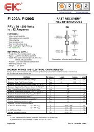
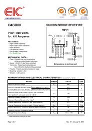
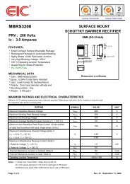
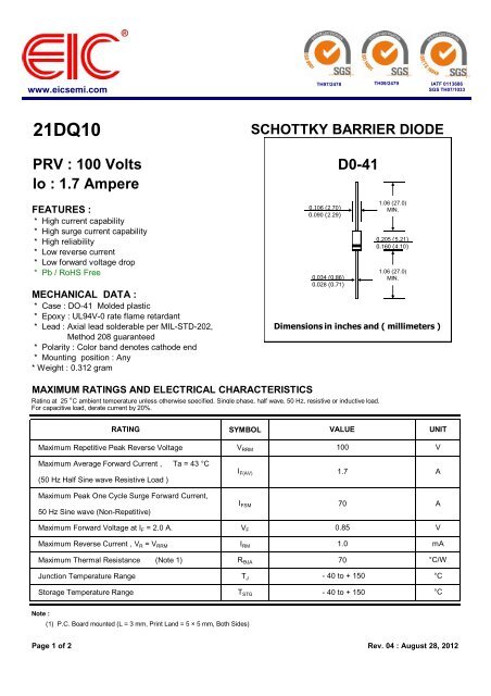
www.eicsemi.comTH97/2478TH09/2479IATF 0113686SGS TH07/1033<strong>21DQ10</strong> <strong>SCHOTTKY</strong> <strong>BARRIER</strong> <strong>DIODE</strong><strong>PRV</strong> : <strong>100</strong> <strong>Volts</strong><strong>Io</strong> : 1.7 AmpereFEATURES :* High current capability* High surge current capability* High reliability* Low reverse current* Low forward voltage drop* Pb / RoHS FreeMECHANICAL DATA :* Case : DO-41 Molded plastic* Epoxy : UL94V-0 rate flame retardant* Lead : Axial lead solderable per MIL-STD-202,Method 208 guaranteed* Polarity : Color band denotes cathode end* Mounting position : Any* Weight : 0.312 gram0.106 (2.70)0.090 (2.29)0.034 (0.86)0.028 (0.71)D0-411.06 (27.0)MIN.0.205 (5.21)0.160 (4.10)1.06 (27.0)MIN.Dimensions in inches and ( millimeters )MAXIMUM RATINGS AND ELECTRICAL CHARACTERISTICSRating at 25 °C ambient temperature unless otherwise specified. Single phase, half wave, 50 Hz, resistive or inductive load.For capacitive load, derate current by 20%.RATINGSYMBOLVALUEUNITMaximum Repetitive Peak Reverse VoltageV RRM<strong>100</strong>VMaximum Average Forward Current , Ta = 43 °C(50 Hz Half Sine wave Resistive Load )I F(AV)1.7AMaximum Peak One Cycle Surge Forward Current,50 Hz Sine wave (Non-Repetitive)I FSM70AMaximum Forward Voltage at I F = 2.0 A.V F0.85VMaximum Reverse Current , V R = V RRMI RM1.0mAMaximum Thermal Resistance (Note 1) R ӨJA 70°C/WJunction Temperature RangeT J- 40 to + 150°CStorage Temperature Range T STG - 40 to + 150°CNote :(1) P.C. Board mounted (L = 3 mm, Print Land = 5 × 5 mm, Both Sides)Page 1 of 2 Rev. 04 : August 28, 2012
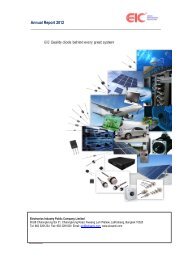
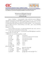
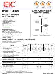
www.eicsemi.comTH97/2478TH09/2479IATF 0113686SGS TH07/1033RATING AND CHARACTERISTIC CURVES ( <strong>21DQ10</strong> )AVERAGE FORWARD OUTPUTCURRENT, AMPERES3.02.52.01.51.00.50FIG.1 - AVERAGE FORWARD CURRENT VS.DCFIG.2 - MAXIMUM NON-REPETITIVE PEAKAMBIENT TEMPERATURE FORWARD SURGE CURRENTHALF SINE WAVE0 25 50 75 <strong>100</strong> 125 150 175AMBIENT TEMPERATURE, ( °C)PEAK FORWARD SURGECURRENT, AMPERES80706050403020<strong>100</strong>0.02sI FSMf = 50Hz, Half sine wave,No load0.02 0.05 0.1 0.2 0.5 1 2TIME (s)INSTANTANEOUS FORWARD CURRENT,AMPERESFIG. 3 - FORWARD CURRENT VS. FOREARD VOLTAGE105.02.01.00.50.2T J = 150°CT J = 25°C0.10 0.2 0.4 0.6 0.8 1.0 1.2INSTANTANEOUS FORWARD VOLTAGE, VOLTSJUNCTION CAPACITANCE, pFFIG. 4 – JUNCTION CAPACITANCE VS.REVERSE VOLTAGE200<strong>100</strong>5020<strong>100</strong>.5 1 2 5 10 20 50 <strong>100</strong> 200REVERSE VOLTAGE, VOLTSPage 2 of 2 Rev. 04 : August 28, 2012