Irrigation System Planning and Installation Guide - Philmac
Irrigation System Planning and Installation Guide - Philmac
Irrigation System Planning and Installation Guide - Philmac

Create successful ePaper yourself
Turn your PDF publications into a flip-book with our unique Google optimized e-Paper software.
Fig. M. Punch the hole<br />
with a PK4 Punch/Spanner<br />
<strong>Irrigation</strong> equipment available from:<br />
<strong>Irrigation</strong><br />
<strong>System</strong><br />
<strong>Planning</strong><br />
<strong>and</strong><br />
<strong>Installation</strong><br />
<strong>Guide</strong>
1 Introduction<br />
Thank you for considering a precision irrigation system for your l<strong>and</strong>scape.<br />
A precision irrigation system will reduce your watering costs, provide you<br />
more freedom <strong>and</strong> keep your l<strong>and</strong>scape healthy all year round. This<br />
planning guide will assist you with the design <strong>and</strong> installation of a fully<br />
automatic irrigation system using quality <strong>Philmac</strong> <strong>and</strong> Hunter products.<br />
We recommend you also seek advice from a professional irrigation outlet<br />
where you will also be able to obtain the latest specification sheets.<br />
2 Measure <strong>and</strong> Plan<br />
Measure all the areas you plan to water as well as major structures such<br />
as your house, pergola, driveway, shed etc. Place these details on the<br />
graph overleaf <strong>and</strong> mark your scale e.g. 1 cm = 1 metre or 1 cm = 2<br />
metres. Also mark your water sources such as taps or where a licensed<br />
plumber can tap into a mainline <strong>and</strong> install an isolating valve <strong>and</strong><br />
backflow device. <strong>Philmac</strong> do not recommend operating sprinkler systems<br />
from garden taps.<br />
3 Measure the Water Source<br />
Fig. A. Bucket test<br />
To determine how many sprinklers, spray<br />
jets or drippers can be operated you first<br />
need to undertake a flow test. For spray<br />
jets <strong>and</strong> drippers this can be done by using<br />
a 9 litre bucket (see Fig. A). From the<br />
tap/outlet location you plan to use, time<br />
how long it takes to fill a 9 litre bucket<br />
with the tap fully open. Remember to<br />
ensure all other taps/outlets are turned<br />
off <strong>and</strong> undertake the test as close as<br />
possible to the time you plan to water.<br />
Flows will vary over a 24 hour period.<br />
To determine how many litres per hour<br />
are available, apply the following formula<br />
or use the table below:<br />
Litres per hour = 9 x 3600<br />
Time to fill bucket (in seconds)<br />
e.g. 9 x 3600<br />
15 sec<br />
= 2,160 litres per hour (L/h)<br />
Now deduct 20% from the result to allow for the systems operating<br />
pressure <strong>and</strong> seasonal fluctuations. This gives a nett flow rate of 1,728 L/h.<br />
If other taps or outlets are to be used then they need to be measured<br />
as well. For sprinklers, it is essential a “Flow/Pressure Test Kit” is used.<br />
Talk to your <strong>Irrigation</strong> Specialist about this.<br />
Litres per Hour - Using a 9 Litre Bucket<br />
Time Litres/ Time Litres/ Time Litres/<br />
Taken Hour Taken Hour Taken Hour<br />
7 sec 3,702 11 sec 2,356 18 sec 1,440<br />
8 sec 3,240 12 sec 2,160 20 sec 1,296<br />
9 sec 2,880 14 sec 1,851 22 sec 1,178<br />
10 sec 2,592 16 sec 1,620 24 sec 1,080<br />
4 Selecting the Emitters<br />
There are a number of emitters available to water plants with, including<br />
drippers, jets, fixed sprays, pop-up sprays <strong>and</strong> rotors (gear drives). Ideally<br />
different emitter types should not be installed on the same section. For<br />
example drippers have an optimal operating pressure around 100 kPa<br />
(see Glossary) <strong>and</strong> may need to be operated for several hours to deliver<br />
sufficient water. Compare this to pop-up sprays which have an optimal<br />
operating pressure around 200 kPa <strong>and</strong> may only require operating for<br />
10-20 minutes. Even emitters which operate at the same pressure can<br />
have quite different flow rates e.g. drippers versus jets.<br />
2<br />
4.1 Drippers<br />
<strong>Philmac</strong> drippers with barbed inlets are available in fixed discharge<br />
(2, 4 & 8 L/h) <strong>and</strong> fixed pressure compensating discharge (2 & 4 L/h)<br />
(see Fig. B). They are also available in adjustable discharge (0-100 L/h)<br />
with barbed inlets, on spikes <strong>and</strong> with 1 /2” BSP thread. The ideal<br />
operating pressure is around 100 -150 kPa.<br />
Drippers provide a concentrated wetting pattern <strong>and</strong> are well suited where:<br />
• water is limited<br />
• soils are “heavy” <strong>and</strong> runoff occurs with sprinklers<br />
• it is important not to wet foliage<br />
• evaporation needs to be limited<br />
Fig. B. <strong>Philmac</strong> drippers.<br />
4.2 Jets <strong>and</strong> Spray Jets<br />
<strong>Philmac</strong> jets <strong>and</strong> sprays feature threaded bases which allows them to screw<br />
into flexible 4mm tube or onto rigid risers. Sprays <strong>and</strong> Jets are normally<br />
used to water garden beds <strong>and</strong> for shadehouse/greenhouse applications<br />
(see Fig. C). They are available in a range of flow rates <strong>and</strong> patterns:<br />
XL-Jet (Garden Series) – Combines penetrating streams with a feather<br />
pattern in 360º, 180º <strong>and</strong> 90º.<br />
XL-Jet (Specialty Series) – Strip sprays for elongated areas <strong>and</strong> a mister<br />
for shadehouses/greenhouses.<br />
Spray Jets (One Piece) – Provide a fan pattern in 360º, 180º <strong>and</strong> 90º<br />
<strong>and</strong> available with 55L/h or 90L/h flow rates.<br />
Spray Jets (Two Piece) – Provide a variety of patterns <strong>and</strong> flow rates.<br />
Micro-Sprinklers – Have a frame <strong>and</strong> nozzle with a flipper (rotor) which<br />
throws water further distances than jets in a variety of flow rates. They<br />
are available as anti-ant versions such as Orbitor <strong>and</strong> StreamMaster or as<br />
a st<strong>and</strong>ard version such as the Challenger.<br />
Fig. C. A fixed spray <strong>and</strong> a micro- sprinkler<br />
4.3 Pop-Up Sprays<br />
Pop-up sprays (see Fig. D.) are typically used to<br />
water small lawned areas. 100mm (4”) is the<br />
most common pop height used as it readily<br />
pops above the height of the lawn (50mm,<br />
150mm <strong>and</strong> 300mm are also available).<br />
Some models such as the Hunter PS Series have<br />
the nozzle built in while others such as the<br />
Hunter Pro-Spray <strong>and</strong> Institutional Spray have the<br />
ability to fit a wide range of threaded female<br />
nozzles. Nozzles typically have a radius of 2.1m,<br />
3m, 3.6m, 4.6m or 5.2m. They are available in<br />
adjustable arc, fixed arc <strong>and</strong> specialty patterns<br />
such as side strips <strong>and</strong> centre strips.<br />
Fig. D. A pop-up spray<br />
Sprays can also be used to water garden beds as they have 300mm (12”)<br />
pop heights available which can water “over” plants. They also have the<br />
advantage that they retract out of sight when not in use <strong>and</strong> are less<br />
likely to be eaten by the family dog than rigid risers.<br />
For best performance sprays should be installed head to head. If the radius<br />
is say 3 metres, then the next sprinkler head should be 3 metres away.
4.4 Pop-up Rotors (Gear Drives)<br />
For larger lawned areas (4.6m radius <strong>and</strong> above)<br />
rotors are the ideal choice as they can provide<br />
even watering combined with low application<br />
rates (see Glossary). Like sprays they pop-up, but<br />
rather than spray a wide area at one time they<br />
have a stream of water (see Fig. E) which moves<br />
in an adjustable arc over the area to be watered.<br />
This arc can normally be adjusted between 40º<br />
<strong>and</strong> 360º.<br />
Hunter rotors are supplied with nozzle racks which<br />
have a range of flow rates <strong>and</strong> radius of throw.<br />
This allows the optimum performance to be achieved.<br />
5 Designing the <strong>System</strong><br />
A system design is based on having an automatic controller which<br />
operates electric solenoid valves. The valves in turn operate the emitters.<br />
Once you have decided what types of emitters to use in different parts of<br />
your garden it is time to start plotting where you would like to install<br />
them. It is best to start by dividing the garden into areas that are similar<br />
such as lawns <strong>and</strong> garden beds. Remember to refer back to your flow<br />
test <strong>and</strong> to technical data on performance to get the best spacings.<br />
Emitters will vary in performance depending on the pressure <strong>and</strong> some<br />
depending on whether they are installed at 90º, 180º or 360º. There is<br />
no point spacing sprays at 4m only to find there is only sufficient<br />
pressure to work properly on a 3.5m spacing.<br />
Once all the emitters are plotted then it is time to work out the number<br />
of sections required to water each area. To do this work out the total<br />
flow in the area <strong>and</strong> divide by the nett flow calculated in section 3.<br />
eg Total Flow of Emitters = 3,980L/h = 2.3<br />
Available Flow 1,728L/h<br />
In this case we will need to divide the lawn into 3 sections or we will exceed<br />
the available nett flow. Each section will be controlled by a separate valve.<br />
Once you have divided the emitters into roughly three equal sections we<br />
can determine the flow rate per section. It is then easy to select the size<br />
of low density polyethylene (LDPE) pipe required to obtain the right flow<br />
rate. If pipes are too small there will be a pressure loss <strong>and</strong> the emitters<br />
may not operate correctly. The following table shows the maximum<br />
recommended flow rates for common sizes of LDPE pipe. It assumes the<br />
ground is flat.<br />
LDPE pipe size Flow L/h Flow L/min<br />
13mm (1/2”) 540 9<br />
19mm (3/4”) 1,440 24<br />
25mm (1”) 3,240 54<br />
32mm (1 1 /4”) 4,920 82<br />
All the pipework for each separate section will be connected to a<br />
solenoid valve. In the above example we would require three solenoid<br />
valves to control the water to the lawn. Normally these are manifolded in<br />
a valve box (see Fig. G).<br />
6 Automatic Controls<br />
Fig. E. A rotor<br />
<strong>Philmac</strong> recommends all systems are fully automated as it means watering<br />
can take place when you are on holidays. It is also easier to water within<br />
any time windows determined by local water regulations or restrictions.<br />
6.1 Controllers<br />
The purpose of an irrigation controller is to operate each of our sections<br />
via an electric solenoid valve. The number of sections to be watered will<br />
determine the size of the controller. St<strong>and</strong>ard controllers like the Hunter<br />
EC601A are 6 station, with each station being able to operate a valve.<br />
For larger gardens, controllers like the Hunter Pro-C can be used which<br />
have up to 15 stations (see Fig. F).<br />
Each station can be programmed for start time <strong>and</strong> run time <strong>and</strong> Hunter<br />
controllers have 3 programs so the lawn, garden beds <strong>and</strong> shadehouse can<br />
all be treated differently. Your professional irrigation outlet can give you<br />
more information on the features <strong>and</strong> benefits of irrigation controllers.<br />
3<br />
Fig. F. Pro-C Controller<br />
Where 240V AC power is not available or where it would be difficult to<br />
connect valves to the controller then the Hunter one or four station SVC<br />
battery operated controllers are available.<br />
6.2 Valves<br />
Electric solenoid valves are linked to the irrigation controller via electrical<br />
cable (your irrigation professional can advise on size <strong>and</strong> installation). In a<br />
typical installation valves are manifolded together in a valve box. Valves<br />
normally have a 1” BSP inlet which is connected to high pressure pipe<br />
such as Medium Density Polyethylene (MDPE) or PVC. Whatever is used<br />
must comply with all regulations. The outlet is also normally 1” BSP <strong>and</strong><br />
either 13mm, 19mm or 25mm directors can be screwed into here so<br />
LDPE pipe can be attached (see Fig. G).<br />
When the controller sends a 24V current the valve opens <strong>and</strong> when the<br />
current stops the valve closes. As valves are normally connected into<br />
a potable water source, <strong>Philmac</strong> recommends this is done by a licensed<br />
tradesperson <strong>and</strong> all regulations are adhered to. This may include the<br />
fitting of WaterMark approved isolation valve such as the <strong>Philmac</strong> “Blue<br />
H<strong>and</strong>led” valve (see Fig. G) <strong>and</strong> a backflow prevention device.<br />
Isolating Valve<br />
Director<br />
Fig. G. Valve Box <strong>and</strong> Valve Manifold<br />
6.3 Sensors<br />
Good quality controllers like<br />
the Hunter range have been<br />
designed so that sensors such<br />
as rain sensors can be wired<br />
to them. Rain sensors are<br />
invaluable because they shut<br />
the system down when it is<br />
raining <strong>and</strong> prevent watering<br />
from occurring thus saving<br />
precious water. Hunter also<br />
offer a wireless rain sensor<br />
which makes it extremely easy<br />
to install the sensor in the<br />
correct position. (see Fig. J).<br />
Fig. J. Wireless RainClik sensor<br />
Manifold<br />
Valve Box<br />
Solenoid Valve<br />
LDPE Pipe
7 Installing the <strong>System</strong><br />
7.1 Tools Required<br />
Normally the following tools are required for installation of a system:<br />
• Spade • Trenching shovel • Tape measure<br />
• String line • Secateurs • Multi grips<br />
• Wire cutters • LDPE cutter or secateurs • Ldpe punch<br />
7.2 Preparation<br />
Where possible all fittings should be pre-assembled. For example,<br />
directors into valves <strong>and</strong> threaded tees <strong>and</strong> elbows into sprays or rotors.<br />
When using threaded fittings you must use thread tape to ensure a<br />
watertight seal. If nozzles are to be fitted to sprays or jets to risers they<br />
should not be installed until the system is flushed.<br />
Before beginning any trenching clearly mark where the emitters are to be<br />
located <strong>and</strong> use string lines to indicate where trenches are to be located.<br />
7.3 Trenching<br />
Before digging <strong>Philmac</strong> recommend you check the appropriate authorities<br />
for any buried services such as telephone, power, water <strong>and</strong> gas.<br />
If trenching into existing lawn, the sods of lawn can be put aside <strong>and</strong><br />
replaced later. The depth of the trench can be gauged by using the spray<br />
pop or rotor assembly.<br />
If access is required under pathways or driveways it should be possible<br />
to use a piece of PVC or galvanised pipe with an angle cut on one end.<br />
A trench should be dug on either side then the angled end can be<br />
rammed <strong>and</strong> turned to progressively create a tunnel. It may be necessary<br />
to place a hose inside the pipe <strong>and</strong> have water assist in the process by<br />
softening the soil. The hose should only just be running.<br />
Once the trench is dug the LDPE pipe can be laid (Fig. K), the sprinklers<br />
fitted <strong>and</strong> placed at the correct height <strong>and</strong> the trench backfilled. Care<br />
should be taken that sharp rocks are not placed back in the trench or<br />
they may rub on the LDPE pipe <strong>and</strong> cause holes over time. If necessary<br />
s<strong>and</strong> can be used around the pipe for protection. It may be advisable to<br />
pressure test the system for leaks before filling in the trench.<br />
Fig. K. Digging the trench <strong>and</strong> laying the pipework<br />
7.4 Connections<br />
When using LDPE pipe all connections are done with barbed fittings.<br />
<strong>Philmac</strong> fittings are manufactured from nylon to ensure they have a<br />
sharp barb which bites into the pipe <strong>and</strong> prevents it from coming apart.<br />
It is still important that ratchet clips are used each time a piece of pipe is<br />
attached (see Figure L). All cuts of the LDPE pipe should be made square<br />
to unsure they fit over the barb <strong>and</strong> a clip can be fitted.<br />
When fitting 4mm barbed fittings directly into LDPE pipe it is important to<br />
use a punch like the <strong>Philmac</strong> PK4 to get the right size hole (see Figure N).<br />
Customer Name ......................................................................<br />
Address ..................................................................................<br />
................................................................................................<br />
Phone ........................................ Date ..................................<br />
4<br />
LDPE Pipe<br />
Threaded Tee<br />
Fig. L. Sprinkler connections<br />
Ratchet Clip<br />
Pop-up Spray<br />
Fig. M.<br />
PK4 Punch/Spanner<br />
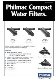
7.5 Filtration<br />
Filtration is most useful when a water source such as a bore or dam is<br />
being used. Threaded filters (see inside page) from 1” to 2” can be<br />
installed after the pump to collect debris that would otherwise block<br />
emitters. When drippers <strong>and</strong> small jets are being used it is wise to use a<br />
filter which has a 130 micron (0.13mm) screen or disc cartridge to filter out<br />
the debris. The cartridges can be removed from the filter for cleaning <strong>and</strong><br />
cleaning will depend on how dirty the water is <strong>and</strong> how often watering<br />
takes place. For sprinklers a 200 micron (0.2mm) cartridge is suitable.<br />
Where water is from a potable water supply, filtration is usually unnecessary<br />
although it is still good practice to use an inline barbed filter as a precaution<br />
such as the one shown on the inside pages. They are available with 13mm,<br />
19mm <strong>and</strong> 25mm barbs. These are installed after the valves.<br />
Glossary of Terms<br />
kPa (kiloPascals) = A measure of pressure. It can be determined using<br />
a gauge. The lower the number, the lower the pressure.<br />
L (litres) = A volume of water.<br />
m (metres) = A measure of distance.<br />
min (minutes) = A measure of time.<br />
BSP (British St<strong>and</strong>ard Pipe) = St<strong>and</strong>ard type of pipe thread used<br />
in Australia.<br />
rad (radius) = A measure (normally in metres) of how far a sprinkler<br />
throws water.<br />
V (Volts) = An electrical measurement.<br />
AC (alternating current) = A type of electrical current.<br />
DC (direct current) = A type of electrical current.<br />
Nozzles = Fitted to the top of spray pops they determine the pattern<br />
<strong>and</strong> radius of throw.<br />
Check Valves = Fitted to the bottom of sprays <strong>and</strong> rotors to prevent<br />
puddling of water.<br />
Micron = A measure of size. One micron is 0.001mm.<br />
Emitter = A device that emits water such as a dripper, spray, pop etc.<br />
Pressure Compensating = An emitter which has approximately the<br />
same output of water over a range of pressures.<br />
Application Rate (mm/h) = The millimetres of water applied per hour.<br />
Calculated by dividing the total volume of water (in litres) applied by the<br />
sprinklers in an hour divided by the area they water (in square metres).<br />
Useful Equations<br />
1 m head = 9.8 kPa<br />
1 bar = 98 kPa<br />
1 psi = 6.9 kPa<br />
1 m3 = 1,000 L = 1 kL<br />
This publication is produced as a guide only <strong>and</strong> while every care has been taken<br />
in compilation, regulations may vary in different areas. We suggest you contact<br />
your local authority to check local requirements. It is also recognised that no<br />
single planning guide can be absolutely comprehensive. A number of Water<br />
Authorities or Water Boards have excellent publications on irrigation. The reader<br />
is encouraged to make use of this information. COPYRIGHT © FEBRUARY 2005.<br />
IS-015B/2-05
C<br />
W<br />
LEGEND:<br />
Controller Valve (Manual) Spray (Micro)<br />
Water Source Rotor Dripper<br />
Valve (Auto) Spray Pop Pipe
C<br />
W<br />
LEGEND:<br />
Controller Valve (Manual) Spray (Micro)<br />
Water Source Rotor Dripper<br />
Valve (Auto) Spray Pop Pipe
<strong>Philmac</strong> Metric Compression Fittings<br />
– Suitable for medium density polyethylene pipe, with PN 12.5 <strong>and</strong> PN 16 pressure ratings.<br />
Available in 20mm to 110mm size.<br />
SPRAY JETS<br />
JSF12 360º Green 55 L/h<br />
JSH12 180º Green 55 L/h<br />
JSQ12 90º Green 55 L/h<br />
JSF16 360º Black 90 L/h<br />
JSH16 180º Black 90 L/h<br />
JSQ16 90º Black 90 L/h<br />
REDUCING TEE<br />
3412RT 19x13mm<br />
1034RT 25x13mm<br />
THREADED MALE TEE<br />
T34G12M 19mm x 1 /2”BSP<br />
T10G12M 25mm x 1 /2”BSP<br />
T10G34M 25mm x 3 /4”BSP<br />
NIPPLES<br />
90421100 1 /2”<br />
90422200 3 /4”<br />
90423100 1”<br />
TEES (FI)<br />
90451100 1 /2”BSP<br />
90452200 3 /4”BSP<br />
90453300 1”BSP<br />
REDUCING JOINER<br />
RJ3412 19x13mm<br />
RJ1012 25x13mm<br />
RJ1034 25x19mm<br />
XL JETS<br />
SF3617 360º - 140 L/h<br />
SF1822 180º - 70 L/h<br />
SF9009 90º - 35 L/h<br />
BALL VALVES<br />
95500100 1 /2”<br />
95500200 3 /4”<br />
95500300 1”<br />
TEE<br />
T12 13mm<br />
T34 19mm<br />
T10 25mm<br />
THREADED MALE ELBOW<br />
E12G12M 13mm x 1 /2”BSP<br />
E34G12M 19mm x 1 /2”BSP<br />
E10G12M 25mm x 1 /2”BSP<br />
E10G34M 25mm x 3 /4”BSP<br />
3CJ Corner 19mm x 1 /2”BSP<br />
SOCKETS<br />
90431100 1 /2”BSP<br />
90432100 3 /4”x 1 /2”BSP<br />
90432200 3 /4”BSP<br />
90433100 1”x 1 /2”BSP<br />
90433200 1”x 3 /4”BSP<br />
90431100 1”BSP<br />
ADJUSTABLE DRIPPERS<br />
OCTA-8 Octa-mitter 0-70 L/h<br />
SD4 Selectaflo 0-100 L/h<br />
S360S Shrubbler® spike 0-33 L/h<br />
S360ST Shrubbler® 1 /2”BSP<br />
MB360S Mini Bubbler® spike<br />
MB360TH Mini Bubbler® 1 /2”BSP<br />
ELBOW<br />
E12 13mm<br />
E34 19mm<br />
E10 25mm<br />
FEMALE THREADED TEE<br />
T34G12F 19mm x 1 /2”BSP<br />
T10G12F 25mm x 1 /2”BSP<br />
T10G34F 25mm x 3 /4”BSP<br />
IN-LINE FILTERS<br />
1-IS-12BB 13mm Tails<br />
1-IS-34BB 19mm Tails<br />
1-IS-10BB 25mm Tails<br />
ELBOWS (MI x FI)<br />
90469100 1 /2”BSP<br />
90469200 3 /4”BSP<br />
90469300 1”BSP<br />
JOINER<br />
12HJ 13mm<br />
34HJ 19mm<br />
10HJ 25mm<br />
PLASTIC FILTERS<br />
L-730123 1” Disk<br />
L-820123 1” Screen<br />
DRIPPERS<br />
CD4 Chevron 4L/h<br />
CD8 Chevron 8L/h<br />
TD4 True Drip 4L/h<br />
TD8 True Drip 8L/h<br />
TD4PC True Drip PC 4L/h<br />
NUT AND TAIL<br />
N3412 3 /4”BSP x 13mm<br />
N3434 3 /4”BSP x 19mm<br />
N1012 1”BSP x 13mm<br />
N1034 1”BSP x 19mm<br />
N1010 1”BSP x 25mm<br />
FEMALE THREADED<br />
ELBOW<br />
E12G12F 13mm x 1 /2”BSP<br />
E34G12F 19mm x 1 /2”BSP<br />
E10G12F 25mm x 1 /2”BSP<br />
ELBOWS (FI)<br />
90461100 1 /2”BSP<br />
90462200 3 /4”BSP<br />
90463300 1”BSP<br />
SADDLE CLAMPS<br />
PC13 13mm<br />
PC19 19mm<br />
RISER TUBE<br />
FR5/39 5m Coil<br />
FR25/39 25m Coil<br />
FR50/39 50m Coil<br />
QUICK ACTION<br />
VALVE<br />
VQA12 13mm<br />
VQA34 19mm<br />
VQA10 25mm<br />
MICRO FITTINGS (4mm)<br />
JAT Threaded Adaptor<br />
JAB Barbed Adaptor<br />
TB4 Barbed Tee<br />
EB4 Barbed Elbow<br />
CB4 Barbed Cross<br />
V4T Micro Valve<br />
DIRECTORS<br />
D1325 13mm x 1”BSP<br />
D1925 19mm x 1”BSP<br />
D1010 25mm x 1”BSP<br />
RIGID RISER<br />
RGR200 200mm<br />
RGR300 300mm<br />
RGR450 450mm<br />
RATCHET CLIP<br />
CT15 13mm<br />
CT23 19mm<br />
CT29 25mm<br />
BUSHES<br />
90412100 3 /4”x 1 /2”BSP<br />
90413100 1”x 1 /2”BSP<br />
90413200 1”x 3 /4”BSP
HUNTER PS Series - Performance Chart<br />
10A Red 12A Green 15A Black 17A White<br />
Pattern Press Flow Rad. Flow Rad. Flow Rad. Flow Rad.<br />
(kPa) (L/min) (m) (L/min) (m) (L/min) (m) (L/min) (m)<br />
45 172 0.8 3.0 1.9 3.7 1.9 4.6 3.8 5.2<br />
90 172 1.5 3.0 3.0 3.7 3.4 4.6 6.8 5.2<br />
120 172 2.3 3.0 3.4 3.7 4.2 4.6 7.2 5.2<br />
180 172 3.0 3.0 4.9 3.7 6.1 4.6 10.2 5.2<br />
240 172 4.5 3.0 6.4 3.7 7.2 4.6 11.0 5.2<br />
270 172 4.9 3.0 7.2 3.7 8.3 4.6 11.7 5.2<br />
360 172 6.1 3.0 8.3 3.7 12.9 4.6 16.3 5.2<br />
HUNTER Adjustable Arc Nozzles - Performance Chart<br />
7A Brown 10A Red 12A Green 15A Black 17A Gray<br />
Pattern Press Flow Rad. Flow Rad. Flow Rad. Flow Rad. Flow Rad.<br />
(kPa) (L/min) (m) (L/min) (m) (L/min) (m) (L/min) (m) (L/min) (m)<br />
45 206 0.9 2.1 0.9 3.0 1.4 3.7 1.8 4.6 2.3 5.5<br />
90 206 1.9 2.1 1.9 3.0 2.7 3.7 3.5 4.6 4.6 5.5<br />
120 206 2.5 2.1 2.5 3.0 3.6 3.7 4.7 4.6 6.1 5.5<br />
180 206 3.7 2.1 3.7 3.0 5.4 3.7 7.0 4.6 9.1 5.5<br />
240 206 4.9 2.1 4.9 3.0 7.2 3.7 9.3 4.6 12.1 5.5<br />
270 206 5.6 2.1 5.6 3.0 8.1 3.7 10.5 4.6 13.7 5.5<br />
360 206 7.4 2.1 7.4 3.0 10.8 3.7 14.0 4.6 18.2 5.5<br />
HUNTER SRM Rotor - Performance Chart<br />
Nozzle Press. Flow Rad.<br />
Number (kPa) (L/min) (m)<br />
0.50 275 1.9 4.9<br />
0.75 275 2.8 5.5<br />
1.0 275 3.8 6.1<br />
HUNTER PGJ Rotor - Performance Chart<br />
Nozzle Press. Flow Rad.<br />
Number (kPa) (L/min) (m)<br />
0.75 275 2.8 4.9<br />
1.0 275 3.8 5.8<br />
1.5 275 5.7 6.7<br />
2.0 275 7.6 7.6<br />
HUNTER PGP Rotor - Performance Chart<br />
Nozzle Press. Flow Rad.<br />
Number (kPa) (L/min) (m)<br />
1 344 2.7 8.8<br />
2 344 3.4 9.1<br />
3 344 4.5 9.4<br />
4 344 6.1 10.4<br />
5 344 7.6 11.6<br />
6 344 10.2 11.6<br />
Flow Pressure<br />
(L/min) Loss (kPa)<br />
3.8 7.58<br />
18.9 13.10<br />
37.9 13.10<br />
56.8 11.03<br />
75.7 22.75<br />
42.06 42.06<br />
Nozzle Press. Flow Rad.<br />
Number (kPa) (L/min) (m)<br />
1.5 275 5.7 7.3<br />
2.0 275 7.6 7.9<br />
3.0 275 11.4 9.1<br />
Nozzle Press. Flow Rad.<br />
Number (kPa) (L/min) (m)<br />
2.5 275 9.5 8.5<br />
3.0 275 11.4 9.4<br />
4.0 275 15.1 10.4<br />
5.0 275 18.9 11.3<br />
Nozzle Press. Flow Rad.<br />
Number (kPa) (L/min) (m)<br />
7 344 12.9 12.2<br />
8 344 14.8 12.5<br />
9 344 19.7 13.4<br />
10 413 28.8 14.3<br />
11 413 37.1 15.2<br />
12 413 48.1 15.2<br />
HUNTER 1” PGV St<strong>and</strong>ard <strong>and</strong> Jar Top Solenoid Valves - Performance Chart<br />
NOTE: Please consult Hunter specification sheets for detailed operating<br />
specifications on Rotors, Sprays, Valves <strong>and</strong> Controllers.<br />
®<br />
®<br />
®<br />
®<br />
®<br />
PS series sprays are available in shrub,<br />
50mm <strong>and</strong> 100mm pop-up heights.<br />
Recommended pressure range is 137<br />
to 275 kPa, 1 /2” female inlet.<br />
Adjustable arc nozzles suit Hunter<br />
SRS, Pro-Spray <strong>and</strong> Institutional<br />
Bodies.<br />
Recommended pressure range is 137<br />
to 275 kPa, female thread.<br />
SRM’s are available in 100mm pop-up<br />
heights.<br />
Recommended pressure range is 206<br />
to 344 kPa, 1 /2” female inlet.<br />
PGJ’s are available in shrub, 100mm,<br />
150mm <strong>and</strong> 300mm pop-up heights.<br />
Recommended pressure range is 206<br />
to 344 kPa, 1 /2” female inlet.<br />
PGP’s are available in shrub, 100mm,<br />
150mm <strong>and</strong> 300mm pop-up heights.<br />
Recommended pressure range is 206<br />
to 482 kPa on larger nozzles, 3 /4”<br />
female inlet.<br />
Data is based on full-open flow<br />
control position.<br />
Recommended pressure range is 138<br />
to 1034 kPa, 1” BSP or slip<br />
inlet/outlet.