General Print Amendment - Barber-Nichols Inc.
General Print Amendment - Barber-Nichols Inc.
General Print Amendment - Barber-Nichols Inc.
- No tags were found...

Create successful ePaper yourself
Turn your PDF publications into a flip-book with our unique Google optimized e-Paper software.
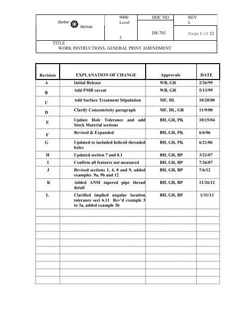
9000LevelDOC NO.REVLDS-703 Page 1 of 223TITLEWORK INSTRUCTIONS, GENERAL PRINT AMENDMENTRevision EXPLANATION OF CHANGE Approvals DATEA Initial Release WB, GR 2/26/99BCDEFGAdd PMR caveat WB, GR 5/13/99Add Surface Treatment Stipulation MF, DL 10/20/00Clarify Concentricity paragraph MF, DL, GR 11/9/00Update Hole Tolerance and addStock Material sectionsBH, GR, PK 10/15/04Revised & Expanded BH, GR, PK 6/6/06Updated to included helicoil threadedholesBH, GR, PK 6/21/06H Updated section 7 and 8.1 BH, GR, BP 3/21/07I Confirm all features not measured BH, GR, BP 7/26/07JKLRevised sections 1, 4, 8 and 9, addedexamples 9a, 9b and 12Added ANSI tapered pipe threaddetailClarified implied angular locationtolerance sect 6.11 Rev’d example 3to 3a, added example 3bBH, GR, BP 7/6/12BH, GR, BP 11/26/12BH, GR, BP 1/31/13
9000LevelDOC NO.REVLDS-703 Page 2 of 223TITLEWORK INSTRUCTIONS, GENERAL PRINT AMENDMENTRevision EXPLANATION OF CHANGE Approvals DATE
9000LevelDOC NO.REVLDS-703 Page 3 of 223TITLEWORK INSTRUCTIONS, GENERAL PRINT AMENDMENT1. Purpose2. ScopeTo define general design considerations, common machining practices, and minimuminspection requirements for parts and assemblies designed and manufactured by <strong>Barber</strong>-<strong>Nichols</strong>, <strong>Inc</strong>. and subcontractors.This work instruction applies to <strong>Barber</strong>-<strong>Nichols</strong> designed parts and assemblies whosespecifications include DS-703 as an amendment. Additionally, BNI part and assemblydrawings approved prior to 1999 are assumed to include DS-703 as an amendment unlessotherwise declared.3. ReferencesFORM, PRELIMINARY MATERIAL REVIEW, BNQF-110WORK INSTRUCTIONS, ROUTE CARDS, BNWI-90014. <strong>General</strong> Application4.1 Finished parts must meet all drawing requirements and specifications unlessotherwise exempted.4.2 Route card instructions shall take precedence over drawing specifications and thisdocument.4.3 BNI drawings may contain additional tolerancing and inspection requirements notincluded here.4.4 Application of DS-703 is limited to BNI designed parts and assemblies drawn onBNI title block or letterhead. DS-703 may be applied to parts designed and/or drawn byothers with prior agreement and as stated on the route card.4.5 Design and Engineering are responsible for the completeness and correctness of allreleased BNI drawings and models. Manufacturing is responsible for producing partsaccording to the drawing and Route Card provided. Inspection is responsible for verifyingthe completeness and correctness of the part. All part features regardless of inspectionrequirement must be accounted for.5. Specific ApplicationAll drawing specifications, dimensions and geometric tolerances are to be interpreted perANSI/ASME Y14.5M-1994 unless otherwise noted in the titleblock. Default tolerances ofsize and angularity are specified in the drawing title block. Default surface finish is specifiedin the drawing title block. Default corner chamfer and fillet radius are specified in thedrawing title block. Absent specification, parts less than 10.0 inches in diameter will have a
9000LevelDOC NO.REVLDS-703 Page 4 of 223TITLEWORK INSTRUCTIONS, GENERAL PRINT AMENDMENTmaximum corner chamfer of .02 inch and a maximum fillet radius of .04 inch. Parts 10.0inches in diameter and greater will have .02/.06 inch corner chamfers and .02/.08 fillet radii.All may be considered “Handwork”. Additional common practices for design, machining,and inspection are given below.6. <strong>General</strong> Dimensions6.1 Any suspect dimension or part condition may be verified at the discretion of QualityAssurance after visual inspection or if it has been previously identified by a PMR. (FormBNQF-110)6.2 Size tolerances for decimal dimensions of two places (or less) to the right of thedecimal point will not be verified or recorded by QA. Fractional dimensions will beconsidered “two-place” dimensions and only require inspection where noted.6.3 Size tolerances for decimal dimensions of three places, whether given specifically orby titleblock default, will be verified and documented by QA except for drilled holes as notedbelow.6.4 Size tolerances of four-place (or greater) decimal dimensions will be givenspecifically and will be verified and documented by QA except for reamed holes as notedbelow.6.5 Angular tolerances given by titleblock default will be visually inspected. Angulartolerances given specifically will be verified and documented by QA unless larger than titleblock default.6.6 Locational tolerances (true position) equal to or greater than .010 inch need not beverified or documented by QA.6.7 Orientation tolerances (perpendicularity, parallelism, angularity) equal to or greaterthan .010 inch need not be verified or documented by QA unless the tolerance is less than.001 inch per running inch of the controlled feature.EXAMPLE 1 Two faces of a 20 inch diameter cylinder are required to be parallel within.010 inch or .0005 inch per running inch of feature. Verification and documentation by QAare required.EXAMPLE 2 A 10 inch diameter cylinder 2.0 inch long is required to be perpendicular to ashoulder within .010 inch or .005 inch per running inch. Only functional inspection isrequired.6.8 Run-out tolerances (circular and total) equal to or greater than .010 inch require onlyfunctional inspection unless the tolerance is less than .001 inch per running inch of thecontrolled feature (see examples above).
9000LevelDOC NO.REVLDS-703 Page 5 of 223TITLEWORK INSTRUCTIONS, GENERAL PRINT AMENDMENT6.9 Form tolerances (flatness, straightness, circularity, cylindricity) require verificationand documentation by QA.6.10 Profile tolerances (of line or surface) only contained in a single plane, which could beinspected using a shadowgraph will be inspected. Profiles that will be inspected in thismanner (or by an equivalent method) include:Axial turbine bladesAxial stator and compressor bladesAxial fan bladesConical nozzlesConical diffusersNon-planar profiles will only be inspected by request and may require the use of an outsideinspection service.In general profile tolerances equal to or greater than .010 do not require verification ordocumentation by QA.6.11 Angular location (true position). Absent a datum controlling angular or rotationallocation of radial features a vertical or horizontal center mark on the drawing will be taken asdatum. Features located on a common vertical or horizontal center mark, or dimensionedfrom a common center mark will be located relative to one another within the sum of theirlocational tolerance.Angular location of features relative to drawing centermarks not controlled by true positionshall be within the titleblock angle tolerance. Features controlled only by their location on acentermark shall have an angular location within the title block angular tolerance.EXAMPLE 3a A radial hole passes through one wall of a cylinder at top dead center (nolocational tolerance implied) a regular hole pattern is shown in the end of the cylinder withone hole at top dead center. (The two features share a common vertical center mark line)The radial hole through the cylinder wall will be considered the clocking control for the holepattern. Any additional features located angularly from the same vertical line would also usethe radial hole as a clocking control. The implication is that all of the hole patterns controlledby true position will include the TDC hole as an angular datum. The notch shown in detailsection B – B has no locational tolerance given other than the location on the horizontalcenterline. The angular location of the notch relative to the bolt patterns and the TDCimplied datum shall be within the titleblock angular tolerance of ± 2°.EXAMPLE 3b Size tolerances for the patterned T-slot features are controlled by the profiletolerance to datums –A- and –B-. Angular location between pattern features is controlled bythe “3 EQUALLY SPACED” note which is equal to declaring a 120° BASIC angle betweenpattern features also controlled by the Profile tolerance. The drawing implies an angularrelationship between the pattern and the Ø.079 reamed hole that is controlled by the titleblock
9000LevelDOC NO.REVLDS-703 Page 6 of 223TITLEWORK INSTRUCTIONS, GENERAL PRINT AMENDMENTangular tolerance of ± 2°.7. Features on a Common AxisUncontrolled diameters on a common axis or centerline as shown on the drawing shall fallwithin the locational tolerances described below. All typical inspection requirements apply.Uncontrolled features will be inspected at Inspection’s discretion.7.1 True position from the largest datum diameter to any diameter on a common axisshall be within a cylindrical tolerance zone equal to half the sum of the total size toleranceand regardless of feature size.EXAMPLE 4 An uncontrolled shaft diameter has a size tolerance of ±.015 inch. Thelargest datum diameter has a size tolerance of ±.001 inch. The sum of the total size toleranceis .032 inch. The true position of the uncontrolled diameter must be within a cylindricaltolerance zone of .016 inch relative to the datum diameter and regardless of feature size. Ifother uncontrolled diameters exist on this shaft the tolerance zone must be calculated for eachfeature. For instance a different diameter on the common axis has a size tolerance of ±.005inch. The sum of the total size tolerance is .012 inch. This diameter must be located within a.006 inch cylindrical tolerance zone relative to the datum diameter and regardless of featuresize.7.2 True position of an uncontrolled diameter on an axis solely defined by machinedcenter datums shall be within a cylindrical tolerance zone equal to half the total size toleranceof the uncontrolled diameter and regardless of feature size.EXAMPLE 5 An uncontrolled shaft diameter has a size tolerance of ±.015 inch. The onlycylindrical datums are machined centers. The true position of the diameter must be within acylindrical tolerance zone of .015 inch relative to the axis defined by the centers andregardless of feature size.7.3 True position from the largest controlled diameter to any diameter on a common axisshall be within a cylindrical tolerance zone equal to half the sum of the total size toleranceand regardless of feature size.EXAMPLE 6 A 1.50 inch diameter cylinder (±.015 inch size tolerance by titleblockdefault) is controlled perpendicular to a face. A 2.00 diameter (±.015 in. by default) is on acommon axis but otherwise uncontrolled. The 1.50 inch diameter becomes the datumdiameter since it is controlled. True position of the 2.00 inch diameter must be within acylindrical tolerance zone of .030 inch relative to the 1.50 inch diameter and regardless offeature size.7.4 In the case where two or more diameters share a common axis, and no controls arespecified the largest or longest diameter will be considered datum. True position of any otherdiameter must be within a cylindrical tolerance zone equal to half the sum of the total sizetolerances and regardless of feature size. (See Example 4)
9000LevelDOC NO.REVLDS-703 Page 7 of 223TITLEWORK INSTRUCTIONS, GENERAL PRINT AMENDMENT8. <strong>General</strong> Holes, Drilled Holes, Reamed Holes, Threaded Holes8.1 Holes (including drilled, countersunk and counterbored holes) intended to beproduced with standard tools and absent any specified tolerance or surface finish requirementon the drawing will meet the following:Holes with multiple features such as counterbores, countersinks, chamfers, drill points, pilotholes, etc. shall be considered one feature for all locational tolerances.Unless otherwise specified drilled holes will have a 250 surface finish or better.Unless otherwise specified, the size tolerances of all holes dimensioned to 3 places are:.000 - .124 inch + .003/-.002 inch.125 - .311 inch + .010/-.004 inch.312 - .749 inch + .015/-.005 inch.750 – 1.250 inch + .020/-.010 inchTitleblock tolerances and inspection requirements apply to all other hole dimensions.Holes which require different size tolerance control, or which cannot be produced withstandard tooling must be toleranced specifically. For example Ø.495/.505 thru, even thoughthe ±.005 tolerance is standard for a three-place dimension. As a hole this must be tolerancedspecifically. Holes larger than Ø1.250 obey the titleblock tolerances.Where practical drilled holes should include a machined lead-in chamfer of .010/.020 inchwith a 90º/120º included angle. Both sides of thru holes should be chamfered. This chamfershould be considered “handwork” and need not be verified or documented by QA.Drilled hole depth refers to the depth of the full diameter of the hole. If a hole is designatedas “DRILL POINT OK” the exact drill point geometry is at the machinist’s discretion unlessspecified on the drawing. If the material under the drill point is less than 0.10 inch the workpiece will be supported to prevent dimpling.Counterbores and spot faces are flat to within .005 from I.D. to O.D. and have .012 MAXcorner fillets. Machinists must verify that the tool meets the requirement. QA need notverify or document this except at the machinist’s request.Bolt clearance holes will have locational tolerance given at maximum material condition.Bolt hole patterns located to a true position equal to or greater than .010 inch need not beverified or documented by QA. True position will be given at maximum material condition.8.2 Reamed holes intended to be produced with standard tools and absent any specifiedtolerance or surface finish requirement on the drawing will meet the following:
9000LevelDOC NO.REVLDS-703 Page 8 of 223TITLEWORK INSTRUCTIONS, GENERAL PRINT AMENDMENTReamed holes will be given as four-place decimals and will be noted as reamed holes. Forinstance as .2500 diameter ream thru or .1875 diameter ream to .250 deep.Reamed holes with multiple features such as counterbores, spot faces, chamfers and pilotholes shall be considered one feature for all locational tolerance.Unless otherwise specified reamed holes will have a 32 surface finish or better.Unless otherwise specified the size tolerances of reamed holes are:.0313 - .5000 inch + .0002/-.0000 inch.5313 - .6250 inch + .0003/-.0000 inch.6563 - 1.5000 inch + .0005/-.0001 inchTitleblock tolerances and inspection requirements apply to all other hole dimensions.Reamed hole depth refers to the depth of the full diameter of the hole. If a hole is designatedas “DRILL POINT OK” the exact drill point geometry is at the machinist’s discretion unlessspecified on the drawing. If the material under the drill point is less than 0.10 inch thick thework piece will be fully supported.Reamed holes located to a true position equal to or greater than .010 inch need not be verifiedor documented by QA. Match drilled reamed holes only require functional inspection.Reamed holes shall include a lead-in chamfer as described for drilled holes.8.3 Straight threaded holes intended to be produced with standard tools and absent anyspecifications to the contrary will meet the following:All threaded holes must carry a complete description including thread size, pitch, series,minimum full thread depth and minor diameter depth.Helicoil threaded holes must carry a complete description including nominal thread size,pitch, insert length and minor diameter depth, all preceded by the wording “Tap for Helicoil”and followed by the helicoil type.EXAMPLE 7a .250–28UNF-2B THD EXAMPLE 7b TAP for.250–28UNF Helicoil.38 min full THD depth 2.0 dia long, Type 3591-4CNMinor diameter thruMinor diameter thruEXAMPLE 8a .250–28UNF-3B THD EXAMPLE 8b TAP for.250–28UNF Helicoil.43 min full THD depth 2.0 dia long, Type 1191-4CNMinor diameter as requiredMinor diameter as requiredDRILL POINT OKFLAT BOTTOM DRILL
9000LevelDOC NO.REVLDS-703 Page 9 of 223TITLEWORK INSTRUCTIONS, GENERAL PRINT AMENDMENTIf the minor diameter depth is left to the machinist’s discretion the minor diameter depth maybe 7 thread pitches below the minimum full thread depth, or until the material thicknessbelow the drill point is 0.10 inch.Blind tapped holes that cannot include a minor diameter depth of 7 thread pitches will bespecified. Specifying “BOTTOMING TAP REQ’D” implies a minor diameter depth 3 threadpitches below the minimum full thread depth. Flat bottom drills may also be specified. Anyother relationship between the minor diameter depth and the minimum full thread depth mustbe specified be giving the minor diameter depth.EXAMPLE 9a .250–28UNF-3B THD EXAMPLE 9b TAP for.250–28UNF Helicoil.43 min full THD depth 2.0 dia long, Type 1191-4CNBOTTOMING TAP REQ’DMinor dia to depth shownMinor diameter as requiredFLAT BOTTOM DRILLDRILL POINT OKIf the material thickness under the drill point is less than 0.10 inch thick the work piece willbe fully supported when drilled to prevent dimpling.Where practical, fine threads will be used for all thread sizes. When coarse threads arespecified oversized tap drills to 80% of thread height may be used in materials of hardnessequal to or greater than RC30.EXAMPLE 10 A 316L S.S. part (RC32) requires a .375 – 16UNC -2B thread. The nominalminor diameter is 0.316 inch. Nominal thread height is .0295 inch, 80% of nominal height is.024 inch so the minor diameter could be increased to .328 inch.8.4 Straight threaded hole inspection requirementsThreaded holes with multiple features shall be considered one feature for all locationaltolerance.Threaded holes located to a true position equal to or greater than .010 inch only requirefunctional inspection for location.Class 2 threads only require functional inspection for size, pitch and thread depth. Formultiple identical features functional inspection of one tapped hole and visual confirmation ofall others is sufficient.Class 3 threads require 100% inspection for size, pitch and thread depth. For multipleidentical features on a common bolt pattern (either linear or circular) sampling of 25% of theholes per pattern (minimum of one) and visual confirmation of all others is sufficient.8.5 MS-33649 ports intended to be produced with standard tools and absent anyspecifications to the contrary will meet the following:
9000LevelDOC NO.REVLDS-703 Page 10 of 223TITLEWORK INSTRUCTIONS, GENERAL PRINT AMENDMENTAll MS-33649 ports must carry a description that includes the following:Port size, thread size, pitch, series and class, spot face depth, full thread depth, and minordiameter depth. All other port features including spot-face, counterbore, and o-ring chamfersare the responsibility of the machinist unless otherwise specified. Designating a drawingfeature as an MS-33649 port is sufficient. A detailed pictorial representation is not required.EXAMPLE 11 A part requires an MS-33649-05 port. It may be shown as a simple tappedhole. The drawing callout requires;Port per MS-33649-05.500 – 20UNJF-3B THD.45 Min full thread depthMinor diameter to depth shownSpot face to clean upImplied in this description areA .750 diameter spot face, 125 surface finish flat within .005 I.D. to O.D.A .640/.625 diameter, 120º included angle lead-in chamfer with 32 surface finishA .522/.517 diameter counterbore .090/.075 deep with 32 surface finish andA 50º/40º thread lead-in chamfer at the bottom of the counterboreAll of which are produced by the standard porting tool.Minor diameter depths should extend 7 thread pitches below the required full thread depth. Ifthis is not possible the drawing will note the minor diameter requirements. “BOTTOMINGTAP” designations apply as given above.Ports will only be functionally inspected.counterbore finishes are required.Visual inspection of spot-face and o-ringPort location tolerances equal to or greater than .010 inch will be functionally inspected.8.6 MS-16142/SAE J1926/1 ports intended to be produced with standard tools and absentany specifications to the contrary will meet the following:All MS-16142/SAE J1926/1 ports must carry a description that includes the following:Port size, thread size, pitch, series and class, spot face depth, full thread depth, and minordiameter depth. All other port features including spot-face, counterbore, and o-ring chamfersare the responsibility of the machinist unless otherwise specified. Designating a drawingfeature as an MS-16142/SAE J1926/1 or an SAE J1926/1 port is sufficient. A detailedpictorial representation is not required.EXAMPLE 12 A part requires an SAE J1926/1 port. It may be shown as a simple tappedhole. The drawing callout requires;Port per MS-16142/SAE J1926/1 -05OrPort per SAE J1926/1 -05.500 – 20UNF-2B THD
9000LevelDOC NO.REVLDS-703 Page 11 of 223TITLEWORK INSTRUCTIONS, GENERAL PRINT AMENDMENT.55 Min full thread depthMinor diameter to depth shownSpot face to clean upImplied in this description areA .906 diameter spot face, 125 surface finish flat within .005 I.D. to O.D.A .555/.551 diameter, 26º/22° included angle countersink .110/.094 deepwith a 32 surface finish.A 50º/40º thread lead-in chamfer at the bottom of the countersinkAll of which are produced by the standard porting tool.Minor diameter depths should extend 7 thread pitches below the required full thread depth. Ifthis is not possible the drawing will note the minor diameter requirements. “BOTTOMINGTAP” designations apply as given above.Ports will only be functionally inspected.countersink finishes are required.Visual inspection of spot-face and o-ringPort location tolerances equal to or greater than .010 inch will be functionally inspected.8.7 Tapered pipe (NPT) tapped ports intended to be produced with standard tools perANSI B2.1 and absent any specifications to the contrary will meet the following:All NPT holes must carry a complete description including pipe size, thread pitch and minordiameter depth. Full thread depth is assumed to be the L1 depth per ANSI B2.1 with runoutthreads to the L3 depth.If the minor diameter depth is left to the machinist’s discretion the minor diameter depth maybe 7 thread pitches below the nominal L1 thread depth, or until the material thickness belowthe drill point is 0.10 inch. There are no “BOTTOMING TAPS” for NPT threaded holes.For NPT threaded holes produced by thread milling full thread depth will be the nominal L1depth plus 2 ± 0.5 full threads to compensate for the L3 vanishing threads produced bytapping.8.8 Tapered pipe (NPT) threaded hole inspection requirements:NPT threaded holes with multiple features shall be considered one feature for all locationaltolerance.NPT threaded holes located to a true position equal to or greater than .010 inch only requirefunctional inspection for location.All NPT threads only require functional inspection for size, pitch and thread depth
9000LevelDOC NO.REVLDS-703 Page 12 of 223TITLEWORK INSTRUCTIONS, GENERAL PRINT AMENDMENT9. Radii and ChamfersAll fillet radii and corner chamfers of two decimal places to the right of the decimal point orless will be visually inspected.All fillet radii and corner chamfers noted as “hand” operations i.e. hand break, hand work,hand blend, etc., will be visually inspected. Hand operation dimensions are intended asguide. No tolerances apply unless specified.All radii and chamfers of three decimal places or more will be verified and documented byQA.10. Surface TreatmentSurface finishes of 16 or less require comparative inspection. Rougher surface finishesrequire visual inspection.Unless otherwise stated all dimensions are considered to be prior to surface treatments suchas irridite, anodize and inlox. Surface treatments that require specific machining afterapplication will be noted on the drawing. Treated surfaces that require post-treatmentinspection will be noted on the drawing, for instance anodized surfaces will frequentlyrequire pre- and post-anodize dimensional inspection.11. Stock SurfacesSurfaces defined as “stock” or “stk” do not require any additional processing to achieve theindicated dimension. Default size tolerances do not apply to stock dimensions. It isincumbent upon the designer to know if the applicable size tolerance for the type of stock (i.e.bar, plate, tube, pipe, etc.) will produce the part required.Minimum material may be removed for full clean up to improve aesthetic appearance of thepart. This material removal must not exceed .030 inches per side (.060 inch on a diameter)without engineering approval. This clean up does not apply to pipe, tube, structural tubing, orstructural shape such as angle, channel, I-beam, etc. Cosmetic clean up of pipe, tube andstructural shapes must not remove significant amounts of material or alter the shape of thepart. Abrasive cloth, abrasive grinding, bead blasting and sand blasting may be used.12. Quality DocumentsCompleted routing package
9000LevelDOC NO.REVLDS-703 Page 13 of 223TITLEWORK INSTRUCTIONS, GENERAL PRINT AMENDMENTDS-703 EXAMPLE 1 EFFECTIVE RATE CONTROL OF PARALLELISM
9000LevelDOC NO.REVLDS-703 Page 14 of 223TITLEWORK INSTRUCTIONS, GENERAL PRINT AMENDMENTDS-703 EXAMPLE 2 EFFECTIVE RATE CONTROL OF PERPENDICULARITY
9000LevelDOC NO.REVLDS-703 Page 15 of 223TITLEWORK INSTRUCTIONS, GENERAL PRINT AMENDMENTDS-703 EXAMPLE 3A IMPLIED ROTATIONAL LOCATION
9000LevelDOC NO.REVLDS-703 Page 16 of 223TITLEWORK INSTRUCTIONS, GENERAL PRINT AMENDMENTDS-703 EXAMPLE 3B IMPLIED ROTATIONAL LOCATION
9000LevelDOC NO.REVLDS-703 Page 17 of 223TITLEWORK INSTRUCTIONS, GENERAL PRINT AMENDMENTDS-703 EXAMPLE 4 IMPLIED LOCATIONAL TOLERANCE TO DATUM DIAMETERS
9000LevelDOC NO.REVLDS-703 Page 18 of 223TITLEWORK INSTRUCTIONS, GENERAL PRINT AMENDMENTDS-703 EXAMPLE 5 IMPLIED LOCATIONAL TOLERANCE TO DATUM CENTERS
9000LevelDOC NO.REVLDS-703 Page 19 of 223TITLEWORK INSTRUCTIONS, GENERAL PRINT AMENDMENTDS-703 EXAMPLE 6 IMPLIED LOCATIONAL TOLERANCE OF CYLINDERS ON ACOMMON AXIS
9000LevelDOC NO.REVLDS-703 Page 20 of 223TITLEWORK INSTRUCTIONS, GENERAL PRINT AMENDMENTDS-703 EXAMPLE 11 MS33649 PORT IMPLIED DETAIL
9000LevelDOC NO.REVLDS-703 Page 21 of 223TITLEWORK INSTRUCTIONS, GENERAL PRINT AMENDMENTDS-703 EXAMPLE 12 MS16142/SAE J1926/1 PORT IMPLIED DETAIL
9000LevelDOC NO.REVLDS-703 Page 22 of 223TITLEWORK INSTRUCTIONS, GENERAL PRINT AMENDMENT