CLOSED LOOP STEPPING SYSTEMSModel No. PB Type MDC Power Input TypeGeneral SpecificationsAmplifier ModelPB3D003M200, PB3D003M201Interface Generic Input (SW1=ON) Pulse Train Input (SW1 = OFF)Control ModePWM Control SIN drive methodPowerSupply Single Power DC24V/48V ±10% (□ 28mm Motor is only available as 24V.) Note 1EnvironmentAmbienttemp.OperatingOperating/Storage Humidity0 to 55°CStorage −20 to 70°C90% RH (non-condensing)VibrationResistance0.5G (tested with frequency range 10 to 55 Hz, X, Y, Z each direction 2H)Mass/Dimensions Approx. 0.36Kg/W32×H160×D95Rotation Speed 0 to 4500min -1Resolution (P/R) 500, 1000, 2000, 4000, 5000, 10000RegenerationProcessInternalFunctionsInput/ Output SignalsProtective FunctionsDisplayFunctionsPower Voltage Error, Regeneration Voltage Error, Over-speed, Encoder Disconnection, CPU Error, Overload Stop, Excessive PositionDeviation, Zero-return Error, Nonvolatile Memory Error, Initialization Error (Power Line Disconnection)7SEG LED DisplayNormal Drive (incremental move , absolute move), Zero-return, Module Operation,Push Operation, Teaching FunctionsPoint Functions: 128PointProgram Functions: 1PRG×1024Line 32PRG×32Line 128PRG×8LineNormal Drive, Zero-returnRotary Switch Node Adress Setting (0 to F) Normalize velocity <strong>loop</strong> gain settingDIP-Switches SSW1: Interface Selection (On: RS-485, OFF: Pulse) SW2: Terminating Resistor Setting (On: with terminating resistance)Input SignalsOutput Signals(Normal Mode) STOP, EXE, POINT, HOME, JOG, SELECT, Pause, Interlock, GenericInput, MODE SELECT, Hard Limit, ALM CLR(Teaching Mode) STOP, JOG, Point, PWRPulse input: Photo coupler: DC3V to 5V (Input resistance=270Ω)Input signal: DC5V to 24VPulse, STOP, ALMCLR, Gain Setting,Deviation Clear, HOME(Normal Mode) Ack, PEND, END, Busy, Zone, Mode MON, STOP MON, In-Position, ALM, STOP MON, In-Position, Homing complete,Homing complete, Generic Output, Encoder Output, SON MON, ALM, HEND, Encoder Output, SON MON, STOP MONInput Monitor (Teaching Mode) PEND, HEND, In-Position, Mode MON, SON MONOutput signal: Open collector DC30V / 30mA max*Encoder C-phase signal outputs within 200 min -1Communication RS-485 Standard Start-Stop Synchronization, Half DuplexSpecifications Trans.Speed9600, 38400, 115200, 128000bps 9600bpsNote 1 : Operation of the holding brake is not available when the single input voltage amplifier is used at 48V input voltage. If operation of the holding brake is required at 48V input voltage, please useamplifier model PB3D003M201 (separate voltage type) with control voltage (CN4-3pin/common GND with main circuit) set at 24V.Amplifier Dimensional Drawing63220ø530MAX. 954(Unit:mm)<strong>Industrial</strong> <strong>Technologies</strong>510Model No. PBRSWCN6Direction ofInstallationUpCN5160150CN1140CN2CN3CN42955Индастриал Технолоджис www.ind-techno.com.ua +38 044 596 04 29
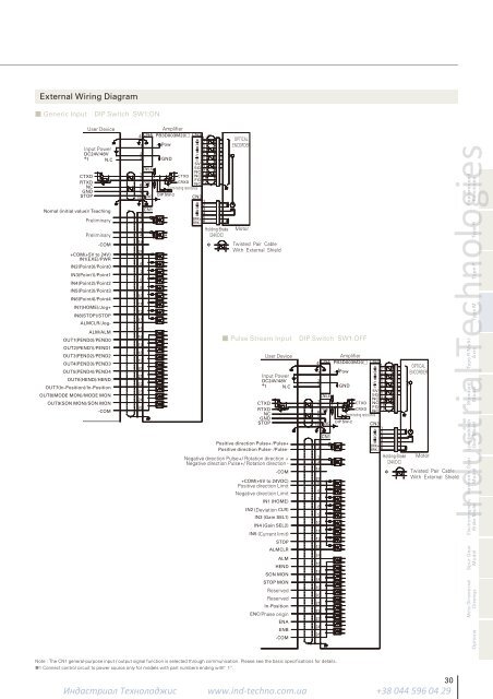
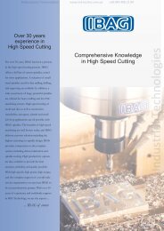
External Wiring Diagram■ Generic Input DIP Switch SW1:ONUser DeviceInput PowerDC24V/48V* 1 N.CCTXDRTXDNCGNDSTOPNomal (initial value)/ TeachingPreliminaryPreliminaryType R Multi-Axis-COM+COM(+5V to 24V)IN1(EXE)/PWRIN2(Point0)/Point0IN3(Point1)/Point1IN4(Point2)/Point2IN5(Point3)/Point3IN6(Point4)/Point4IN7(HOME)/Jog+IN8(STOP)/STOPALMCLR/Jog-ALM/ALMOUT1(PEND0)/PEND0OUT2(PEND1)/PEND1OUT3(PEND2)/PEND2OUT4(PEND3)/PEND3OUT5(PEND4)/PEND4OUT6(HEND)/HENDOUT7(In-Position)/In-PositionOUT8(MODE MON)/MODE MONOUT9(SON MON)/SON MON-COM123CN11234142556789101112131516171819202122232426CN21AOPTICAL2PowAB3ENCORDERB4C5GNDC65V75G8NC9NC10CTXDFG11CRXD 12NCTerminating resistanceDIP SW-2CN31A2A3 BB4BRK+5BRK-6Holding Brake Motor24VDC* Twisted Pair CableWith External Shield4 CN4 AmplifierPB3D003M20□CN5,612Vcc65710GND■ Pulse Stream Input DIP Switch SW1:OFFUser DeviceInput PowerDC24V/48V* 1 N.CCTXDRTXDNCGNDSTOPPositive direction Pulse+ /Pulse+Positive direction Pulse- /Pulse-Negative direction Pulse+/ Rotation direction +Negative direction Pulse+/ Rotation direction --COM+COM(+5V to 24VDC)Positive direction LimitNegative direction LimitIN1 (HOME)IN2 (Deviation CLR)IN3 (Gain SEL1)IN4 (Gain SEL2)IN5 (Current limit)STOPALMCLRALMHENDSON MONSTOP MONReservedReservedIn-PositionENC/Phase originENAENB-COM123CN11234142556789101112131516171819202122232426CN21AOPTICAL2PowAB3ENCORDERB4C5GNDC65V75G8NC9NC10CTXDFG11CRXD 12NCTerminating resistanceDIP SW-2CN31A2A3 BB4BRK+5BRK-6Holding Brake Motor24VDC* Twisted Pair CableWith External Shield4 CN4 AmplifierPB3D003M20□CN5,612Vcc65710GND<strong>Industrial</strong> <strong>Technologies</strong>Features andFunctionsType RType PType MStandardModelLow-backlashGear ModelHarmonic GearModelElectromagneticBrake ModelSpur GearModelMotor DimensionalDrawingsOptionsNote : The CN1 general-purpose input / output signal function is selected through communication. Please see the basic specifications for details.*1 Connect control circuit to power source only for models with part numbers ending with “ 1”.Индастриал Технолоджис www.ind-techno.com.ua +38 044 596 04 2930