CSPAR - PEO STRI - U.S. Army
CSPAR - PEO STRI - U.S. Army
CSPAR - PEO STRI - U.S. Army

Create successful ePaper yourself
Turn your PDF publications into a flip-book with our unique Google optimized e-Paper software.
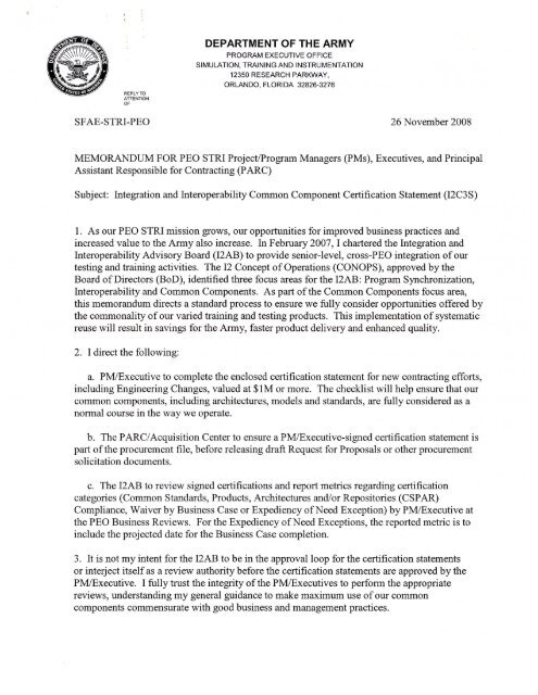
<strong>PEO</strong> <strong>STRI</strong><br />
Common Standards, Products, Architectures and/or Repositories<br />
(<strong>CSPAR</strong>) Baseline Document<br />
Version 1.0<br />
16 October 2006<br />
U.S. <strong>Army</strong> Program Executive Office (<strong>PEO</strong>)<br />
Simulation, Training and Instrumentation (<strong>STRI</strong>)<br />
12350 Research Parkway<br />
Orlando, FL 32826-3276
Table of Contents<br />
Introduction..................................................................................................................................... 1<br />
1.0 Architectures / Frameworks..................................................................................................... 2<br />
2.0 Common Products / Components .......................................................................................... 13<br />
3.0 Standards ............................................................................................................................... 21<br />
4.0 Common Interfaces/DIFs....................................................................................................... 19<br />
5.0 Data Models........................................................................................................................... 25<br />
6.0 Processes/Guidelines.............................................................................................................. 26<br />
7.0 Repositories............................................................................................................................ 28<br />
8.0 Near Future Components ....................................................................................................... 28<br />
Page ii
Introduction<br />
The <strong>PEO</strong> <strong>STRI</strong> Common Standards, Products, Architectures, and/or Repositories (<strong>CSPAR</strong>)<br />
baseline document provides overview information associated with items identified in the <strong>PEO</strong><br />
<strong>STRI</strong> <strong>CSPAR</strong> Policy memo dated 16 October 2006.<br />
This document is divided into eight sections, one for each type of artifact and a final section on<br />
potential future components or standards. Each artifact section provides details on the<br />
identification, description, and current version number/description and a point of contact. The<br />
potential future components section is a list of items that are in development that the EASC may<br />
incorporated into future versions of the baseline document.<br />
Page 1
1.0 Architectures / Frameworks<br />
1.1 Architecture/Framework ID: Common Training Instrumentation Architecture (CTIA)<br />
1.1.1 Architecture/Framework Description: CTIA is the software framework by which the<br />
PM TRADE Live Training Transformation (LT2) strategy will develop product line components<br />
that are re-usable and composed to instantiate multiple Instrumentation Training Systems that<br />
shall be deployed to Combat Training Centers, Homestations, and instrumented ranges. The<br />
CTIA program provides the framework (protocols, standards, interfaces, etc.) and interfaces with<br />
other live, virtual and constructive environments. CTIA is also a Future Combat Systems (FCS)<br />
complementary program that is a major contributor to the FCS Training Common Components.<br />
CTIA represents <strong>PEO</strong> <strong>STRI</strong>s common architecture for the Live Training Domain and its strategy<br />
to interoperate with other <strong>PEO</strong> <strong>STRI</strong> Virtual and Constructive Domains.<br />
Additional information on CTIA can be found at the following web sites:<br />
LT2 SharePoint: https://ace.peostri.army.mil/sites/pmtrade/LT2/default.aspx<br />
LT2 Portal: https://www.lt2portal.org/<br />
Components are a defined portion of the architecture that can be “plugged in and out.” A<br />
component has a set of requirements it must meet, a well defined and managed interface<br />
specification, and a well-defined capability. Within CTIA these components support<br />
requirements variability, reuse, extensibility, adaptability and autonomous development. The<br />
CTIA compliant plug and play components may be common to multiple products or unique to a<br />
specific product. The plug and play components have been divided into two primary types,<br />
instrumentation and processor. These two types of plug and play components are described<br />
below.<br />
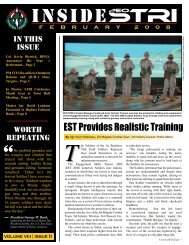
Figure 1 below provides a layered view of the component based CTIA client-server architecture.<br />
The infrastructure components of the architecture include:<br />
Page 2
CTIA Services<br />
•Event Services<br />
•Tracking Services<br />
•Exercise Services<br />
•Streaming Data Services<br />
•Tactical Systems Services<br />
•TENA Services<br />
Wired Communications<br />
Instrumentation<br />
•Tracker<br />
•Audio Stream Sensor<br />
•Video Stream Sensor<br />
•TESS Interface<br />
•Detector<br />
•TESS Device<br />
•Audio Stimulator<br />
•Video Stimulator<br />
•Binary Stimulator<br />
•Variable Stimulator<br />
•Target System Interface<br />
•Digital System Interface<br />
Figure 1 – CTIA Client-Server Architecture<br />
Processors<br />
•Interactive<br />
•Non-Interactive<br />
•ICTS<br />
Data Distribution Manager (DDM)<br />
CORBA Industry Std<br />
Operating System (OS)<br />
Windows/Linux<br />
Wireless Communications<br />
• Processors – This category of components have the capability of producing and<br />
consuming all types of CTIA data. This includes tools like After Action Review (AAR)<br />
Analysis and Exercise Monitoring as well as Computer Generated Forces (CGF).<br />
Processor components can be interactive or non-interactive. Interactive processor<br />
components have a user interface and are comprised of the common toolset required<br />
across the family of LT2 systems to plan, prepare, execute and evaluate training. Noninteractive<br />
processor components include gateways to other simulation or training<br />
systems and instrumentation system-based simulations (e.g., Area Weapon Effects).<br />
Processors components encapsulate computational functions that have the capability of<br />
producing and consuming all types of CTIA data.<br />
• Instrumentation – This category of components encapsulates the hardware and software<br />
needed to collect data from and control live entities. Instrumentation is typically<br />
associated with live participants but can be used for simulated. Instrumentation<br />
components provide the interfaces to other subsystems and systems such as Tactical<br />
Engagement Simulation Systems (TESS), target systems, and Command and Control<br />
(C2) systems. In addition, they provide encapsulation of instrumentation such as<br />
individual TESS devices, trackers, video cameras, Battlefield Effects Simulators, and<br />
control devices in a Mobile Operations on Urban Terrain (MOUT) facility.<br />
• CTIA Services – The CTIA Services provide domain specific services to support plug<br />
and play component clients. When deployed, these services are tailored to account for<br />
Page 3
things such as training exercise scale, available infrastructure, and network variability.<br />
The service interfaces use a predefined object data model to ensure component<br />
interoperability and eliminate “stove pipe” systems. These interfaces are defined using<br />
the Common Object Request Broker Architecture (CORBA) interface definition language<br />
(IDL), which defines object data structures without methods. The CTIA Object Models<br />
provide methods and higher-level abstractions (e.g. proxies for remote objects). The<br />
CTIA services maintain objects representing exercises, organizations, and participants. It<br />
provides services accessible through the Data Distribution Management (DDM) such as<br />
unique ID, entity filtering, and brokering control of instrumentation. It provides access to<br />
databases for exercise specific and exercise independent data, and encapsulates the<br />
databases.<br />
• Communication – These components provide communications between system elements<br />
either through wired or wireless networks.<br />
• DDM and Operating System – These components are necessary to complete the<br />
definition of the system. DDM provides the back-bone into which other components<br />
plug into.<br />
1.1.2 Architecture/Framework Version: CTIA Spiral 5<br />
1.1.3 POC: Will Samper (407) 384-3626<br />
1.2 Architecture/Framework ID: <strong>Army</strong> Training Information Architecture (ATIA)<br />
1.2.1. Architecture/Framework Description<br />
The ATIA-Migrated (ATIA-M) architecture is divided into components represented by<br />
Automated Information Systems (AIS) that support, by applying a “self-organizing-to-task”<br />
operations concept, six ATIA-M User Configurations. The functionality of the architecture<br />
resides in nine AISs as software objects, frequently as Enterprise Java Beans (EJBs). These<br />
AISs are used as the building blocks for six user configurations. An analogy would be to<br />
compare the AISs to collections of Lego TM pieces. Each user configuration is assembled, as<br />
needed, from the component functions contained in the AISs. Data are not allocated to AIS. All<br />
training data, including reference tables, are stored in the ATIA-M Enterprise Database (EDB).<br />
All software objects are part of the common architecture, subscribe to common development<br />
standards, and use the EDB as the common storage location. The physical instantiation of ATIA<br />
is called the ATIA-M.<br />
Two AISs, Common Core Services (CCS) and Digital Library/Data Repository (DLDR), are<br />
common to all user configurations. The former provides much of the infrastructure services,<br />
such as login, security, and user interaction, while the latter manages the collection of finished<br />
training products in the Reimer Digital Library and the “bench stock” (courseware component<br />
parts) for training developers and other required data in the Data Repository. Access to and<br />
interoperability with ATIA-M is through CCS. Access to ATIA-M products and data is through<br />
DLDR.<br />
Page 4
1.2.2 ATIA-M Interoperability Domains<br />
ATIA-M currently provides for interoperability in three separate domains. They are as follows:<br />
• Data Extraction<br />
• Data Injection<br />
• Function Point Development<br />
1.2.2.1 Data Extraction Domain<br />
The Data Extraction Domain is the simplest level of ATIA-M interoperability. Extraction of<br />
data is accomplished via web services.<br />
Access to ATIA-M objects is accomplished by using both the CCS and DLDR AISs. The CCS<br />
will provide authentication and identification and the DLDR will provide access to the ATIA-M<br />
data objects repository.<br />
Access to both AISs will be via ATIA-M web services.<br />
1.2.2.2 Data Injection Domain<br />
The Data Injection Domain is the next level of ATIA-M interoperability and represents injecting<br />
new or modified data into ATIA-M. ATIA-M uses well defined application programmers<br />
interfaces (API) that are used to inject data objects into ATIA-M. It is also possible to inject<br />
documents into the DLDR. These documents must be in one of the accepted formats for<br />
documents.<br />
The ability to inject data into ATIA-M is accomplished by using the CCS and the DLDR AISs.<br />
As with the Data Extraction Domain, the CCS will provide user authentication and identification<br />
and the DLDR will provide access to the ATIA-M data objects.<br />
Access to both AISs will be via ATIA-M web services.<br />
1.2.2.3 Function Point Development Domain<br />
The Function Point Development Domain is the most complex level of ATIA-M interoperability.<br />
This domain describes how a software development team might develop a function point that<br />
would be fully integrated (and thus, interoperable) with ATIA-M. The ATIA-M architecture is<br />
such that many development teams may write software that will exist within this domain.<br />
To interoperate with ATIA-M in the Function Point Developer Domain, the developer will have<br />
to conform to the ATIA-M development and coding standards. The ATIA-M Function Point<br />
software will have to be compiled and packed in the same manner as ATIA-M AIS software.<br />
Page 5
1.2.2.4 Architecture/Framework Version: ATIA-M Version 5.3 which was deployed to the<br />
ATIA-M Production Environment in April of 2006.<br />
1.2.2.5 POC: Harry Sotomayor (407) 384-3608<br />
1.3 Architecture/Framework ID: SE Core Virtual Simulation Architecture (VSA)<br />
1.3.1 Architecture/Framework Description: PM CATT has established the Virtual<br />
Simulation Architecture (VSA) as the architecture for the virtual simulation domain. The<br />
Synthetic Environment (SE) Core program is developing VSA as a common Product Line<br />
Architecture (PLA) supporting the development of new and the evolution of current <strong>PEO</strong> <strong>STRI</strong><br />
virtual simulation training systems. The VSA applies the PLA concepts to provide a set of<br />
reusable products, components, services interfaces, and standards that allow current and future<br />
<strong>PEO</strong> <strong>STRI</strong> programs to satisfy their service needs.<br />
The PM CATT end goal is to have a full product line of virtual training simulation systems based<br />
on the VSA architecture and products. For current systems, VSA products can satisfy the need<br />
for increased functionality, technology refresh, and reduction of operational and maintenance<br />
costs. A business case analysis and phased evolution path will determine how rapidly the current<br />
systems will adopt the VSA.<br />
The SE Core program is influencing the VSA from a product line perspective by providing a<br />
product line tool-box consisting of architectural definitions and rules along with a set of common<br />
core product line assets or building blocks.<br />
1.3.1.1 Major Technical Drivers<br />
Four motivations are identified as the main technical drivers for the VSA: interoperability,<br />
reuse, current system investment and adaptability and extensibility.<br />
1.3.1.1.1. Interoperability<br />
VSA defines and addresses interoperability between multiple products deployed within a training<br />
system and between multiple training systems. In each case, the interoperability capability must<br />
address:<br />
A common data model/protocol set to provide a common language (e.g., understand and speak<br />
the same language), a common time management to provide time synchronization throughout the<br />
simulation, a common sense of place provided via a common correlated synthetic natural<br />
environment (SNE) and a commonality of essential model behavior to ensure realistic<br />
interactions between simulation entities (fair fight).<br />
1.3.1.1.2. Reuse<br />
To eliminate the duplicate development and sustainment costs of the traditional stovepipe<br />
development, major software applications must be available for reuse across the domain. This<br />
Page 6
equires a common repository for the reusable software such that individual programs can locate,<br />
understand, and tailor reuse candidates with the minimum amount of effort. Additionally, the<br />
VSA must maximize support for incorporating software from current training systems.<br />
1.3.1.1.3. Current System Investment<br />
The <strong>Army</strong> has significant human and capital investment in existing training systems. Much of<br />
the near term usage of the VSA will be to update and evolve the current <strong>PEO</strong> <strong>STRI</strong> virtual<br />
training systems. The VSA must provide a cost effective path for these programs to migrate<br />
toward the VSA to allow those systems to reap the reuse and interoperability benefits of the<br />
VSA. Consideration must also be made to avoid interruption to the ongoing training capabilities<br />
of these systems during that migration.<br />
Additionally, there is a great deal of working functionality within the current systems that should<br />
be leveraged and made available through the VSA. The VSA will facilitate the minimization of<br />
effort associated with reusing that functionality.<br />
1.3.1.1.4. Adaptability and Extensibility<br />
The realities of the contemporary operating environment (COE) (emerging technologies and<br />
doctrine that support the Warfighter) are important to <strong>Army</strong> transformation and result in the need<br />
for virtual simulation systems to support new platforms, doctrine, and tactics, techniques and<br />
procedures (TTP). These new capabilities are added to current and future virtual simulation<br />
systems in the form of new and modified models, visuals, and behaviors. Consider also the<br />
diversity of the <strong>Army</strong>’s virtual training domain, which includes individual, crew, collective and<br />
combined arms. This, along with the advancements in virtual simulation technology, is<br />
broadening the operational capability that can be represented by these virtual training systems.<br />
Virtual simulation systems must be extendable to support these changes. The flexibility to adapt<br />
quickly, affordably, and sustainably must be designed into a virtual simulation system. The<br />
future training system requirements for these domains can be anticipated to a limited extent. For<br />
VSA to be relevant now and in the future, it must be extendable to support the evolving<br />
requirements of each of these training domains. Otherwise, the significant development<br />
investment in the virtual simulation system is lost because the system becomes irrelevant over<br />
time.<br />
1.3.2. VSA Definition<br />
The VSA is specified in the Product Line Architecture Specification (PLAS) document. The<br />
PLAS provides SE Core program stakeholders (end users, clients, customer, developers, etc.)<br />
with multiple integrated architectural views of the VSA. The primary focus of this document is<br />
product line decomposition, architectural boundaries, and overall interoperability interfaces,<br />
which are all necessary for proper component development and use. Figure 2 - PLAS Document<br />
Breakdown, illustrates the various specifications and architecture views contained in the VSA<br />
PLAS.<br />
Page 7
Requirements<br />
Based<br />
Engineering<br />
Processes<br />
Architectural<br />
Element<br />
Overviews<br />
Key<br />
System<br />
Threads<br />
1.3.2.1 VSA PLAF<br />
PLAS<br />
The The Product Product Line Line Architectural Architectural Specification Specification (PLAS) (PLAS) comprises comprises<br />
definitions, definitions, views, views, rules, rules, and and service service descriptions descriptions that that describe describe<br />
the the theory theory and and application application of of the the SE SE Core Core Architecture.<br />
Architecture.<br />
Motivations<br />
& Quality<br />
Attributes<br />
Compliance<br />
Rules<br />
DoDAF<br />
Views DoDAF<br />
Products<br />
AV<br />
Product Line<br />
Architectural<br />
Framework<br />
(PLAF)<br />
Layering<br />
Rules<br />
DoDAF<br />
Views DoDAF<br />
Views DoDAF<br />
Views DoDAF<br />
Products<br />
OV<br />
Component<br />
Contracts<br />
Composition<br />
Rules<br />
Figure 2 - PLAS Document Breakdown<br />
DoDAF<br />
Views DoDAF<br />
Views DoDAF<br />
Views DoDAF<br />
Views DoDAF<br />
Products<br />
SV<br />
DoDAF<br />
Views DoDAF<br />
Products<br />
TV<br />
Theory of<br />
Operations<br />
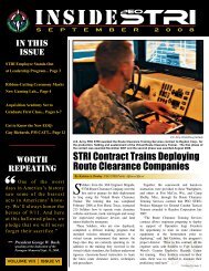
One essential view contained within the PLAS is the Product Line Architecture Framework<br />
(PLAF), which is a two-dimensional view providing a high-level quick reference for engineering<br />
and other technical staff. The boxes contained in the bottom of Figure 3 (labeled “System View”<br />
on the right) represent the functional pieces of the VSA PLA. The PLAF view shows the<br />
architectural layered organization of the VSA. That same layering is also reflected in much of<br />
the VSA PLAS document structure. The PLAF is a tool intended to assist the developers of<br />
systems, by helping them identify the architectural components, boundaries, breakdowns, and<br />
typical compositional relationships between the layers of the architectural elements.<br />
Page 8
Figure 3 – VSA PLAF<br />
The VSA PLAF system view area is divided into the following layers:<br />
1. Training Segments – Training segments list the major groupings or segments of training<br />
systems within the VSA domain.<br />
2. Operational Capability – The operational capability layer shows the high-level training<br />
operational activities performed by the domain training systems. The operational activities<br />
describe the major tasks/functions that are required for the domain training system sites to<br />
accomplish their missions.<br />
3. Product – Products are stand-alone, end-user visible functionality representing the very high<br />
level applications or application suites that are typically deployed as a unit. They represent<br />
significant architectural pieces of a training system, such as an AAR or instructor operator<br />
station (IOS). The VSA defines the specific interface protocols to facilitate the Product level<br />
interoperability.<br />
4. Subproduct – Subproducts are just smaller scale products and maintain the same<br />
characterizations as a product. The hardware analogy is that of a line replaceable unit<br />
(LRU), allowing substantial subsystem level functionality to be swapped out within a<br />
Operational<br />
View (OV)<br />
System View (SV)<br />
Page 9
training system. Subproducts will often be deployed into a training system as a collection<br />
composing a full Product; however, they may be deployed individually as necessary to meet<br />
a specific training system’s needs. For example, a simulation controller Subproduct may be<br />
deployed at an AAR workstation, allowing an operator to perform exercise control from that<br />
physical station area.<br />
5. Component – Components are the systematically reusable building blocks of Products and<br />
Subproducts. This is where the majority of software is produced within the VSA framework.<br />
Components are built on the VSA services providing further software reuse, portability, and<br />
interoperability.<br />
6. Service – The VSA services are a set of common software service interfaces that provide the<br />
framework or infrastructure on which VSA common components are built. The common<br />
services promote systematic reuse and consistency for component distribution, component<br />
and service discovery, data models, data distribution, component<br />
communications/messaging, scaling, and portability across the VSA common components.<br />
7. Platform – The platform layer represents the host hardware, operating systems, and network<br />
technology supported by the VSA. This is typically commercial off-the-shelf (COTS) or<br />
open source and is not being developed by SE Core Architecture and Integration (A&I). The<br />
VSA will, however, specify requirements on this layer such as real time execution support<br />
1.3.2.2 Architectural Element Specification<br />
The contents of the Product/Subproduct, component, and service layers are referred to<br />
collectively as VSA architectural elements. These architectural elements represent the set of<br />
reusable core assets that can be leveraged by the developers of systems. Each architectural<br />
element within the VSA is specified by a component contract. A component contract is a<br />
uniform collection of information and artifacts providing a description of an architectural<br />
element within the VSA and is intended for use by architectural element and training system<br />
developers. It provides a description of the architectural element, specifies functional<br />
requirements and interfaces, and captures other information such as known limitations, specific<br />
to each implementation instance. It supports distributed development and systematic reuse by<br />
describing the necessary interactions of the "black box" component with its environment.<br />
1.3.3 VSA Client (Customer) Support<br />
For the VSA and the SE Core A&I program to be successful, the VSA definition, products, and<br />
architectural elements must be readily and easily accessible, must be understandable, and must<br />
assist users with processes and tools to help stand up or extend a development environment.<br />
These needs are fulfilled by the SE Core repository.<br />
The SE Core repository is web-based, containing the VSA definition documentation,<br />
architectural elements and their corresponding documentation, composition tools, development<br />
processes, and build procedures.<br />
VSA client programs and product developers will access the repository though a web-based<br />
portal. Interfaces for developers to locate Products and Components of interest are currently<br />
Page 10
eing developed and include a graphical drill-down capability through an interactive PLAF view<br />
and a keyword search capability. Once located, the component contract will point to all<br />
information necessary to select, build, interface to, test, and extend the element. System<br />
developers then improve and expand the SE Core A&I baseline with feedback of to the VSA,<br />
including requests for new or expanded elements and discrepancy reports against existing<br />
architectural elements. Evolution and maintenance of the VSA and elements within the<br />
repository are managed by an architecture review board. Repository procedures will be<br />
developed to ensure existing users of the element are not adversely affected by changes and the<br />
modified element meets the specifications in the component contract.<br />
Another client program support feature is the VSA Evolution Plan (VEP). In accordance with<br />
the major motivation to preserve investments in current training systems, the VEP describes the<br />
philosophy and processes for planning and migrating current systems to the VSA. It will aid in<br />
identifying areas of opportunity for evolution including the development of the business case and<br />
estimating the engineering effort. Analysis of the candidate program architecture helps identify<br />
low hanging fruit where the program can reap improvements with minimal costs. Compliance<br />
assessment tools help evaluate the distance of a system from the VSA and the cost of the<br />
evolution. As programs move through this evolution process, data will be collected to form a<br />
historical base. Access to that history will help to refine the processes and improve the<br />
estimation speed and accuracy.<br />
As programs adopt VSA products, they also adopt the VSA framework protocols and rules,<br />
making it easier to adopt and interoperate with further Products. The end state of this evolution<br />
is a training system that conforms to, and is consistent with, the VSA Products line.<br />
1.3.4 Architecture/Framework Version: SE Core VSA Version 1.0<br />
1.3.5 POC: Brian Kemper (407) 384-3816<br />
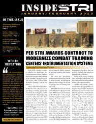
1.4 Architecture/Framework ID: Test and Training Enabling Architecture (TENA)<br />
1.4.1 Architecture/Framework Description<br />
TENA is a common architecture and requisite software suite developed by the Office of the<br />
Secretary of Defense (OSD) Central Test and Evaluation Investment Program (CTEIP) to<br />
integrate testing, training, simulation, and high performance computing technologies distributed<br />
across many facilities. The establishment of TENA fosters reuse and interoperability of range<br />
assets as well as reducing range development, operation and maintenance costs. TENA is also<br />
the Joint National Training Capability (JNTC) architecture for live training and is used primarily<br />
as a communication architecture.<br />
Page 11
Figure 4 – TENA Architecture<br />
The core of TENA is the TENA Common Infrastructure, including the TENA Middleware, the<br />
TENA Repository, and the TENA Logical Range Data Archive. There is also the TENA Object<br />
Model, which defines the common data and interfaces shared by all range applications. There<br />
are also a number of tools, utilities, and gateways to enable many range resources located at<br />
geographically dispersed ranges to be integrated together.<br />
TENA Middleware: A high performance, real-time, low-latency communication infrastructure<br />
used by range resource applications and tools during the execution of a range event. The TENA<br />
Middleware facilitates all data exchange and control commands between range systems. More<br />
importantly, the TENA Middleware provides range system developers with a unified API to<br />
support the real-time exchange of software objects, messages and data streams.<br />
TENA Repository: Contains all the information relevant to TENA that is not specific to a given<br />
test or training event. The TENA Repository is web-enabled and functions, in essence, as a large<br />
database of databases, allowing event planners to browse and select capabilities that can be<br />
easily configured and used to support an event.<br />
TENA Logical Range Data Archive: Stores and allows retrieval of all the persistent information<br />
associated with a test or training event.<br />
TENA Website: www.tena-sda.org<br />
TENA Sharepoint: https://pmitts.peostri.army.mil/default.aspx<br />
Go to ‘Shared Documents’<br />
Go to ‘TENA Information’<br />
Page 12
1.4.2 Architecture/Framework Version: The current release version of the TENA<br />
Middleware is Release v5.1.1<br />
1.4.3 POC: Carleton Stargel (407) 384-3878<br />
2.0 Common Products / Components<br />
2.1. Component ID: One Semi-Automated Forces (OneSAF) Simulation Core Product and<br />
supporting components<br />
2.1.1. Component Description: OneSAF is a composable CGF that represents a full range of<br />
operations, systems, and control processes from the individual combatant and platform level to<br />
fully automated BLUFOR battalion level and fully automated OPFOR brigade level. Unit<br />
behaviors will be modeled to the BLUFOR battalion and OPFOR brigade level for selected units,<br />
and command entities will be modeled to the BLUFOR brigade and OPFOR division level.<br />
OneSAF will have a variable level of fidelity that supports modeling and simulation (M&S)<br />
domains. It will accurately and effectively represent specific activities of command, control,<br />
communications, computers, intelligence, surveillance and reconnaissance (C4ISR), combat<br />
support (CS), and combat service support (CSS). It will also employ appropriate representations<br />
used to meet the current force (including the Stryker Brigade Combat Team) requirements and<br />
facilitate meeting future M&S efforts like Future Combat System (FCS), Modeling Architecture<br />
for Research, Technology and Experimentation (MATRIX), or Battle Lab Collaborative<br />
Simulation Environment (BLCSE).<br />
2.1.2 Component Version Description (e.g., VDD). OneSAF version 1.0<br />
2.1.3 POC: Tamara Griffith (407) 384-3636<br />
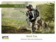
2.2 Component ID: Warfighters’ Simulation (WARSIM) Aggregate Models/Behaviors<br />
2.2.1 Component Description: WARSIM is a next-generation, large-scale constructive<br />
wargaming system, developed for U.S. <strong>Army</strong> command and control training. It is being<br />
developed to replace the current legacy simulation systems, e.g., Corps Battle Simulation (CBS)<br />
and Tactical Simulation (TACSIM). WARSIM is a significant advance in modeling and<br />
simulation technology deploying a wide range of resolution, fidelity and abstraction, depending<br />
on its specific use. WARSIM is a distributed, constructive wargaming simulation, designed to<br />
create a single, seamlessly integrated synthetic battlespace, including a common environmental<br />
and operational picture. Interfacing with C4I functions and equipment in the field to provide the<br />
interface between the synthetic battlespace and the training audience, WARSIM creates a<br />
training environment intended to be indistinguishable from the real-world by the training<br />
audience.<br />
WARSIM is a constructive simulation system used to train commanders and staffs at brigade,<br />
division, corps and echelons above corps. When conducting an exercise, it can be viewed as<br />
Page 13
three layers. At the top is the training audience. The training audience consists of the<br />
commanders and staffs of the units to be trained, organized and equipped as they would be in an<br />
operational setting. Their command posts may be field locations or they may be at a training<br />
center, but they are equipped with the tactical C4I devices that would be used to conduct actual<br />
operations.<br />
The second layer is a set of “role players.” These are people who perform the roles of the<br />
subordinate commanders and staffs of the training audience. They interact with the training<br />
audience via tactical communications and C4I tactical messages to provide the stimuli that allow<br />
a training exercise to proceed. The role players also control the third layer of WARSIM, which<br />
is the computer simulation of the battlespace. The role players provide the military skills to<br />
direct the simulated units and to represent the persons with which the training audience expects<br />
to interact. In particular, the role players provide the person-to-person voice interactions that<br />
characterize <strong>Army</strong> command and control even in this digital era. At this point, there is some<br />
ability to exchange message traffic between the simulated units and the training audience without<br />
role player intervention, but this accounts for only a small part of the interaction. The three-layer<br />
structure is shown in Figure 5.<br />
Voice and Digital<br />
Message<br />
I t ti<br />
Interactions via<br />
role player<br />
workstation<br />
Interface to<br />
other JLCCTC<br />
Simulations<br />
Training Audience<br />
Controllers/Role Players<br />
Computer Simulation<br />
Direct<br />
Digital<br />
Message<br />
Interactions<br />
between<br />
Training<br />
Audience<br />
and<br />
Simulation<br />
Figure 5 - WARSIM 3-Layer Architecture<br />
Since the training audience operates with its own equipment during an exercise, the boundary of<br />
WARSIM consists of the lower two layers and the interfaces to the training audience.<br />
The simulation component of WARSIM is a real-time model of military forces on a highly<br />
detailed representation of the terrain. It provides automated units at company level that are<br />
capable of accepting orders from role players, planning the execution of those orders and<br />
controlling the actions of subordinates (e.g., platoons). The simulation provides a level of<br />
resolution such that positions of individual vehicles can be determined. Resolution of combat<br />
Page 14
engagements occurs via simulation of the weapons effects as affected by both the terrain and the<br />
ability and condition of the simulated units. This level of detail allows the simulation to provide<br />
detailed output to role players and to the training audience such as would be provided by the<br />
Warsim Intelligence Module (WIM) sensors, i.e. Unmanned Aerial Vehicles (UAVs) and by the<br />
Moving Target Indicator (MTI) Radar of a Joint Surveillance Targeting and Attack Radar<br />
System (J-STARS) aircraft.<br />
WARSIM is a multi-sided game. Opposing forces are controlled by role players trained in<br />
OPFOR tactics and operations. Civilians, military and paramilitary forces can be assigned<br />
varying allegiances to provide the complex political and military environments necessary to train<br />
commanders to deal with today’s world.<br />
Because the performance parameters associated with many present day weapons and sensors are<br />
classified, WARSIM must be able to handle and control classified information up to Top Secret<br />
Special Compartmentalized Information (TS-SCI).<br />
The System Architecture is a composition of the WARSIM hardware and software along with<br />
COTS and Government-Off-The-Shelf (GOTS) software products. The design is based on the<br />
Defense Modeling and Simulation Office (DMSO) developed High Level Architecture (HLA).<br />
Communication between elements of the system is accomplished by use of the WARSIM<br />
Federation Object Model (FOM) and the HLA Run Time Infrastructure (RTI). Figure 6<br />
illustrates the abstract relationship between the major components. The Computer Simulation<br />
piece can be viewed as four separate partitions:<br />
• Interface to the Training Audience<br />
• Simulation<br />
• Controller Interface<br />
• Infrastructure<br />
Page 15
JLCCTC<br />
Interface<br />
Controller<br />
Interface<br />
Training<br />
Audience<br />
Controllers/<br />
Role Players<br />
Simulation<br />
Infrastructure<br />
Figure 6 - WARSIM Abstract System Architecture<br />
Training<br />
Audience<br />
Interface<br />
The three layer structure discussed earlier and shown in Figure can be seen in Figure . The<br />
lowest layer represents the hardware and software that is installed at a training center. It is<br />
divided into four partitions.<br />
• The simulation partition models the battlespace and battlespace elements that model<br />
the combat activity used to stimulate the training audience.<br />
• The training audience interface partition connects the training audience C4I equipment<br />
or surrogates with the simulation and with the controller stations.<br />
• The controller interface partition allows the simulation controllers and analysts to<br />
interact with the training audience, control simulated units, and monitor the simulation<br />
system.<br />
The infrastructure partition provides common services required by all components of the<br />
simulation system.<br />
2.2.2 Component Version: WARSIM Version 3.0<br />
2.2.3 POC: Dan Griffin (407) 384-3984<br />
2.3 Component ID: WARSIM Intelligence Module (WIM)<br />
Page 16
2.3.1 Component Description: WIM is being developed to replace the current legacy<br />
simulation system, TACSIM. WIM reuses applicable technology and functionality from<br />
prototypes in intelligence simulations, such as the Federation of Intelligence, Reconnaissance,<br />
Surveillance and Targeting Operations and Research Models (FIRESTORM) and Multiple<br />
Unmanned Aerial Vehicle (UAV) Simulation Environment (MUSE). WIM provides a<br />
comprehensive and accredited simulation to meet <strong>Army</strong> training support requirements, spanning<br />
tactical up to strategic-national levels. WIM provides an environment that ensures training with<br />
scenarios that stress commanders and their staffs. WIM will evolve fully to support professional<br />
military and senior officer education, mission planning, mission rehearsal, and doctrine<br />
development. WIM provides the intelligence capabilities to the WARSIM and the Joint Land<br />
Component Constructive Training Capability (JLCCTC), which can be incorporated into various<br />
compositions to support different types of training.<br />
WIM simulates the phases of the intelligence cycle for purposes of training multi-service<br />
commanders and their staffs. WIM is implemented as a collection of WARSIM and JLCCTC<br />
components to simulate tactical intelligence assets and behaviors, interface to C4I systems,<br />
support intelligence role-players through user interfaces, and support all phases of training from<br />
scenario generation through AAR.<br />
Intelligence products from WIM sensors will exist at varying levels of detail (raw data, initial<br />
interpretation, correlated, and fused) depending on the training objectives and the level of the<br />
training audience. In current versions of WIM, correlation and fusion is performed by<br />
Intelligence Role Players or the training audience if part of the training objectives. WIM models<br />
will support training exercises where the training audience is at differing echelons, i.e. brigade,<br />
division, corps and echelons above corps.<br />
WIM explicitly models tactical Signals Intelligence (SIGINT), Imagery Intelligence (IMINT),<br />
Measurement and Signature Intelligence (MASINT), and Human Intelligence (HUMINT)<br />
collection systems, the processes required for their tasking and the communications links and<br />
units required for realistically producing and distributing their associated products. These sensor<br />
models link to WARSIM platforms and equipment placing intelligence in the combat gamespace.<br />
Most systems are comprised of interconnected Operations, Sensor, Processor, and<br />
Exploitation Models.<br />
Signals Intelligence (SIGINT) Capabilities:<br />
Communications Intelligence (COMINT) Sensor Model:<br />
• BLUFOR, OPFOR, Generic<br />
• Tasked from upper enclave (TS/SCI) Role Player Workstation<br />
• Hosted on WARSIM platform performing “provide air surveillance support”,<br />
WARSIM ground platform for COMINT Ground and/or similar behavior<br />
• Hosted on WARSIM platform providing on/off station and location/movement at<br />
high altitude and additional air-breathing platforms<br />
• Version 4, to be fielded in 2007, will produce TS/SCI level USSID TACREP and KL<br />
messages through Guard Interface<br />
• Produces USMTF 2000 TACREP messages<br />
Page 17
- Consumed by upper enclave (TS/SCI) training audience through Guard Interface<br />
- Automatically downgraded for consumption by lower enclave (Secret) Training<br />
Audience through Common C4I Adapter<br />
• Collects against almost all “event.message” interactions sent via radio<br />
• Does not collect against Role Player orders<br />
• Includes “Gist” in upper enclave reports<br />
• Only type of Intel model running in upper enclave<br />
Electronic Intelligence (ELINT) Sensor Model:<br />
• BLUFOR, OPFOR, Generic<br />
• Tasked from Role Player Workstation<br />
• Hosted on WARSIM platform performing “provide air surveillance support” or<br />
similar behavior<br />
• Hosted on WARSIM platform providing on/off station and location/movement at<br />
high altitude<br />
• Produces Secret level USMTF 2000/2004 TACELINT messages through Common<br />
C4I Adapter<br />
• Produces TS/SCI level USSID TACELINT messages through Guard Interface<br />
• Collects against enhanced emitter public objects triggered by<br />
“event.physical_illumination” interactions generated by the WARSIM combat models<br />
Imagery Intelligence (IMINT) Capabilities:<br />
IMINT Sensor Model:<br />
• BLUFOR, OPFOR, Generic<br />
• Tasked from Role Player Workstation<br />
• Tasking by Basic Encyclopedia (BE) number<br />
• Re-tasking support for Time Sensitive Target (TST) operations<br />
• Hosted on WARSIM platform performing “provide air surveillance support” or<br />
similar behavior<br />
• Hosted on WARSIM platform providing on/off station and location/movement at<br />
high altitude and additional air-breathing platforms<br />
• Produces Secret level USMTF 2000/2004 Reconnaissance Exploitation Report<br />
messages through Common C4I Adapter<br />
• Produces TS/SCI level USMTF 2000 Reconnaissance Exploitation Report<br />
(RECCEXREP) and Imagery Interpretation Report (IIR) messages through Guard<br />
Interface<br />
• Collects at the platform level based on de-aggregated equipment groups<br />
• Includes deterministic NIIRS calculation that impacts quality of report<br />
• IMINT Modes: EO / IR / SAR / MTI / FTI<br />
• Utilizes the MUSE application for battlespace Visualization:<br />
- EO / IR / SAR / MTI Modes<br />
- Displays smoking dead/damaged platforms in support of Battle Damage<br />
Assessment (BDA) activities<br />
- Support to multiple Visualization Work Stations<br />
Page 18
Measurement and Signature Intelligence (MASINT) capabilities:<br />
MASINT Sensor Model:<br />
• BLUFOR, OPFOR, Generic<br />
• Models airborne as well as ground based MASINT collection systems<br />
• Tasked from Role Player Workstation.<br />
• Produces secret level USMTF 2000/2004 SALUTE messages through Common C4I<br />
Adapter Interface<br />
Human Intelligence (HUMINT) Capabilities:<br />
HUMINT Sensor Model:<br />
• BLUFOR, OPFOR, Generic<br />
• Tasked from Role Player Workstation.<br />
• Hosted on WARSIM platform performing Intel related behavior<br />
• All WARSIM models have an optional text field or “golden nugget” of information to<br />
be collected through their interaction with HUMINT models<br />
• HUMINT Models:<br />
- Long Range Surveillance (LRS)<br />
� Produces USMTF 2000/2004 SALUTE or EOBSREP messages through<br />
Common C4I Adapter<br />
- Non-Combatant Screening (NCS)<br />
� Produces USMTF 2004 Counter-Intelligence Information Report (CIIR)<br />
messages through Common C4I Adapter<br />
� Produces USMTF 2000/2004 Salute messages through Common C4I Adapter<br />
- Counterintelligence Force protection Source Operations (CFSO)<br />
� Produces USMTF 2004 Counter-Intelligence HUMINT Source Report<br />
(CIHSR) messages through Common C4I Adapter<br />
� Produces USMTF 2000/2004 INTREP and EOBSREP or SALUTE messages<br />
through Common C4I Adapter<br />
- Interrogation of Prisoners of WAR (IPW)<br />
� Produces USMTF 2000/2004 SALUET and INTREP messages through<br />
Common C4I Adapter<br />
� Produces USMTF 2004 Counter-Intelligence Information Report (CIIR)<br />
messages through the Common C4I Adapter<br />
� Requires “Cage” criteria to include units capable of guarding Enemy Prisoners<br />
of War (EPW)<br />
- Document Exploitation (Doc-EX)<br />
� Produces USMTF 2000/2004 INTREP messages through Common C4I<br />
Adapter<br />
2.3.2 Component Version: Version 3.0<br />
2.3.3 POC: Dan Griffin (407) 384-3984<br />
2.4 Component ID: Environment Runtime Component (ERC)<br />
Page 19
2.4.1. Component Description: The Environment Runtime Component provides the services<br />
to query and modify environmental features and attributes including terrain, ambient weather,<br />
and ocean characteristics. These services include representation of the terrain skin as well as the<br />
representation of Atmosphere, Ocean, and Space (AOS). These services also include the<br />
capability to reason about and plan within the environment, using environmental, physical and<br />
cognitive model information such as used for route planning, obstacle avoidance, collision<br />
detection, vehicle placement and cover and concealment.<br />
2.4.2 Component Version Description (e.g., VDD). ERC version 1.0<br />
2.4.3 POC: Tamara Griffith (407) 384-3636<br />
2.5. Component ID: Common C4I Adapter<br />
2.5.1 Component Description: The Common C4I Adapter is a tool originally developed by<br />
OneSAF and WARSIM to facilitate two way interactions between simulation and C4I. Its core<br />
function is to translate tactical messages and provide an interface to the <strong>Army</strong> Battle Command<br />
System (ABCS). The Common Adapter uses DII COE products internally to parse and create<br />
tactical messages that are supported by the real-world systems and to provide the network<br />
interface and encrypted handshaking used to authenticate with ABCS. A graphical tool is<br />
provided to created “mappers,” which are what tell the Adapter how to perform the translation<br />
from the simulation specific data to the desired tactical format. The Adapter currently supports<br />
two-way messaging with ABCS 4.x, 6.x systems, and includes limited support for ABCS 6.4.<br />
Over time, additional capabilities will be added to satisfy the requirements of multiple programs,<br />
such as C3 Driver, CTIA/LT2, AVCATT, etc. as well as to fully support objective battle<br />
command systems. This is a product line development tool with the expectation that the entire<br />
command can benefit by reducing development in each program for the same capability.<br />
Presently, as battle command systems are updated and changed each program must align their<br />
interfaces to those changes, or lose their interoperability capability. By using the Common C4I<br />
Adapter those changes will only need to be made at a single interface, with every program<br />
benefiting.<br />
2.5.2 Component Version Description (e.g., VDD). C4I version tracks with OOS Version 1.0<br />
2.5.3 POC: Tamara Griffith (407) 384-3636<br />
2.6 Component ID: SE Core Common Moving Models (CM2)<br />
2.6.1 Component Description<br />
SE Core’s CM2 effort focuses on the virtual domain. Historically, similar virtual training<br />
devices, with common training needs, have different representations of visual moving models.<br />
This is a result of stove piped development solutions for individual systems. These disparate<br />
efforts have led to duplication, fair fight issues and negative training. Additionally, moving<br />
models’ documentation; development; and verification, validation and accreditation are time<br />
consuming processes. A typical simulation model can take hundreds of hours, from<br />
Page 20
development to Verification, Validation and Accreditation (VV&A). The objective of this effort<br />
is to document the requirements specification for developing CM2s that are system independent<br />
and can be exported across multiple simulations with little cost for each system, saving hundreds<br />
to thousands of engineering hours under the concept of “build once, use many times.” SE Core<br />
has the challenge of building CM2s that meet the needs of multiple customers. Once accredited,<br />
they will be placed in the SE Core repository for reuse by any program. The CM2 will utilize<br />
OpenFlight format.<br />
2.6.2 Component Version Description (e.g., VDD). N/A<br />
2.6.3 POC: Mike Kochmann (407) 384-5491<br />
3.0 Standards<br />
3.1 Component ID: Synthetic Environment Data Representation and Interchange Specification<br />
(SEDRIS)<br />
3.1.1. Component Description: SEDRIS technologies provide the means to represent<br />
environmental data (terrain, ocean, air and space), and promote the unambiguous, loss-less and<br />
non-proprietary interchange of environmental data.<br />
3.1.2 Component Version Description (e.g., VDD). ISO/IEC 18023, 18025, and 18026<br />
3.2 Component ID: Objective Terrain Format (OTF)<br />
3.2.1 Component Description: OTF is the runtime format for the OneSAF Objective System<br />
(OOS) terrain database. This format is binary format which contains terrain skin, features, and<br />
UHRB models.<br />
3.2.2 Component Version Description (e.g., VDD). OTF version 2.2<br />
3.2.3 POC: Bruce Robbins (407) 384-3866<br />
3.3 Component ID: Sharable Content Object Reference Model (SCORM) Advanced<br />
Distributed Learning (ADL)<br />
3.3.1 Component Description: "SCORM" stands for "Sharable Content Object Reference<br />
Model." A "reference model" is something that shows what kinds of services will be needed to<br />
solve a particular problem, how they can be put together, the relevant standards that apply, and<br />
how they might be used. There are three primary criteria for a reference model such as SCORM.<br />
First, it must articulate guidelines that can be understood and implemented by developers of<br />
learning content. Second, it must be adopted, understood and used by as wide a variety of<br />
stakeholders as possible -- especially learning content and tool developers and their customers.<br />
Third, it must permit mapping of any stakeholder’s specific model for instructional systems<br />
design and development into itself. Stakeholders must be able to see how their own model of<br />
instructional design is reflected by the reference model they hold in common.<br />
Page 21
Up-front investment is required to develop and convert learning content for technology-based<br />
presentation. These investment costs may be reduced by an estimated 50-80 percent through the<br />
use of learning content that is accessible, interoperable, durable and reusable.<br />
Procedures for developing such learning content are state-of-the-art in e-learning, but they must<br />
be articulated, accepted and widely used as guidelines by developers and their customers. These<br />
goals can be achieved through collaborative development. Collaboration will increase the<br />
number, quality and per-unit value of learning content. Such collaboration requires agreement<br />
upon a common reference model.<br />
ADL architects recognized early the need for a reference model that would specify learning<br />
content and its labeling, storage, and presentation in distributed learning. SCORM provides a<br />
coordinating model of standard practices that can be generally accepted and widely implemented<br />
throughout the distributed learning community.<br />
SCORM helps define the technical foundations of a Web-based learning environment. It is a<br />
model that references and integrates a set of interrelated technical standards, specifications and<br />
guidelines designed to meet high-level requirements for learning content and systems. SCORM<br />
describes a “Content Aggregation Model” and a “Run-Time Environment ” for instructional<br />
objects to support adaptive instruction based on a learner's goals, preferences, prior performance<br />
and other factors. SCORM also describes a “Sequencing and Navigation” model for the dynamic<br />
presentation of content based on learner needs.<br />
SCORM seeks to knit together the contributions of disparate groups and interests in the<br />
distributed learning community. It is intended to coordinate emerging technologies and<br />
capabilities with commercial/public implementations.<br />
3.3.2 Component Version Description (e.g., VDD). SCORM 2004, Second Edition, dated<br />
22 July 2004.<br />
3.3.3 POC: Susan Marshall (407) 384-3817<br />
4.0 Common Interfaces/DIFs<br />
4.1. Component ID: Military Scenario Definition Language<br />
4.1.1 Component Description: The Military Scenario Definition Language (MSDL) is an<br />
XML based means of specifying the necessary details of a military scenario for consumption by<br />
a simulation, planning tool, or any other applicable computerized military application (described<br />
in Figure 7). MSDL is an evolving, open specification that is not tied to any one domain or<br />
specific function. The MSDL schema is broken down into ten main topics that are used to<br />
describe a scenario: options, plan, environment, force sides, units, equipment, installations,<br />
overlays, tactical graphics and initial tasking. The developer and major proponent of MSDL is<br />
the OneSAF Objective System. OneSAF includes a tool, the Military Scenario Development<br />
Environment (MSDE) that provides a user friendly method for end users to create military<br />
scenarios. The output of that product is a scenario saved in the MSDL format, which is easily<br />
imported into the simulation. The power of an open standard such as MSDL is that any scenario<br />
creation tool, planning tool, etc. that can output in MSDL can be used to initialize OneSAF.<br />
Page 22
Also, any product that wishes to be a consumer of MSDL will be able to utilize the output of<br />
those tools (command and control systems, course of action analysis tools, etc.). MSDL has<br />
been based upon military standards such as MIL STD 2525B instead of being tied to a specific<br />
application. This ensures it is applicable for broad based use within the <strong>Army</strong>, Joint and even<br />
Foreign Military services. The MSDL is currently (June 2005) in the study group process toward<br />
becoming a Simulation Interoperability Standards Organization (SISO) standard.<br />
MSDE<br />
Other<br />
Planning Tool<br />
Military<br />
Scenario<br />
(MSDL)<br />
Figure 7 - MSDL<br />
4.1.2 Component Version Description (e.g., VDD). MSDL version 4.2.2<br />
4.1.3 POC: Tamara Griffith (407) 384-3636<br />
OOS or other<br />
Consumer<br />
C2 Device<br />
4.2 Standard ID: Multiple Integrated Laser Engagement System (MILES) Communication<br />
Code (MCC)<br />
4.2.1 Standard Description: This Standard defines the MILES MCC structure for<br />
encoding/decoding weapon type, ammunition type, player identification, and<br />
weapon/ammunition lethality effects information transported through the MILES intra-system<br />
communication channels and interfaces and through interfaces with external systems. This MCC<br />
Standard also delineates other Live Training Tactical Engagement Simulation System (LTESS)<br />
structures as they apply to the Live Training environment for devices fielded through Project<br />
Manager Training Devices (PM TRADE).<br />
LTESS Standard has the information content, format, and functions specified herein.<br />
4.2.2 MCC Encoded Information Content. MCC contains the following encoded information<br />
in its structure:<br />
a. Weapon type: For example, 120mm Main Tank Gun, TOW Missile, M16 Rifle, etc.<br />
b. Ammunition type: For example, 120mm Heat Round, TOW II Missile, 50 Cal<br />
Round, etc. (Refer to Appendix E)<br />
Page 23
c. Weapon/Ammunition effects at target as follows:<br />
1.1 Hit: Heavy weapon class targets with specific degree of lethality effect to be<br />
determined by target decoder system<br />
1.2 Hit: Light weapon class targets with specific degree of the lethality effect to be<br />
determined by target decoder system<br />
1.3 Near Miss for heavy weapon class<br />
1.4 Near Miss for light weapon class<br />
d. Player Identification (PID)<br />
1.5 Unique identifier for each designated player: man, vehicle, weapon system,<br />
organizational unit etc.<br />
1.6 Friend or Foe designation<br />
e. Administrative Function Information:<br />
1.7 Bore Sight Code<br />
1.8 Reset Command<br />
1.9 Resurrect Command<br />
1.10 Time Synchronization<br />
1.11 Other Functions<br />
4.2.3. MCC Format. MCC format is a digital bit pattern arranged in a clocked time sequence.<br />
The time sequenced bit patterns are organized on basic word units that are assembled into<br />
successively larger and more information rich structures as follows:<br />
a. The MCC Word, hereafter referred to as Word, is the basic bit pattern unit structure.<br />
b. The Message is a sequence of groups of identical Words. In general, each group will<br />
contain an even number of a particular MCC Word. Each group will be separated<br />
from the following group by a time delay.<br />
c. The Routine is a sequence of one or more Messages.<br />
Each successive structure complexity level - Word, Message, Routine - adds additional<br />
information for transport to a MCC MILES receiver/decoder.<br />
4.2.4 Standard Version: PMT 90-S002J, dated 19 January 2005<br />
4.2.5 POC: Bobbi Parrish (407) 384-3588<br />
4.3. Standard ID: Targets Common Digital Architecture (CDA)<br />
4.3.1 Standard Description: The CDA describes the interfaces between subsystems aboard<br />
aerial, ground, and sea targets and is based on the low-cost commercial Controller Area Network<br />
Bus (CANBUS) serial digital architecture, which has been adopted by many manufacturers of<br />
automobiles, trucks, boats, and ships. CDA is the implementation of a common tri-Service<br />
architecture, which was directed for development by the Joint Targets Oversight Council in 1994<br />
and originally funded by OSD. Its primary purpose is to increase interoperability between<br />
targets vehicles, subsystems, and payloads. CDA consists of hardware and software standards<br />
for information exchange aboard a target vehicle, including status monitoring of subsystems and<br />
passage of target subsystem control commands. By agreement among the three Services'<br />
Page 24
primary development agencies for targets (including PM ITTS), future targets and payloads are<br />
expected to incorporate CDA in their specifications, whenever reasonable.<br />
4.3.2 Standard Version: The top-level version has remained at v 1.0 since the original release<br />
around 1999. The target CDA includes several subordinate standards for different types of<br />
targets and data.<br />
4.3.3 POC: Dennis Brooks (256) 842-0376<br />
5.0 Data Models<br />
5.1 Data Model: OOS Environmental Data Model (EDM)<br />
5.2.1. Data Model Description: The OOS EDM defines all the features and attributes for<br />
terrain, atmosphere, ocean, space, Ultra-High Resolution Buildings (UHRB) and Nuclear,<br />
Biological, Chemical (NBC) for OOS and WARSIM. The OOS EDM is the baseline EDM for<br />
the SE Core program.<br />
5.2.2 Data Model Version: EDM version 1.7<br />
5.2.3 POC: Bruce Robbins (407) 384-3866<br />
5.3 Data Model: FCS Brigade Combat Team Information Model (BCT IM) with Training IPT<br />
Logical Data Model (LDM) extensions<br />
5.3.1. Data Model Description: The Training IPT LDM extension uses the OOS EDM as the<br />
starting point and further defines those requirements to represent them in a LDM for simulation<br />
and training for the FCS BCT IM. The Command and Control Information Exchange Data<br />
Model (C2IEDM) is currently the core for the BCT IM. In order to ensure the FCS embedded<br />
training KPP is met, the C2IEDM is being extended to capture the full range of FCS<br />
operationally relevant features and attributes that the Training IPT must have represented to<br />
accomplish its mission. This includes additional requirements in the areas of environmental<br />
representation and urban operations.<br />
5.3.2 Data Model Version: BCTIM + TRNG – WS UML Model. Document # 786-<br />
0000092250, Version 1.0 dated 22 June 2006.<br />
5.3.3 POC: Thai Nguyen (407) 384-5456<br />
5.4 Data Model: Joint Land Component Constructive Training Capability (JLCCTC) Joint<br />
Live, Virtual, Constructive (JLVC) Entity Resolution Federation (ERF) Federation Object Model<br />
(FOM) and Multi-Resolution Federation (MRF) FOM. Figures 8-10 provide an overview of the<br />
JLCCTC architectures.<br />
5.4.1 Data Model Description: The JLCCTC is a collection of two integrated federations of<br />
simulation models and tools that stimulate Battle Command systems to facilitate Command and<br />
Page 25
Staff training. Simulations and Tools include Aggregate Combat, Intel, Theater Level<br />
Operations, High Resolution (Entity Level) Combat, High Resolution Logistics, C4I Stimulation,<br />
Non Kinetic Effects and AAR. ACTF currently has two main Federations:<br />
• Entity-Resolution Federation (Entity only): Also know as DBST, similar to JNTC<br />
JLVC, future home of OOS. The JLVC FOM that is used in this federation is the<br />
federation data model that is considered an evolving quasi-standard for constructive<br />
simulation federations as well as the FOM or federation data model of choice when<br />
linking to Virtual and/or Live simulations or applications to constructive federations.<br />
• Multi-Resolution Federation (Combination Aggregate/Entity Level): Similar to<br />
JNTC JMRM, and future home of WARSIM and OOS.<br />
5.4.2 POC: Mike Wright (407) 384-3873<br />
Page 26
Figure 8 – JLCCTC ERF V3 Logical Block Diagram<br />
Page 27
Figure 9 – JLCCTC MRF V3 Architecture<br />
Page 28
5.4.3. Data Model Version:<br />
Figure 10 – JLCCTC Objective Architecture<br />
5.4.3.1 ERF FOM: The JLCCTC ERF FOM is maintained and Configuration Managed for<br />
<strong>PEO</strong> <strong>STRI</strong> by the MITRE Corporation. The most current version of the ERF FOM as of<br />
18 August 2006 is JLVC FOM 052506 and is available upon request in html or .omt format to<br />
Government agencies and qualified contractors. JLCCTC Systems Engineering POC is Craig<br />
Janisz, 407-384-5261 or DSN (970), craig.janisz@us.army.mil.<br />
5.4.3.2 MRF FOM: The JLCCTC MRF FOM is maintained and Configuration Managed for<br />
<strong>PEO</strong> <strong>STRI</strong> by the MITRE Corporation. The most current version of the MRF FOM as of<br />
18 August 2006 is ACTF_v3_FOM_020617 and is available upon request in html or .omt format<br />
to JLCCTC Systems Engineering. POC is Deanna Franceschini, 407-384-5394 (DSN 970),<br />
Deanna.Franceschini@us.army.mil<br />
5.4.3.3 POC: Mike Wright (407) 384-3873<br />
Page 29
6.0 Processes / Guidelines<br />
6.1. Process/Guideline ID: LT2 Style Guide<br />
6.1.1. Process/Guideline Description: This Style Guide leads application developers in the<br />
design and implementation of Live Training Transformation (LT2) compliant applications,<br />
displays, controls and visual components. A common framework for Human Control Interface<br />
(HCI) design is provided, enabling all LT2 applications to appear and operate in a reasonably<br />
consistent manner. This style guide has also been coordinated with the OOS development team.<br />
HCI design guidelines in the form of a style guide provide three major benefits:<br />
• Higher productivity<br />
• Reduced development time<br />
• Reduced training time<br />
6.1.2. Audience. The target audience for this style guide includes Application designers and<br />
User Interface System designers. Also included are program managers, system managers, other<br />
software developers, and those individuals who determine system requirements.<br />
A secondary audience includes users and software maintainers who are interested in the general<br />
design of the interface, who wishes to provide feedback concerning modifications and<br />
improvements to the LT2 HCI Style Guide, or who wishes to assess the usability of applications<br />
in terms of their compliance with the style guide’s content.<br />
6.1.3. Design Goals. This Style Guide establishes criteria for the following design goals:<br />
Increase a user’s productivity by providing rapid access to all of an application’s functions.<br />
• Reduce a user’s error rate by requiring explicit action to perform any act that could<br />
result in irreversible negative consequences<br />
• Reduce education time required to master the application by helping the user transfer<br />
knowledge from existing product experience through the use of industry standard user<br />
metaphors<br />
6.1.4. Process/Guideline Version: V2.1, dated 22 October 2004<br />
6.1.5 POC: Will Samper (407) 384-3626<br />
6.2 Architecture/Framework ID: OneSAF Product Line Architecture Framework (PLAF)<br />
6.2.1 Architecture/Framework Description: The PLAF is a mechanism to organize,<br />
categorize, and define the layered software structure to incrementally meet the OneSAF<br />
requirements.<br />
Page 30
The PLAF identifies functionally relevant software components that can be used as building<br />
blocks for higher level functionality.<br />
Within the Product Line Architecture Specification (PLAS), the PLAF provides a static view of<br />
the System Compositions, Products, and Components that comprise the OneSAF Architecture.<br />
See Figure 11.<br />
The OneSAF Architectural approach facilitates meeting both current and future undefined<br />
requirements.<br />
Leader and Staff<br />
System<br />
Standalone Analytic<br />
System<br />
Leader and Staff MOUT<br />
System<br />
Stimulator for Virtual<br />
System<br />
Figure 11 – OneSAF Architecture<br />
6.2.2 Architecture/Framework Version: OOS BLK C UAB<br />
6.2.3 POC: Doug Parsons (407) 384-3821<br />
Leader and Staff Mission<br />
System<br />
Test and Evaluation<br />
System<br />
Othe<br />
System<br />
Page 31
7.0 Repositories<br />
7.1. Repository ID: <strong>Army</strong> Model Exchange (AME)<br />
7.1.1. Repository Description: The AME is one component of the Virtual Targets Center, a<br />
cooperative effort between <strong>PEO</strong> <strong>STRI</strong> and the Aviation and Missile Research, Development, and<br />
Engineering Center (AMRDEC). The AME serves as a central repository for multi-resolution<br />
3-D target geometry models. Models are available for immediate download in several industry<br />
standard formats from the protected website at https://modelexchange.army.mil.<br />
7.1.2 Repository Version: https://modelexchange.army.mil<br />
7.1.3 POC: Robbin Finley (256) 842-6459<br />
8.0 Near Future Components<br />
8.1 SE Core Standard/Rapid Terrain Generation Capability (STDGC)<br />
Overview<br />
The STDGC is intended to create a single unified process that supports the generation of all of<br />
the virtual and constructive databases required by confederate simulation systems. The STDGC<br />
will have two major functionality pieces; the first is the generation of a single unified master<br />
database (MDB) that is built at the highest level of data resolution possible from available<br />
government and commercial sources. This master database will constantly be updated as new<br />
data sources are acquired and as the geo-political climate changes. The second functionality<br />
piece is that of a database tailoring and formatting tool that tailors the MDB to the training<br />
objectives, systems capabilities, and run-times formats required by the confederate training<br />
systems.<br />
Requirements<br />
The STDGC has the requirement to generate databases that are 180 km x 180 km in size with a<br />
data resolution equivalent to NGA DTED level 3 (terrain surface resolution) and an urban inset<br />
within that database that is 2.5 km x 2.5 km with an equivalent resolution of NGA DTED level 5<br />
(terrain surface resolution) to support MOUT/Urban operations. The MDB must be produced<br />
within 96 hours using COTS tools, open formats, and automated processes.<br />
Implementation Concept<br />
The overall implementation concept is shown in Figure 12. For the first part of the<br />
implementation the initial concept is to use COTS to generate the MDB. Conceptually, the<br />
MDB will consist of multiple open formats that facilitate a layered approach to the accessing and<br />
storage of the MDB. The MDB will be designed to accommodate data for the entire world but<br />
realistically it will only contain data for those parts of the world deemed important (e.g., home<br />
stations, training areas, areas of current and potential future military operations, other areas of<br />
interest). The MDB will also be maintained at the highest data resolution available from<br />
government and commercial sources. The MDB must also support current environmental data<br />
models (e.g., the OOS EDM).<br />
Page 32
Figure 12 - STDGC Process Concept<br />
The second part of the implementation involves the generation of the individual databases<br />
required for the confederate systems. For example, for the AVCATT system this would involve<br />
the generation of the visual and sensor databases in the L3 format, the OOS Semi-Automated<br />
Forces (SAF) databases and maps (electronic and paper). To achieve this, the conceptual<br />
implementation of the Real-Time Database Generation Toolkit (RDGT) would be to run off-line<br />
to create static databases in each of the required formats. The RDGT will have three major tasks:<br />
extraction of the data required for the training mission from the MDB, thinning, integration, and<br />
manipulation of the data to the training and system requirements, and finally formatting the data<br />
to the required format for the respective software application. The first task, extraction of the<br />
data from the MDB, will be through a government-owned API to facilitate the reuse and<br />
interchangeability of the data thinning, integration, and manipulation subroutines within the<br />
RDGT. The second task of thinning, integration, and manipulation will be controlled by a<br />
scripted process that resolves capability differences between differing simulation systems and<br />
provides correlated data to each simulation system in the confederation. The third task is the<br />
formatting of the correlated data to the individual simulation systems. To this end the<br />
government will develop and maintain an API for writing data to simulation systems. Individual<br />
system vendors will be responsible for developing software plug-ins that conform to this API and<br />
that will write the data into their individual database formats. These plug-ins will ensure the<br />
preservation of the data correlation and accuracy requirements and that the data is formatted and<br />
structured to work with their individual systems.<br />
Other aspects of the STDGC concept include the automatic testing of the integrity of the MDB,<br />
distributed production facilities that provide local interaction with area commands in the<br />
generation of areas of the world, and alignment of the STDGC with other data initiatives within<br />
the military (ex. RD3, J-GES, PDI). Also, STDGC will support the generation of databases for<br />
FCS.<br />
8.2 Common Information Assurance Products<br />
8.3 Common After Action Review (AAR) and Data Collection<br />
Page 33
8.4 Instructor/Operator GUI<br />
8.5 Scenario Generation/Development<br />
8.6 Live Training Transformation Components<br />
8.7 IDE Collaborative Environment<br />
Page 34