Thermal Management Solutions for Electronics - Arlon MED
Thermal Management Solutions for Electronics - Arlon MED
Thermal Management Solutions for Electronics - Arlon MED

You also want an ePaper? Increase the reach of your titles
YUMPU automatically turns print PDFs into web optimized ePapers that Google loves.
5<br />
Design Options — Continued<br />
modifying the base properties of these materials, <strong>Arlon</strong> created materials that provide not only the<br />
electrical insulation required <strong>for</strong> typical circuit boards, but also improve heat transfer rates relative to<br />
traditional materials. This benefit is demonstrated in the following tests, comparing a traditional<br />
FR-4 materials with laminates of increasing thermal conductivity in the same circuit design with a<br />
0.5 Watt heat source. As thermal conductivity is increased, so is the heat transfer rate, resulting in a<br />
lower peak temperature by over 50°F (30°C).<br />
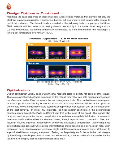
Practical Application — 0.5 W Heat Source<br />
(0.3, 1.0 & 2.0 W/m-K)<br />
Top<br />
Max at 210°F (99°C) Max at 182°F (83°C) Max at 155°F (68°C)<br />
Bottom<br />
Max at 200°F (93°C) Max at 170°F (77°C) Max at 138°F (56°C)<br />
FR4<br />
91ML<br />
92ML<br />
Heat spreading associated with 92ML is related to<br />
higher TCxy vs TCz (2X)<br />
Optimization<br />
Design optimization usually begins with thermal modeling tools to identify hot spots or other issues.<br />
There are several good software packages on the market today that can help designers understand<br />
the effects and trade-offs of the various thermal management tools. This can be time consuming and<br />
requires a good understanding of the model limitations to fully translate the results into practice.<br />
Un<strong>for</strong>tunately most modeling software assumes isotropy which may result in over or underestimation<br />
of the heat removal. In most PCB materials, the heat transfer coefficient in the perpendicular<br />
direction (down through the PWB) is different from that in the plane of the board. The models also<br />
rarely account <strong>for</strong> potential issues, complications or variation in materials, fabrication or assembly.<br />
Interfaces interfere with the heat transfer mechanism, through imperfections in conduction. This often<br />
results in reduced efficiency in heat transfer and results in excessive temperatures. Addressing these<br />
potential issues is generally where actual thermal testing of sub-assemblies & devices can help. Such<br />
testing can be as simple as power cycling or single point thermocouple measurements, all the way to<br />
sophisticated thermal imaging equipment. Testing can help designers further optimize their designs<br />
by identifying potential problems or lower cost substitutions, such as trade-offs in materials choice<br />
(aluminum vs copper, cast vs machined heat sinks, etc.).