ML6984, ML7984 Series 4000 Direct Coupled Valve Actuators
ML6984, ML7984 Series 4000 Direct Coupled Valve Actuators
ML6984, ML7984 Series 4000 Direct Coupled Valve Actuators

Create successful ePaper yourself
Turn your PDF publications into a flip-book with our unique Google optimized e-Paper software.
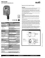
<strong>ML6984</strong>, <strong>ML7984</strong> SERIES <strong>4000</strong> DIRECT COUPLED VALVE ACTUATORSELECTRONICSERIES 90(W973, T775,H775, W7100)RW2 <strong>ML7984</strong> 3BRWT6T5ELECTRONICSERIES 90(W973, T775,H775, W7100)2 <strong>ML7984</strong> 3BRT624 VacWT51ORL1L2NOTE:POLARITY SENSITIVE,CHECK CONNECTIONSW to R, R to W2 <strong>ML7984</strong> 3BB3T6T5128 VdcRWRWT6T524 VacL1L2RWRW2 <strong>ML7984</strong> T6T524 VacORL1L2RW2 <strong>ML7984</strong> 3BRWT6T5T6T5OR28 VdcNOTE:POLARITYSENSITIVE,CHECKCONNECTIONSW to R,R to W2 <strong>ML7984</strong> 3BR T624 VacWT5T6T51T6T528 VdcL1L2OR28 VdcFUNCTIONDIP SWITCH CONFIGURATION1101Electronic <strong>Series</strong> 90<strong>Direct</strong> Acting1111Electronic <strong>Series</strong> 90Reverse Acting1 2 3 41 2 3 4On (1)Off (0)On (1)Off (0)45FUNCTION1101Electronic <strong>Series</strong> 90<strong>Direct</strong> Acting1111Electronic <strong>Series</strong> 90Reverse ActingDIP SWITCH CONFIGURATIONOn (1)Off (0)1 2 3 4On (1)Off (0)1 2 3 4451 POWER SUPPLY PROVIDES OVERLOAD PROTECTION ANDDISCONNECT MEANS.2 ALLOW UP TO 0.5 AMPS FOR EACH DEVICE. ACTUATORS ANDCONTROLLER CAN SHARE SAME TRANSFORMER PROVIDING THEVA RATING OF THE TRANSFORMER IS NOT EXCEEDED AND PROPERPHASING IS OBSERVED. DO NOT MIX A.C. AND D.C. POWER SOURCES.3 DO NOT MIX M984/6 OR MODUTROL MOTORS WITH THE <strong>ML7984</strong> INTHE SAME CIRCUITRY.4 USE CONFIGURATION DIP SWITCHES TO SELECT DEVICE FUNCTIONS:DIRECT ACTING FUNCTION (ACTUATOR STEM MOVES UPWARDS WITHSIGNAL INCREASES TO 10V/20MA) OR REVERSE ACTING FUNCTION(ACTUATOR STEM MOVES DOWNWARDS WITH SIGNAL INCREASES TO10V/20MA).5 TURN POWER OFF BEFORE SETTING ANY DIP SWITCHES.M254991234POWER SUPPLY PROVIDES OVERLOAD PROTECTION ANDDISCONNECT MEANS.ALLOW UP TO 0.5 AMPS FOR EACH DEVICE. ACTUATORS ANDCONTROLLER CAN SHARE SAME TRANSFORMER PROVIDING THE VARATING OF THE TRANSFORMER IS NOT EXCEEDED AND PROPERPHASING IS OBSERVED. DO NOT MIX A.C. AND D.C. POWERSOURCES.DO NOT MIX M984/6 OR MODUTROL MOTORS WITH THE <strong>ML7984</strong> IN THESAME CIRCUITRY.USE CONFIGURATION DIP SWITCHES TO SELECT DEVICE FUNCTIONS:DIRECT ACTING FUNCTION (ACTUATOR STEM MOVES UPWARDS WITHSIGNAL INCREASES TO 10V/20MA) OR REVERSE ACTING FUNCTION(ACTUATOR STEM MOVES DOWNWARDS WITH SIGNAL INCREASES TO10V/20MA).Fig. 15. <strong>ML7984</strong> with Common Transformer, IndividualControllers.5TURN POWER OFF BEFORE SETTING ANY DIP SWITCHES.M25500Fig. 16. <strong>ML7984</strong> with Individual Transformers, CommonController.95C-10939—09 8
<strong>ML6984</strong>, <strong>ML7984</strong> SERIES <strong>4000</strong> DIRECT COUPLED VALVE ACTUATORSOPERATIONEach time actuator terminals T5 and T6 are (re)powered, themicroprocessor will cycle the valve through a full stroke tocalibrate its position. Any stroke between 1/2 in. (13 mm) and 1in. (25 mm) will be divided into 30 equal steps. Run time isproportional to stroke length and power supply voltage. Theactuator will also slow down as the valve closes off the seat.The LED lights when terminals T5 and T6 are powered, andflashes when the actuator is in motion. T5 is connected toTerminal R in <strong>ML6984</strong> and to Terminal W in <strong>ML7984</strong>.NOTE:Initial calibration does not apply to <strong>ML6984</strong> installedfor 3-wire control or installed for 5-wire control withoutthe 272630D position feedback/auxiliary switch module.Span and start positions will need to be set duringcontroller set-up. See <strong>ML6984</strong> Operation 3-wire,below. <strong>ML7984</strong> always conducts a self-calibrationsequence when (re)powering up.<strong>ML7984</strong> OperationThe microprocessor responds to the signal across the inputterminals based on the configuration DIP switch settings.When correctly connected to the actuator, a control signalbetween signal input terminals is converted to a digital run timeand compared to pulse counts from the first gear in the geartrain. When these counters are equal, the drive motor anddrive shaft are stationary.As long as the value of the controlled medium remains at thecontroller setpoint, the control loop circuit is in balance, and theactuator does not run. When the controller set point orcontrolled temperature changes, the controller output voltageis changed, causing the counters to differ. As the actuatormoves in the direction to correct the difference, the countersincrement or decrement, and stop the actuator when the inputand gear counts agree.At the end of the valve stroke, the actuator develops thenecessary force for positive valve close-off. The motor stopsautomatically when the motor draws a predetermined currentwhich corresponds to a force level. The digital counters arereset and calibrated at each end of stroke.Modulating actuators will automatically travel to the positioncorresponding to analog input signal following the selfcalibrationcycle.CAUTIONDisconnect power supply before beginninginstallation to prevent electrical shock andequipment damage.All wiring must comply with applicable local electricalcodes, ordinances, and regulations.Make certain that the voltage and frequency of thepower supply correspond to the rating of the device.DO NOT electrically operate the MLx984 actuatorbefore assembly to the valve because damage notapparent to the installer may occur.DO NOT connect 24 Vac between any <strong>ML7984</strong> signalinput terminals. DEVICE FAILURE WILL RESULT.NOTE:1. The <strong>ML7984</strong> must be field configured with the DIPswitches which are located beside the terminalblock. See wiring diagrams for details. Turn poweroff before setting any DIP switches.2. There is a 1.5 second delay in actuator responseto every signal change. This occurs to screen outelectrical noise.3. For proper operation, voltage on the T5 and T6must not be less than 22 Vac or 24 Vdc during runningor force generating stages. Increase transformerVA rating or use a model with betterregulation if voltage drops below 22 Vac when thevalve is closing off.<strong>ML6984</strong> Floating Operation, 5-WireThe motor is controlled by a microprocessor. Connecting B toR for 1/10 second or longer tells the microprocessor to causethe actuator to drive upwards. Connecting W to R will causethe actuator to drive downwards. For “floating” control, theactuator will remain in the last position when there is noconnection to R.At the end of the valve stroke, the actuator will develop thenecessary force for positive valve close-off. As forces aredeveloped, the current to the motor increases. Themicroprocessor stops the actuator automatically when motorcurrent and force reaches the factory-calibrated level.NOTE:There must be at least 1.5 second delay betweensuccessive floating input signals. The actuator willignore floating signals during calibration cycle anddoes not remember any pulses sent during thisperiod. The controller may need to run through itsown calibration cycle before use.<strong>ML6984</strong> Operation, 3-Wire<strong>ML6984</strong> may be installed like a conventional (non-electronic)floating actuator. The interface electronics are powered at thesame time as the motor. Pulses must be at least 100 ms longwith a delay of at least 1500 ms between pulses. When<strong>ML6984</strong> is not powered between terminals T6 and T5/R, selfcalibrationwill not occur. The controller must drive the valvethrough a cycle manually to calibrate stroke to the controller.NOTE:The 272630D position feedback/auxiliary switch modulecannot be used with <strong>ML6984</strong> 3-wire installation.The 272630D requires continuous power.<strong>ML6984</strong> XL10 ControllerCompatibilityXL10 controllers are designed to work with constant-speedactuators. <strong>ML6984</strong> actuators use direct current motors whichvary their speed as the valve seats or if power supply voltage isnot consistent. <strong>ML6984</strong> actuators in 5-wire mode offer 30discrete positions only. To minimize potential valve positiondrift, XL10 controllers should use the 3-wire installation and beprogrammed for a daily valve exercise cycle.<strong>ML6984</strong> On-Off OperationFor on-off operation, <strong>ML6984</strong> requires a 24 Vac SPDT contact.An interface relay such as RA889 is required to power theanticipator heater of an electromechanical thermostat such asT87F (See Fig. 17).9 95C-10939—09
<strong>ML6984</strong>, <strong>ML7984</strong> SERIES <strong>4000</strong> DIRECT COUPLED VALVE ACTUATORSTHERMOSTAT WIRING TERMINALS1L1L2RW21K1K1B R WT5 T6<strong>ML6984</strong>TH5110DTH6110D RcRYC4WO/BG231 POWER SUPPLY. PROVIDE DISCONNECT MEANS ANDOVERLOAD PROTECTION AS REQUIRED.2 SET HEATING ANTICIPATOR TO MATCH CURRENT DRAW OFRELAY 1K. DO NOT ROUTE RELAY CONTACTS THROUGHTHERMOSTAT.M25501Fig. 17. <strong>ML6984</strong> with Honeywell T87F RoundThermostat.1<strong>ML6984</strong>POWER TO OPENB W R AND POWER TOCLOSET6 T5 5MOTOR OR VALVE(SERIES 20)RPOWER SUPPLY. PROVIDE DISCONNECT MEANS AND OVERLOADPROTECTION AS REQUIRED.C1L1(HOT)L2If connecting the <strong>ML6984</strong> directly to a T87F with a <strong>Series</strong> 20sub-base, clip out the cooling anticipation resistor on the subbasebetween terminals R c and Y. This is needed for electricalcompatibility with <strong>ML6984</strong> but may result in wider roomtemperature swings due to the loss of anticipation.REPLACEMENT NOTES1124Vac24VacHEATING ONLYRRFig. 18. <strong>ML6984</strong> with Honeywell T87K RoundThermostat.M25502See Fig. 19, if connecting TH5110D or TH6110D FocusPROthermostats to <strong>ML6984</strong>. Configure the thermostats for <strong>Series</strong>20 operation.WYCOOLING ONLYWYT6T5CBWR<strong>ML6984</strong>T6T5CBWR<strong>ML6984</strong>1 CLASS 2 TRANSFORMER. PROVIDE DISCONNECT MEANS ANDOVERLOAD PROTECTION AS REQUIRED.UPDOWNUPDOWN2345FACTORY INSTALLED JUMPER.OPTIONAL 24 VAC COMMON CONNECTION.CONFIIGURE SYSTEM TYPE TO HEAT ONLY IN THE INSTALLER SETUP.TERMINALS R AND T5 ARE INTERNALLY CONNECTED.M25503Fig. 19. <strong>ML6984</strong> with FocusPro Electronic Thermostat.To Replace ML784 or ML9841. The old ML784 or ML984 actuators cannot be used withnew <strong>ML7984</strong> valve actuators in the same circuitry,unless the old models are each powered by their owntransformer to prevent cross-talking.2. The <strong>ML7984</strong> is a direct replacement for all old ML784and ML984, except:a. When replacing the old reverse acting models, thesignal input wires to the new devices no longer needto be reversed. Just follow the terminal polarity designationsand DIP switch settings.b. When replacing the old actuator which has an Electronic<strong>Series</strong> 90 “Supermod” controller - e.g.: T775,W973, H775, or W7100 - the old interface resistormust be removed. The <strong>ML7984</strong> <strong>Series</strong> <strong>4000</strong> will workdirectly with the controller without the external 240ohm resistor.c. When replacing the old ML784 (mA model) in multiple-actuatorinstallations, resistor(s) will be needed.Use Resistor Kit (part no. 272822) and set DIPswitches accordingly. See Figures 17 and 18.To Replace ML684A1. The new <strong>ML6984</strong> is a direct replacement for the oldML684A in single actuator or parallel multiple actuatorshook-up. The old and new actuators can be mixed in thesame electrical circuit. For multiple actuators controlledby a common controller in parallel, these actuators mustbe wired so that they all travel in the same direction.2. When replacing the ML684A1009 (80 lbf) with this new<strong>ML6984</strong> on the V5045 valve, the installed valve adaptor(part no. 272629A) on the valve stem and actuatorassembly is still needed.95C-10939—09 10
<strong>ML6984</strong>, <strong>ML7984</strong> SERIES <strong>4000</strong> DIRECT COUPLED VALVE ACTUATORSNOTE:The 272630D position feedback/auxiliary switch modulecannot be used with <strong>ML6984</strong> 3-wire installation.The 272630D requires continuous power.To Replace ML68741. The <strong>ML6984</strong> is a direct replacement for the old ML6874in single actuator hook-up.2. For parallel, multiple ML6874 actuators applications, anisolation relay must be used. The isolation relay contactsshould be placed in the new <strong>ML6984</strong> actuator signalinput “W” and “B” circuit.To Replace Line Voltage AuxiliarySwitchesThese accessories are no longer available. Replace the oldactuator with new model and 272630D position feedback/auxiliary switch module.Operate an external relay, such as R8845U, using theadjustable SPDT pilot duty output on the 272630D.If a second, independent output switch is needed, wire the 2-10 Vdc position feedback signal to an Approved, adjustable,voltage-controlled relay.CHECKOUT<strong>ML7984</strong>1. Make sure the valve stem is completely screwed into theactuator drive shaft with no threads showing beforeapplying power.2. Make sure the valve stem is locked in place with the setscrew.3. Make sure the Configuration DIP switches are set correctly.4. With 24 Vac or 28 Vdc power source connected to T5and T6, actuator operation can be verified by connectingappropriate control signal (<strong>Series</strong> 70/90) from controllerto the signal input terminals (Figures 8 thru 16). Fordirect acting: A modulating action can be obtained byincreasing the control signal. The actuator will travel fromstem down to stem up. On signal failure (disconnected/no signal), actuator defaults to closed position. Forreverse acting: Decreasing controller signal will driveactuator from full stem down to full stem up. On signalfailure (disconnect/no signal), actuator defaults to openposition.5. Operate the system (valve, actuator, and controller) forseveral cycles to ensure proper installation.6. When checkout is complete, return the controller to thedesired setting.NOTE:1. The Device will ignore any input changes until ithas completed its repositioning relative to the initialsignal input.2. 272630D position feedback/auxiliary switch moduleis inactive during self-calibration.<strong>ML6984</strong>: 5-Wire Installation1. Make sure the valve stem is completely screwed into theactuator drive shaft with no threads showing beforeapplying power.2. Make sure the valve stem is locked in place with the setscrew.3. Connect 24 Vac or 28 Vdc power to T5 and T6.4. Jumper R and B. The valve stem should move up.5. Jumper R and W. The valve stem should move down.6. For Floating operation, open R connection <strong>Valve</strong> stemshould remain in position.7. Re-connect all control wiring.8. Operate the system (valve, actuator, and controller) forseveral cycles to ensure proper installation.9. When checkout is complete, return the controller to thedesired setting.<strong>ML6984</strong>: 3-Wire Installation1. Make sure the valve stem is completely screwed into theactuator drive shaft with no threads showing beforeapplying power.2. Make sure the valve stem is locked in place with the setscrew.3. Connect 24 Vac to T6.4. Manually override the controller to signal the actuator toopen/close for a few cycles to ensure proper installation.5. When checkout is complete, return the controller to thedesired setting.TROUBLESHOOTINGSymptom Possible Causes Actions<strong>Valve</strong> seat leaks or will not closeproperlyWrong actuator used and/or system headpressure too highActuator not properly installedIncorrect DIP switch settings1) Check valve close-off rating2) Check voltage at actuator terminalsEnsure valve stem is fully threaded into brass drive shaft andlocked in place with the set screwCheck against Product Instruction SheetNoisy Motor Bearing failed due to overheat 1) Check for excessive temperature and replace complete actuator2) Use high temperature kit (43196000-001)Brushes worn outCheck for excessive cycling and replace actuator11 95C-10939—09
<strong>ML6984</strong>, <strong>ML7984</strong> SERIES <strong>4000</strong> DIRECT COUPLED VALVE ACTUATORSMotor overheats/smoke/componentburn-outML will not respondVdc/mA signal drops whenconnected to MLActuator yoke corrodesSymptom Possible Causes ActionsFloating Actuator position “drifts”when used with building automationsystemCurrent sensing circuit failed or electroniccomponents failedLED (on):Incorrect DIP switch settingsNo control signal presentIncorrect wiring connectionsInternal time delayLED (off):No or low power supplyError mode (gearbox damage)<strong>ML7984</strong> in mA mode with voltage inputSignal degradation due to incompatible loadimpedanceGalvanic reaction from dissimilar metals ifSS U-bolt used with aluminum yokeMismatch between actuator resolution(30 steps) and BAS controllerReplace actuator. Make sure:1) Correct actuator used2) Properly installed3) Do not operate actuator before mounting on valve supply4) Proper voltage supplyCheck against Product Instruction SheetCheck controllerCheck against Product Instruction SheetAllow at least 1/2 - 1 second for the ML to respondCheck voltage on T5 and T6 terminals1) Check power supply2) Check calibration cycle3) <strong>Valve</strong> stroke length less than 1/2 in. or greater than 1-1/4 in.4) Reset device by a momentary disconnect of power at T5 and T6Change DIP switch settingOutput and ML input impedance specificationsReplace U-bolt with galvanized U-bolt and nuts1) Read actual valve position using 272630D feedback module2) Rewire actuator for 3-wire control3) Program daily valve reset.TYPICAL SPECIFICATIONS<strong>Valve</strong> <strong>Actuators</strong> shall mount directly to the bonnet of the valve,and shall be self-contained and self adjusting.<strong>Direct</strong> coupled valve actuators shall be 24° Vac or 28° Vdc power, available with floating or modulating control signal inputs.Actuator shall be usable with common power supply for multiple actuators and controllers.Position feedback voltage/pilot duty auxiliary switch kit,mounting adaptor, high temperature kits, and resistor kits formultiple actuator application shall be optional accessories fordirect coupled valve actuators.<strong>Direct</strong> coupled valve actuators shall have a minimumperformance rating of 50,000 full stroke cycles plus 1,000,000repositions documented in the product literature.<strong>Direct</strong> coupled valve actuators shall be manufactured by thesame company as manufacturers of the valves.Automation and Control SolutionsHoneywell International Inc.1985 Douglas Drive NorthGolden Valley, MN 55422® U.S. Registered Trademark© 2011 Honeywell International Inc.95C-10939—09 K.K. Rev. 06-11Printed in U.S.A.