VeeCAN 320 VEM Manual - Veethree Instruments
VeeCAN 320 VEM Manual - Veethree Instruments
VeeCAN 320 VEM Manual - Veethree Instruments
- No tags were found...
You also want an ePaper? Increase the reach of your titles
YUMPU automatically turns print PDFs into web optimized ePapers that Google loves.
<strong>VeeCAN</strong> is a Registered Trademark of <strong>Veethree</strong> Electronics and Marine LLC
TABLE OF CONTENTS1.................. Introduction.............................................................................51.1............... Getting Started........................................................................71.2............... Preferred Screen Store......................................................... 81.3............... Inputs........................................................................................ 91.4............... Software...................................................................................92.................. General Operation................................................................102.1............... Keys 1 to 4 Operation...........................................................102.2............... Adjusting Lighting and Contrast........................................ 113.................. Display Screens................................................................... 123.1............... Quad Analog View (Screen 1)............................................ 12Quad Digital View (Screen 2)............................................. 143.2............... Single Analog View (Screen 3).......................................... 154.................. Alarm Functionality (Screen 4).......................................... 175.................. Menu Screens...................................................................... 205.1............... Top level menu......................................................................205.2............... Settings Menu and Sub-menus......................................... 205.3............... System Menu and Sub-menus.......................................... 215.4............... Data Base Viewer / Display Mapping.............................. 226.................. I/O Settings........................................................................... 236.1............... Analog Inputs....................................................................... 246.2............... Digital Inputs........................................................................ 25
TABLE OF CONTENTS cont.6.3............... Internal Voltage....................................................................266.4............... Internal Engine Hours..........................................................266.5............... Outputs................................................................................... 276.6............... Alarms.................................................................................... 287.................. J1939 PGNs Supported........................................................298.................. Database List and PGNs..................................................... 329.................. Communicarions.................................................................. 3710................ Accessories.......................................................................... 38
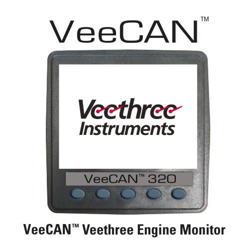
1. INTRODUCTIONThese pages provide operatinginstructions for the <strong>Veethree</strong>Engine Monitor which displaysJ1939-compatible engine/transmission data. Please readthrough the guide before use.The <strong>Veethree</strong> Engine Monitor(<strong>VEM</strong>) user-configurableapplication software createsgraphical instrument clustersto display parameters andalarms - providing users witha timesaving solution forTM<strong>VeeCAN</strong> <strong>320</strong>introducing equipment incorporating higher degrees of electronicdisplay and control.We hope that you will be pleased with this product and that you willhave many years of trouble free operation. If you have any problems orideas for improvement then we would like to hear from you.5
For more information please see the web site: www.v3instruments.comor contact us at: sales@veethree.comThe <strong>VEM</strong> software runs on a <strong>VeeCAN</strong> display with five soft keys,providing a flexible and intuitive Human-Machine Interface (HMI). The5 soft keys access a graphical menu structure that uses standard andeasily-understood icons to indicate the key’s current function. Thisenables the operator to select the required engine/transmission dataand display it in the following formats:• Analog gauges• Digital values• Current alarm messagesAdditionally, various diagnostic screens are available, allowingdetailed investigation of the engine and transmission data stream.The underlying structure of the <strong>VEM</strong> and its interaction with the softkeys are further explained in the following section. By accessing theConfiguration menu, users can customize some of the displayed datato show, for example, metric or imperial units, and various parameterssuch as the full-scale reading of gauges.6
1.1 Getting StartedPRIMARY CONNECTOR1GNDGROUNDCONNECTORPIN OUT2PWRPOWER (10-30V DC).SUPPLY SHOULD BE PROTECTED BY500mA - RATED CIRCUIT BREAKER/FUSE673RLA1RELAY/SOLENOID OUTPUT 14RLA2RELAY/SOLENOID OUTPUT 25CAN2 (-)ISOLATED CAN SUPPLY (-)6CAN2 (+)ISOLATED CAN SUPPLY (+)7CAN2HISOLATED CAN DATA H1 1289CAN2LRLA3ISOLATED CAN DATA LRELAY/SOLENOID OUTPUT 310RLA4RELAY/SOLENOID OUTPUT 411CAN1LPRIMARY CAN DATA L12CAN1HPRIMARY CAN DATA HSECONDARY CONNECTOR1 AN1SENSOR 1 ANALOG INPUTCONNECTORPIN OUT2 AN2SENSOR 2 ANALOG INPUT3 AN3SENSOR 3 ANALOG INPUT12145AN4AN5SENSOR 4 ANALOG INPUTSENSOR 5 ANALOG INPUT6AN6SENSOR 6 ANALOG INPUT7AN7SENSOR 7 ANALOG INPUT8DIG1DIGITAL INPUT/FLOW SENSOR 19DIG2DIGITAL INPUT/FLOW SENSOR 27610TACHTACHOMETER INPUT11RS232RXRS232 RECEIVE12RS232TXRS232 TRANSMITOnce Power and Ground are connected the unit will power upautomatically.7
[Splash Screen]81.2 Preferred Screen StoreThe <strong>VEM</strong> automatically stores the current screen as the user’spreferred page, after a delay of approximately 15 seconds (if no buttonsare pushed). On the next power-up the display will start with the splashscreen, and then go to the last stored screen. Note: Selecting RestoreDefaults on the Systems sub-menu of Configuration will set screen 1as the default display.
1.3 InputsAnalog Inputs (x7) - Each input can be selected as 0-2.5V DC, 0-10V DCor 0-1K ohms.Switch Inputs (x2) - Switch contact to ground or open collector typesensor. Max frequency 50 Hz.Tachometer Input - Magnetic type or hall effect (and similar) withpush-pull output. Max frequency 5 KHz.Relay/Solenoid Outputs (x4) - Open collector output, suitable for 0.5Acontinuous load.1.4 SoftwareThe <strong>VeeCAN</strong> software can be updated or custom software can beinstalled using a USB flash drive. While the <strong>VeeCAN</strong> is powered upplug the flash drive containing the software into the USB port locatedon the back of the <strong>VeeCAN</strong>. Software will be installed automatically.Once the <strong>VeeCAN</strong>’s backlight starts to flash, remove the flash drivefrom the USB port. The <strong>VeeCAN</strong> will restart and run with the newsoftware.9
2. GENERAL OPERATIONTM<strong>VeeCAN</strong> <strong>320</strong>2.1 Keys 1 to 4 OperationThere are 4 main user screens accessed via the first four keys. Thekeys have icons to represent the screen view types, as follows.Key 1 is a quad gauge view, Key 2 is a quad digital data view and key3 is a single analog gauge view. Key 4 is used to access the alarmscreen.10
TM<strong>VeeCAN</strong> <strong>320</strong>2.2 Adjusting Lighting and ContrastPressing Key 5 (the right-hand key) when the menu icons are not beingdisplayed brings up the lighting menu. The LCD has a number of backlightinglevels that allow the display brightness and keypad brightnessto be adjusted. The appropriate level is selected by pressing keys1 or 2 to decrease or increase the illumination level of the LCD. Thekeypad brightness is adjusted in the same manner.11
3. DISPLAY SCREENS3.1 Quad Analog View (Screen 1)This screen is a configurable quad analoggauge view. There is an option to have upto 4 quad analog views (so a total of 16gauges can be selected). The number ofquad views is adjustable between 1 and 4(default). The data that can be chosen isalso configurable (an option in theDBViewer screen).TM<strong>VeeCAN</strong> <strong>320</strong>Note. If a parameter is not availablefrom the engine/transmission, it will notbe possible to select it. If the parameterbecomes unavailable while in view,‘---’ is displayed.To adjust the contents of the quadscreens - first press any of the first fourkeys to raise the button bar and thanpress key 5 to enable the cycling throughof all the display parameters.TM<strong>VeeCAN</strong> <strong>320</strong>12
Data Available for Quad Screens (both analog and digital views)db_0190_ENGINE_RPM,db_0110_ENGINE_COOLANT_TEMP,db_0167_ALTERNATOR_POTENTIAL,db_0114_NET_BATTERY_CURRENT,db_0109_COOLANT_PRESSURE,db_0100_ENGINE_OIL_PRESSURE,db_0127_TRANS_OIL_PRESSURE,db_0173_EXHAUST_GAS_TEMP,db_0105_INTAKE_MANIFOLD_1_TEMP,db_0091_ACCELERATOR_POSITION,db_0523_CURRENT_GEAR,db_1387_AUXILIARY_PRESSURE_1,db_0174_FUEL_TEMP,db_0052_ENGINE_INTERCOOLER_TEMP,db_0111_COOLANT_LEVEL,db_0172_AIR_INLET_TEMP,db_0107_AIR_FILTER_1_DIFF_PRESS,db_0513_ACTUAL_ENGINE_PERCENT_TORQUE,db_1036_TRIP_ENGINE_RUNNING_TIMEdb_0084_0517_NAV_WHEEL_BASED_VEHICLE_SPEED,db_0168_0158_ELEC_BAT_POTENTIAL,db_0115_ALTERNATOR_CURRENT,db_0102_BOOST_PRESSURE,db_0094_FUEL_DELIVERY_PRESSURE,db_0247_TOTAL_ENGINE_HOURS,db_0177_TRANS_OIL_TEMP,db_0175_ENG_OIL_TEMP_1,db_0092_TORQUE_USE_AT_RPM,db_0524_SELECTED_GEAR,db_0441_AUXILIARY_TEMP_1,db_0975_EST_PERCENT_FAN_SPEED,db_0176_TURBO_OIL_TEMP,db_0098_ENGINE_OIL_LEVEL,db_0108_BARO_PRESSURE,db_0106_AIR_INLET_PRESSURE,db_0183_FUEL_RATE,db_1029_TRIP_AVERAGE_FUEL_RATE,db_0096_FUEL_LEVEL13
Quad Digital View (Screen 2)This screen is a configurable quad analoggauge view. There is an option to have upto 4 quad analog views (so a total of 16gauges can be selected). The number ofquad views is adjustable between 1 and 4(default). The data that can be chosen isalso configurable (an option in theDBViewer screen).Note. If a parameter is not aveilablefrom the engine/transmission, it will notbe possible to select it. If the parameterbecomes unavailable while in view,‘---’ is displayed.To adjust the contents of the quadscreens - first press any of the first fourkeys to raise the button bar and thanpress key 5 to enable the cycling throughof all the display parameters.TM<strong>VeeCAN</strong> <strong>320</strong>TM<strong>VeeCAN</strong> <strong>320</strong>14
3.2 Single Analog View (Screen 3)This screen is a single analog gauge view. The data selected is alsoconfigurable (an option in the DBViewer screen).Note. If a parameter is notavailable from the engine/transmission, it will not bepossible to select it.If the parameter becomesunavailable while in view,‘- - -’ is displayed.TM TM<strong>VeeCAN</strong> <strong>320</strong>15
Data Available for Single Screendb_0190_ENGINE_RPM,db_0100_ENGINE_OIL_PRESSURE,db_0102_BOOST_PRESSURE,db_0167_ALTERNATOR_POTENTIAL,db_0114_NET_BATTERY_CURRENT,db_0094_FUEL_DELIVERY_PRESSURE,db_0177_TRANS_OIL_TEMP,db_0175_ENG_OIL_TEMP_1,db_0110_ENGINE_COOLANT_TEMP,db_0183_FUEL_RATE,db_0168_0158_ELEC_BAT_POTENTIAL,db_0115_ALTERNATOR_CURRENT,db_0109_COOLANT_PRESSURE,db_0127_TRANS_OIL_PRESSURE,db_0173_EXHAUST_GAS_TEMP,db_0105_INTAKE_MANIFOLD_1_TEMP16
4. ALARM FUNCTIONALITY(Screen 4)The <strong>VEM</strong> supports active faults received from DM1 messages.When an active/current alarm is received, a flashing pop-up windowappears overlaid on the active screen, showing details of the currentalarm. When an activealarm is received, the<strong>VEM</strong> activates its internalsounder.The alarm list is accessedby pressing any keywhile an alarm pop-up isdisplayed, or by pressingany of the first 4 keys toshow the button bar, andthen key 4. This screendisplays all current activealarms. Alarms not yetacknowledged are shownTM<strong>VeeCAN</strong> <strong>320</strong>Alarm Pop-up Screen17
in black text on a red background. Alarms already acknowledged areshown in white text on black. If the engine hours data is available, thelist indicates when the alarm was initiated.When first entering the alarm screen, the list automatically displaysthe most recent alarm. The list can be scrolled using keys 1 and 2. Thisscreen cannot be exited until all alarms have been acknowledged bypressing key 3. Alarm messages are automatically cleared from the listwhen no longer receivedby the <strong>VEM</strong>.TM<strong>VeeCAN</strong> <strong>320</strong>ENGINE SERVICEWARNING. In theConfiguration menu, userscan set the engine serviceinterval in hours. Whenthe <strong>VEM</strong> determines anengine service is due,it will display SERVICEREQUIRED on the splashscreen that appears atpower-up.18Alarm Screen Before Alarm Acknowledge.
DATA COMMUNICATIONSFAILURE. If the <strong>VEM</strong> cannotdetect engine/transmission databroadcasts, a pop-up windowwith a data communicationsfailure warning icon willappear and flash. Once engine/transmission data is detected thewarning disappears and normaldata display resumes.TM<strong>VeeCAN</strong> <strong>320</strong>Typical Alarm Screenafter Alarm Acknowledge19
5. MENU SCREENS5.1 Top Level MenuTM<strong>VeeCAN</strong> <strong>320</strong>TM<strong>VeeCAN</strong> <strong>320</strong>TMTM<strong>VeeCAN</strong> <strong>320</strong><strong>VeeCAN</strong> <strong>320</strong>TM<strong>VeeCAN</strong> <strong>320</strong>5.2Settings Menuand Sub-menusTM<strong>VeeCAN</strong> <strong>320</strong>TM<strong>VeeCAN</strong> <strong>320</strong>TM<strong>VeeCAN</strong> <strong>320</strong>20
5.3 System Menu and Sub-menusTM<strong>VeeCAN</strong> <strong>320</strong>TM<strong>VeeCAN</strong> <strong>320</strong>TM<strong>VeeCAN</strong> <strong>320</strong>21
5.4 Data Base Viewer / Display MappingTM<strong>VeeCAN</strong> <strong>320</strong>TM<strong>VeeCAN</strong> <strong>320</strong>22LEFT: This screen can be adapted to allow the data mapping / filter foreach of the three data views. The operator can check boxes for eachitem they want to appear on each of the standard views (Quad andSingle). Key 1 and Key 2 are page up/down respectively. Key 3 movesdown the list one item and Key 4 is to edit the settings of the viewfilters. The red box indicates that the option is not available.RIGHT: This shows the screen in “edit” mode where the highlighted item(in RED) can be chosen to be viewed in the quad or the single view orin both or in neither.
6. I/O SETTINGSTM<strong>VeeCAN</strong> <strong>320</strong>TM<strong>VeeCAN</strong> <strong>320</strong>TM<strong>VeeCAN</strong> <strong>320</strong>LEFT: Access this screen through the settings in the Configuration Menu.CENTER: This screen is used to access inputs, outputs, alarms and enginepresets. Engine presets option is used to reset the unit to factory settings.RIGHT: This screen allows for function selection for analog inputs,digital inputs, voltage and internal engine hours. Pressing Key 4 willaccess the selected pin. Please see section 1.1 pin location.23
246.1 Analog InputsTM<strong>VeeCAN</strong> <strong>320</strong>TM<strong>VeeCAN</strong> <strong>320</strong>This screen is designed for configurationof analogue pins. Use Key 1 and Key 2 tonavigate up/down. Use Key 3 and Key 4for back/forward.Signal Type - Select type of signal thesender is sending. Most analogue sendersare resistance senders.Parameter - Used to select the functionof the sender.Table - Select the resistance table ofthe sender used.Example: This is an example of a 0-80 PSI oilpressure sender using the 240-33 ohm resistancerange. The prefix:L - LevelP - PressureTF - Temperature (F)TC - Temperature (C)NOTE: The input and output windows will showreadings when sender is connected.
5.2 Digital Inputs (8-10)TM<strong>VeeCAN</strong> <strong>320</strong>This screen is designed for configuration of digital input signals.NOTE: Only pin 10 can be used as a tachometer signal.Signal Type - Select from a digital count, frequency, period or level.Parameter - Used to select the function.Table - Not selectable.Signal Gain and Signal Offset - used to adjust accuracy of the readings.25
6.3 Internal VoltageThere is no pin for voltage, the voltagereading is extracted from the supply voltageof the <strong>VeeCAN</strong> unit.TM<strong>VeeCAN</strong> <strong>320</strong>6.4 Internal Engine HoursThis screen is used to set up the internalengine hour meter.TM<strong>VeeCAN</strong> <strong>320</strong>26
6.5 OutputsTM<strong>VeeCAN</strong> <strong>320</strong>TM<strong>VeeCAN</strong> <strong>320</strong>LEFT: This screen is used to turn ON and OFF relay alarms, if wired intothe associated pins of the <strong>VeeCAN</strong> unit. These are open connectoroutputs, suitable for 0.5A continuous loads.RIGHT: Use KEY 1 and KEY 2 to navigation up/down, use KEY 4 toselect between “Alarm” and “Output Off”.27
6.6 AlarmsTM<strong>VeeCAN</strong> <strong>320</strong>TM<strong>VeeCAN</strong> <strong>320</strong>LEFT: This screen is used to access all alarms. That can be set for theanalog pins, digital pins, internal voltage and internal engine hours.RIGHT: All inputs can have a LOW and HIGH alarm function. Use thresholdfunction to set the alarm values.28
7. J1939 PGNs SUPPORTED// PGN 56832 (0xDE00) (R) Reset// PGN 61442 (0xF002) Electronic Transmission Controler 1// PGN 61443 (0xF003) Electronic Engine Controller 2// PGN 61444 (0xF004) Electronic Engine Controller 1// PGN 61445 (0xF005) Electronic Transmission Controller 2// PGN 61448 (0xF008) Hydraulic Pressure Governor Info// PGN 64891 (0xFD7B) (R) Aftertreatment 1 Service// PGN 64892 (0xFD7C) (R) Particulate Trap Control 1// PGN 64947 (0xFDB3) Aftertreatment 1 Outlet Gas 2// PGN 64948 (0xFDB4) Aftertreatment 1 Intake Gas 2// PGN 65110 (0xFE56) Tank Information 1// PGN 65164 (0xFE8C) (R) Auxiliary Analog Information// PGN 65169 (0xFE91) Fuel Leakage// PGN 65178 (0xFE9A) Turbocharger Information 2// PGN 65187 (0xFEA3) Exhaust Port Temperature 129
PGN 65188 (0xFEA4) Engine Temperature 2// PGN 65198 (0xFEAE) Air Supply Pressure// PGN 65200 (0xFEB0) Trip Time Information 2// PGN 65201 (0xFEB1) ECU History// PGN 65203 (0xFEB3) Fuel Information (Liquid)// PGN 65213 (0xFEBD) Fan Drive// PGN 65243 (0xFEDB) Engine Fluid Level/Pressure 2// PGN 65245 (0xFEDD) Turbocharger// PGN 65246 (0xFEDE) Air Start Pressure// PGN 65247 (0xFEDF) Electronic Engine Controller 3// PGN 65248 (0xFEE0) Vehicle Distance// PGN 65252 (0xFEE4) (R) Shutdown// PGN 65253 (0xFEE5) Engine Hours, Revolutions// PGN 65255 (0xFEE7) Vehicle Hours// PGN 65257 (0xFEE9) Fuel Consumption (Liquid)30
PGN 65262 (0xFEEE) Engine Temperature 1// PGN 65263 (0xFEEF) Engine Fluid Level/Pressure 1// PGN 65265 (0xFEF1) (R) Cruise Control/Vehicle Speed// PGN 65266 (0xFEF2) (R) Fuel Economy (Liquid)// PGN 65269 (0xFEF5) Ambient Conditions// PGN 65270 (0xFEF6) (R) Inlet/Exhaust Conditions 1// PGN 65271 (0xFEF7) (R) Vehicle Electrical Power 1// PGN 65272 (0xFEF8) Transmission Fluids 1// PGN 65276 (0xFEFC) Dash Display31
8. DATABASE LIST AND PGNsDATABASE NAME Description J1939 PGNdb_46_PNEUMATIC_SUPPLY_PRESSURE Pneumatic Supply Pressure FEAEdb_0051_THROTTLE_POSITION Throttle Position FEF2db_0052_ENGINE_INTERCOOLER_TEMP Engine Intercooler Temperature FEEEdb_0082_AIR_START_PRESSURE Air Start Pressure FEDEdb_0084_0517_NAV_WHEEL_BASED_VEHICLE_SPEEDVehicle SpeedFEF1db_0091_ACCELERATOR_POSITIONAcceleration PositionF003db_0092_TORQUE_USE_AT_RPM Torque at RPM F003db_0094_FUEL_DELIVERY_PRESSURE Fuel Delivery Pressure FEEFdb_0096_FUEL_LEVEL Fuel Level FEFCdb_0098_ENGINE_OIL_LEVELEngine Oil LevelFEEFdb_0100_ENGINE_OIL_PRESSURE Oil Pressure FEEFdb_0102_BOOST_PRESSURE Turbo Pressure FEF6db_0103_TURBO_1_SPEED Turbo 1 Speed FEDDdb_0105_INTAKE_MANIFOLD_1_TEMP Intake Manifold Temperature FEF6db_0106_AIR_INLET_PRESSURE Air Inlet Pressure FEF6db_0107_AIR_FILTER_1_DIFF_PRESSAir Filter PressureFEF6db_0108_BARO_PRESSUREBaro PressureFEF5db_0109_COOLANT_PRESSURE Ext Coolant Pressure FEEF32CONTINUES ON NEXT PAGE
DATABASE NAME Description J1939 PGNdb_0110_ENGINE_COOLANT_TEMP Coolant Temp FEEEdb_0111_COOLANT_LEVEL Coolant Level FEEFdb_0114_NET_BATTERY_CURRENT Battery Current FEF7db_0115_ALTERNATOR_CURRENT Alternator Current FEF7db_0123_CLUTCH_PRESSUREClutch PressureFEE8db_0127_TRANS_OIL_PRESSURE Trans Oil Pressure FEF8db_0157_INJ_METERING_RAIL_1_PRESSURE Inj Met Rail 1 Pressure FEDBdb_0161_INPUT_SHAFT_SPEEDInput Shaft SpeedF002db_0164_INJECTION_CONTROL_PRESSURE Injection Control Pressure FEDBdb_0167_ALTERNATOR_POTENTIAL, Alternator Voltage FEF7db_0168_0158_ELEC_BAT_POTENTIAL Voltage FEF7db_0172_AIR_INLET_TEMP Air Inlet Temperature FEF5db_0173_EXHAUST_GAS_TEMP Exhaust Temperature FEF6db_0174_FUEL_TEMP Fuel Temperature FEEEdb_0175_ENG_OIL_TEMP_1Engine Oil TemperatureFEEEdb_0176_TURBO_OIL_TEMPTurbo Oil TemperatureFEEEdb_0177_TRANS_OIL_TEMPTrans Oil TemperatureFEF8db_0182_TRIP_FUEL Trip Fuel FEE9db_0183_FUEL_RATEFuel RateFEF2CONTINUES ON NEXT PAGE33
DATABASE NAME Description J1939 PGNdb_0184_INSTANT_FUEL_ECON Instant Fuel Economy FEF2db_0185_AVG_FUEL_ECON Trip Fuel Economy FEF2db_0190_ENGINE_RPM Engine RPM F004db_0191_OUTPUT_SHAFT_SPEED Output Shaft Speed F002db_0244_TRIP_DISTANCETrip DistanceFEE0db_0245_TOTAL_VEHICLE_DISTANCE Total Distance FEE0db_246_TOTAL_VEHICLE_HOURS Total Vehicle Hours FEE7db_0247_TOTAL_ENGINE_HOURSEngine HoursFEE5db_0250_TOTAL_FUEL_USEDTotal FuelFEE9db_0441_AUXILIARY_TEMP_1 Auxiliary Temp 1 FE8Cdb_0512_DRIVERS_DEMAND_PERCENT_TORQUERequested TorqueF004db_0513_ACTUAL_ENGINE_PERCENT_TORQUEdb_0515_ENGINES_DESIRED_OPERATING_SPEEDdb_0523_CURRENT_GEARActual TorqueF004Eng Desired Operating Speed FEDFCurrent GearF005db_0524_SELECTED_GEAR Selected Gear F005db_0573_TORQUE_CONVERTER_LOCKUP_ENGAGEDTorque Lockup EngagedF00234
DATABASE NAME Description J1939 PGNdb_0975_EST_PERCENT_FAN_SPEED Fan Speed FEBDdb_0988_TRIP_GROUP_1 Trip Group 1 DE00db_1029_TRIP_AVERAGE_FUEL_RATE Trip Avg Fuel Rate FEB3db_1032_TOTAL_ECU_DISTANCE Total ECU Distance FEB1db_1036_TRIP_ENGINE_RUNNING_TIME Trip Eng Run TimeFEB0db_WTS_STATUS_SPN1081WTS StatusFEE4db_1136_ENGINE_ECU_TEMP Engine ECU Temp FEA4db_1137_EXHAUST_GAS_PORT_1_TEMP Exhaust Gas Port 1 TempFEA3db_1138_EXHAUST_GAS_PORT_2_TEMP Exhaust Gas Port 2 TempFEA3db_1172_TURBO_1_COMPRESSOR_INLET_TEMPTurbo Comp Inlet Temperature FE9Adb_1239_FUEL_LEAKAGE_1 Fuel Leakage 1 FE91db_1240_FUEL_LEAKAGE_2 Fuel Leakage 2 FE91db_1349_INJ_METERING_RAIL_2_PRESSURE Inj Met Rail 2 Pressure FEDBdb_1387_AUXILIARY_PRESSURE_1 Auxiliary Pressure 1 FE8Cdb_1761_CATALYST_TANK_LEVELCatalyst Tank LevelFE56db_1762_HYDRAULIC_PRESSUREHydraulic PressureF008db_3031_CATALYST_TANK_TEMPERATURE Catalyst Tank Temperature FE56db_3241_AFTERTREATMENT_1_EXAUGHTS_ After Treatment 1 Exaughts GasGAS_TEMP_1Temp 1FDB4CONTINUES ON NEXT PAGE35
DATABASE NAME Description J1939 PGNdb_3245_AFTERTREATMENT_1_EXAUGHTS_ After Treatment 1 Exaughts GasGAS_TEMP_3 Temp 3FDB3db_DPF_LAMPCOMMAND_SPN3697DPF Lamp CommandFD7Cdb_ESHT_LAMPCOMMAND_SPN3698ESHT Lamp CommandFD7Cdb_DPF_ACTIVEREGENSTATUS_SPN3700 DPF Active Regen StatusFD7Cdb_DPF_STATUS_SPN3701DPF StatusFD7Cdb_3703_PART_TRAP_ACTIVE_REGEN_INHI_ Particul Trap Active Regen Inhibit FD7CDUE_SWITCHDue to Switchdb_DPF_ACTIVEREGENINHIBITEDSWITCH_ DPF Active Regen InhibitedSPN3703SwitchFD7Cdb_3719_PARTICULATE_FILTER_1_SOOT_LOADParticulate Filter 1 Soot Load % FD7Bdb_3720_PARTICULATE_FILTER_1_ASH_LOADParticulate Filter 1 Ash Load % FD7Bdb_SERVICE_HOURS Service Hours -db_CANTX_DISABLEdb_DOMESTIC_BATdb_DEF_LEVELCANTX DisableDomestic BatteryDEF Level---db_DPF_LEVELDPF Level-36
8. COMMUNICATIONSThe product supports J1939 and NMEA 0183receive only. NMEA 0183 should be used to acquirespeed data from a GPS sensor.37
9. ACCESSORIES* CAN + POWER Cable* FLUSH MOUNT KIT* USER MANUAL* PROTECTIVE COVER38
NOTES39
40NOTES
NOTES41
42NOTES
<strong>Veethree</strong> Electronics and Marine LLC2420 Trailmate Drive, Sarasota, Florida 34243 USAwww.v3instruments.com | 1-941-538-7775 | Fax: 1-941-755-1222<strong>VeeCAN</strong> <strong>320</strong> VEETHREE ENGINE MONITOR69618 Rev. 1


