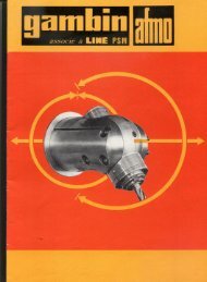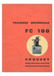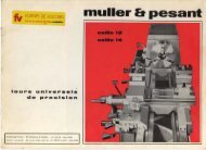
TURRET MILLING MACHINES - Usinages
TURRET MILLING MACHINES - Usinages
TURRET MILLING MACHINES - Usinages

Create successful ePaper yourself
Turn your PDF publications into a flip-book with our unique Google optimized e-Paper software.
KNEEPage 11The knee has travel limitations by means of two screws N0.-588 located on the column andknee, and a positioning brake operated by means of the handle No-562 located on the front.TABLEThe table travels can be limited by means of the-fixed stop No.-3089 screwed to the crosscarriage and two sliding stops in the T-groove located in the front thereof, which are fastenedin position by means of the nut No-358For braking in positioning, operate the hinged handle No.-571.CROSS SADDLEThe cross saddle carries at its right side a centralized greasing pump No 586, which providesoil for the longitudinal motion of table and cross motion of carriage. Also, it carries out thelubrication of the longitudinal and cross spindle. It has a locking brake No.571.IMPORTANT.- When working without using the table, knee or cross motions, be sure thatthese are braked.SETTING THE SADDLESAll sliding parts of the saddles carry lengthwise a setting tapered guideway, which can beoperated by means of the grooved head screw No-561, under the same denomination on thethree setting tapered guideways.OPERATIONTighten slowly the screw No.561 effecting the turning of the corresponding handle until aslight resistance in the handle turning will be noticed.CLEARANCE SETTING ON THE SPINDLEOn the dual supported nut holder No.-3085 for the longitudinal No. 594 and No.580 cross feedspindles, in the nut housings, there are fitted two nuts each separate one from other in orderto eliminate all clearances produced at the long run.To shorten this distance, use the screws No-579 and also the other crews No.578, promotingthe locking of No.-579. To remove the spindle clearances, proceed as follows.TABLELoosen and remove the left side of table No.3092 and move the latter by means of the handleNQ-3096 on the right side until being able to remove with a screw driver the stop screwsNo.578 and eliminate the clearance with the screw No.579, until obtaining a smooth andprecise turning.