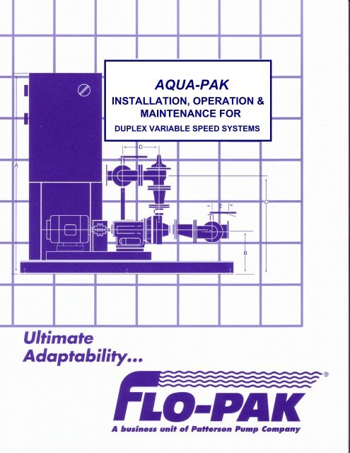
Duplex Variable Speed Systems - Patterson Pump Company
Duplex Variable Speed Systems - Patterson Pump Company
Duplex Variable Speed Systems - Patterson Pump Company
- No tags were found...

Create successful ePaper yourself
Turn your PDF publications into a flip-book with our unique Google optimized e-Paper software.
TABLE OF CONTENTSSECTION 1MECHANICAL & ELECTRICAL DATA Installation and Storage Requirements System Installation, Operation & Maintenance Manual Maintenance Schedule for Packaged <strong>Pump</strong> <strong>Systems</strong> Sequence of Operation Electrical Schematics <strong>Duplex</strong> Amperage ChartSECTION 2PUMP Assembly Section for DAP 1 series, B05-83429 Assembly Section for DAP 2 series, B05-82811 Assembly Section for DAP 3 series, A05-83474 Assembly Section for DAP 4 series, B05-83431
INSTALLATION AND STORAGE REQUIREMENTS FORPUMP SKID UNITINSTALLATION:1. The skid mounting surface can be a pad, but preferably a footing to support the entireperimeter of each of the skid unit(s). This footing should be designed in accordance withlocal building codes for the support of similar steel structures.2. Typically the skid will be fabricated WITHOUT anchor bolt holes. Anchoring of the skid isdone by placing anchor bolt plates over the bottom of the skid framing member andsecuring to the footing with expansion or epoxy anchor bolts. The skid is leveled, pipingand electrical installation are complete before anchoring. For most installations, a total ofeight (8) such anchors are recommended (local authorities may dictate otherwise) foreach unit. This would include two (2) anchors down each long side (evenly spaced), withone (2) at each end (evenly spaced). For suggested anchor detail, see sketch attached.3. After the skid is installed and leveled, but before anchoring, check the doors for fit andease of movement. The entire package is assembled on a level surface at the factoryand checked for proper operation before shipment. Occasionally, when the building isset, the doors do not line- up as they should. This can usually be corrected by shimmingto level the skid on the foundation. Some experimenting may be required as each footingwill vary slightly and the shim may need to be shifted until satisfactory door alignment isachieved. Once proper alignment is achieved the skid should be anchored down and theinterior of the skid filled with concrete over a packed granular fill (gravel). The concreteshould be 4"-6" thick and finished with some surface texture. For deckplated skids, theperimeter members of the skid should be grouted.4. For skids with poured concrete floors, once the floor has cured the baseplate is to begrouted with a non-shrink grout.5. The field electrician will need to connect the building heater. The field electrician isresponsible for grounding the building per local codes.6. All bolts need to be tightened after shipment. Bolts can become loose due to vibrationfrom traveling and loading and unloading.7. All valves are to be in the closed position prior to filling the system.8. All drains in system that are to be field connected need to be routed appropriately by theinstalling contractor.9. It is the installing contractor’s responsibility to inspect the entire package before receivingthe unit. Any damage must be noted in writing on the bill of lading. Pictures should betaken when possible. Failure to do so could result in a denial of a warranty claim.10. All flexible coupled pumps shall be field aligned once the building has been anchored.<strong>Pump</strong>s are factory aligned, but vibrations in shipping and flexing of the station duringloading and unloading may change the alignment. This shall be done by the installingcontractor.
STORAGE:1. Place on a dry, hard, level surface.2. Protect from weather and airborne contamination (if not enclosed).3. Protect from effects of temperature extremes and humidity, to prevent condensation.4. Protect from physical damage.5. Maintain corrosion protection on exposed bare metal surfaces.6. Rotate pump shaft by hand at least once per week. Rotate two revolutions stopping at apoint 90 degrees from the initial shaft position.
SKID UNLOADING GUIDELIFT ARM POSITIONING: The skid lifting arms consist of two pipes inserted through two larger Sch 40pipes that are an integral part of the skid structure. The smaller pipes areapproximately 4 FT longer than the skid width and when properly positionedwill expand beyond the skid on each side. It is recommended that the liftercables not be located farther than 6" form the skid structure. On larger units, the lifting arms are welded in place and are approximately 8inches wider than the skid width, 4 inches on each side. On small units, four 5/8” eyebolts are used instead of lifting arms.RIGGING: The lower cables attach between the four lift points on the skid and thespreader bar (see sketch). The cables (supplied by the crane operator)should be long enough so that the angle between the cables does not exceedthe recommendation of the cable supplier. We have found that an includedangle of 40-45 degrees between cables allows for good stability. The longerthe cables, the more stable the load. The spreader bar (supplied by the crane operator), should be about two feetwider than the skid base. The upper cables should be somewhat longer thanthe lower cables (approximately 20%). Again, the cable manufacturer'srecommendation should be followed. Proper rigging of the skid for lifting is the responsibility of the customer. Theabove rigging suggestions are meant only as a guide and are not to beconstrued as complete instructions, consequently <strong>Patterson</strong> <strong>Pump</strong> <strong>Company</strong>shall not be responsible for the use or misuse of these suggestions. Thecustomer is encouraged to retain the services of a qualified contractorexperienced in the rigging of similar structures.
P.O. BOX 790Toccoa, Georgia 30577Telephone: 706-886-2101Fax: 706-886-0023www.flo-pak.comINSTALLATION, OPERATION & MAINTENANCE MANUALRead this entire manual before proceeding.SECTION I – INTRODUCTION1-1 This manual provides general instructions for the installation andmaintenance of the package pumping unit manufactured by Flo-Pak, Inc. /A Business Unit of <strong>Patterson</strong> <strong>Pump</strong> <strong>Company</strong>, Toccoa, Georgia.1-2 After carefully uncrating or unpacking, check the equipment against theshipping papers, and inspect for any damage incurred during shipment.Immediately notify the carrier of any damage or shortage found.1-3 The type and sizing of the unit was built to meet requirements provided bythe purchaser. Among the more important requirements are the following: Liquid pumped Flow in gallons-per-minute Temperature of liquid pumped degree Fahrenheit Suction condition, pressure or lift Discharge pressure Power supply characteristics Location1-4 If any of the requirements change after the order was placed, we suggestthat each change be reviewed with the factory.CAUTION: Operation of the package under conditions different from thedesign requirements may void the warranty!SECTION II – INSTALLATION1
2-1 LocationSelect a location for the package which will be clean, well ventilated,properly drained, and provide accessibility for inspection andmaintenance. Outdoor installation may require protection from theelements, particularly freezing.PACKAGE PUMPING SYSTEMS*** Installation*** Operation*** MaintenanceRead the entire manual before attempting to install, operate or repair thisequipment.Properly installed your Flo-Pak package will give you satisfactory anddependable service. We urge that you carefully read these step-by-stepinstructions to simplify any problems of installation, operation or repair.Failure to read and comply with installation and operation instruction willvoid the responsibility of the manufacturer and may also result in bodilyinjury, as well as property damage.This manual is intended to be a permanent part of your packageinstallation and should be preserved in a convenient location for readyreference. If these instructions should be come soiled, obtain a new copyfrom Flo-Pak. Be sure to include the package serial number you request.2-2 FoundationConcrete (reinforcement as necessary or required) is most widely used forthe foundation. In sufficient mass it provides rigid support whichminimizes deflection and vibration. It may be located on soil, structuralsteel or building floors, provided the combined weight of the package,grout and foundation does not exceed the allowable bearing load of thesupport. Allowable bearing loads of structural steel and floors can beobtained form engineering handbooks, building codes or localcommunities which give the recommended allowable bearing loads fordifferent types of soil.2-3 Before pouring, roughen the top surface to provide a good bond.Ordinarily the proportions used are 1 part cement to 3 parts sand and 4parts medium aggregate.2
2-4 If vibration or noise will be objectionable, as in office building, it may beadvisable to use vibration dampeners between the package unit andfoundation in conjunction with suction and discharge piping vibrationsuppressor.2-5 MountingSet the package unit on the foundation base. Level the unit and check thealignment on the bearing frame units; tighten the foundation bolts.2-6 Alignment Bearing Frame Units OnlyReliable, trouble-free and efficient operation of the unit depends on thecorrect alignment of the pumps and driver shafts. Misalignment may bethe cause of:a. Noisy pump operationb. Vibrationc. Premature bearing failured. Excessive coupling wearNote: Complete units are aligned at the factory. Experience has shownthat all bases, no matter how rugged or deep in section, will twistduring shipment. At the very least, the alignment must be checkedafter mounting.Factors which may change the alignment of the unit after the initialinstallation:a. Settling of the foundationb. Springing of the basec. Piping straind. Settling of the buildinge. Shift of pump driver on the foundation2-7 GroutingGrouting compensates for unevenness in the foundation and the base, aswell as distributes the weight of the unit uniformly over the foundation. Italso helps to prevent the unit from shifting after mounting. It is essentialthat the unit be expertly grouted by use of non-shrinking grout. Grout theunit as follows:a. Build a form of plywood or thin planking around the foundation tocontain the grout. Support adequately to prevent deformation.3
2-8 Pipingb. Soak the top of the concrete pad thoroughly with water beforegrouting. Remove all surface water before pouring.c. A recommended mix of grout satisfactory for most applications is asfollows:1. One part of normal Portland Cement – 94#2. One part of Embeco Cement – 100#3. One part of coarse clean sand – 100#4. One and one-half parts of ¼” pea gravel (1½ cu. Ft.)5. approximately 5 ½ gallons waterd. Pour the grout into the base and, while pouring, tamp liberally inorder to fill cavities and prevent air pockets. In order to prevent thebase from shifting, grout 4” out from all sides of the base. Slantoutside edges of the grout to prevent chipping.e. Approximately fourteen days after the grout has been poured orwhen the grout is thoroughly dried, apply an oil base paint to allexposed surfaces of the grout to prevent air and moisture fromcoming in contact with the grout.The suction and discharge piping should be arranged for the mostsimple, direct layout and be of sufficient size and internally free offoreign material. The piping must never be pulled into position by theflange bolts. It must be be independently supported and arranged inorder to not induce any strain on the package.Note:Piping should be cleaned and flushed prior to installing thepackage. A large number of packing, mechanical seals andseizure troubles of the pumps are due to improperly cleanedsystem.2-9 ElectricityConnect the power supply to the package conforming to the NationalElectrical and local codes. Line voltage and wire capacity must matchthe rating stamped on the control panel nameplate.a. Only when the coupling halves are disconnected (framemounted pumps) and the water supply is to the suction of thepumps, momentarily energize the panel and check that rotationof the pumps is correct by setting the hand-off-auto switch intothe hand position.4
. If the rotation is inaccurate, correct by changing any two of thethree power leads.SECTION III – LUBRICATION3-1 CouplingsCouplings with rubber drive parts do not require lubrication; however, mostcouplings do require some form of lubrication. After completion ofinstallation and alignment, and before operating the unit, lubricatecouplings in accordance with the manufacturer’s specific instructioncontained in the package installation manual.3-2 Ball BearingsReasonable care and proper lubrication of bearings will result in manyyears of service. The lubricant provides a film between the balls,separator and races, giving low friction and preventing excessivetemperature rise and corrosion.3-3 The normal life of ball bearings is terminated only by fatigue. Improperlubrication practices are the primary cause of failure. Good practiceincludes the following:a. Keep lubricant clean; provide and use a dust-tight cover on thestorage container.b. Use the oldest lubricant first.c. Clean lubrication fittings before re-lubrication.d. Use clean dispensing equipment.e. Use the proper amount of lubricant. Too much grease results inchurning and unnecessary power consumption, rapid heating tohigh temperatures which break down the grease.f. Use the correct lubricant. Grease Lithium Soap Base, meetingNational Lubricating Grease Institute Grade 2 specifications. Thishas a safe operating temperature higher than 300 degreesFahrenheit.5
3-4 Operating TemperatureUse of the lubricants and procedures given in this manual will allow safeoperation at bearing temperatures to 250 degrees Fahrenheit. Pastexperience, however, indicates the normal temperature will not exceed250 degrees if the pumped fluid is well below that temperature.3-5 A high normal operating temperature is not a sign of bearing failure.Normal temperatures vary with the seasons and the environment and mayrange from 0 to approximately 200 degrees Fahrenheit. A continuous risefrom established normal operating temperature indicates trouble andprobable failure of the bearings. Shut down the unit immediately.Disassemble, clean and inspect the bearings. Replace if required.3-6 Re-LubricationGrease that has been in service does not “wear away.” It needs replacingonly because of contamination by dust, metal particles, moisture or hightemperature breakdown.a. Thoroughly clean greased fitting.b. Remove grease drain plug on equipment so equipped.c. Inject clean new grease.SECTION IV – OPERATION4-1 When making an initial start, after installation or major maintenance, checkthe following:a. Coupling alignment (if frame mounted).b. Bearing lubricant on pumps and drives.4-2 Start the package as follows:1. When possible, turn the pump shaft by hand to make sure parts donot bind.2. Open suction valves.3. Start drive in “hand” and check rotation. (Correct as necessary.)4. With pump running in “hand” regulate system pressure by adjustingthe pressure regulating valve. (See data sheet in manual.) Repeatthis for all pumps on package.6
SECTION V – MAINTENANCEWARNING – DISCONNECT THE POWER TO ANY ROTATING ORELECTRICAL COMPONENTS BEFORE STARTING ANYREPAIRS!5-1 Regular consistent maintenance is the best way to avoid serious troublewhich may require taking the unit out of service for extensive repair.5-2 BearingsIt is essential to provide proper lubrication and keep bearings clean.Frequency of lubrication must be determined by experience as it dependsupon bearing size, speed, operating conditions and location(environment). Table 1 should be used as a guide for grease relubrication.TABLE 1Operating ConditionsNormal, 8-hour day operation.Area free of dust and damaging atmosphere.Severe, 24-hour day operation.Area with moderate dust and/or damaging atmosphere oroutdoor service.Light, approximately 10-hour week.Area relatively free of dust and damaging atmosphere.LubricateEvery six (6)months.Every month.Every year.5-3 Alignment – (Bearing frame unit only) – Check alignment yearly.7
TABLE 2Problems Probable Cause RemedyFailure to deliverliquid or sufficientpressure.Overload of driver.Vibration or noise.All pumps runninglag units cycle offand back on again.Control valve notadjusted correctly.Incorrect pump rotation.Discharge head toohigh.Impeller passagesrestricted.<strong>Pump</strong> not up to speed.Worn wearing rings.Damaged impeller.Total head lower thanratingMechanical problem inpump or driver.Misalignment bearing(frame units only).Worn ball bearing.Cracked foundation.Control valve settingand start pressureswitch not adjustedcorrectly in relation toone another.Too low setting on startdelay timer.Adjust control valve. (See valvemanual.)Change rotation.Check that all discharge valves are openand discharge line is free formobstructions. In some cases theinstallation needs to be altered or pumpof suitable rating supplied.Disassemble the pump and clean theimpeller.Check for low motor voltage or motoroverload.Replace worn parts.Replace or repair impeller.Check suction and discharge pressureand determine the total dynamic head.If TDH is lower than rated, throttledischarge valve to rated TDH.See if unit turns freely.Realign unit.Replace bearings.Replace foundation.Readjust.Readjust.8
All pumps runninglag units cycle offand back on again.TABLE 2(Continued)Package undersized for Verify operating flow and head.load.Low suction alarmtripping.All other alarms.Low suction switchadjusted incorrectly orpoorly.Actual low suctioncondition.Switches adjustedincorrectly.Actual alarm condition.Delay timer set too low.Check adjustment.Check suction pressure with test gauge.Readjust.Verify and correct.Increase time delay.5-4 Spare PartsTo keep delay to a minimum when package repairs are required, wesuggest that the following spare parts be stocked:Panela. Spare set of fuses.b. Spare timer.c. Spare relay.d. Spare system pressure switch and suction pressure switch.<strong>Pump</strong>sa. Spare mechanical seal for each size pump.b. Spare casing gasket for each size pump.c. Spare shaft sleeve for each size pump.d. Spare impeller for each size pump.5-5 To obtain quick and accurate service when ordering spare parts, providethe following information:1. Package serial number.2. The name and number of parts shown on the data provided for theindividual component.3. Quantity required on each item.9
Aid may be obtained from the Flo-Pak representative in your area or from thefactory.Flo-Pak, Inc.P.O. Box 790Toccoa, Georgia 30577Telephone: 706-886-2101www.flo-pak.comA Business Unit of <strong>Patterson</strong> <strong>Pump</strong> <strong>Company</strong>5/28/0410
PUMP COMPANY / A Subsidiary of The Gorman Rupp Co.P.O. Box 790 / Toccoa, Georgia 30577 / (706) 886-2101 / FAX (706) 886-0023www.pattersonpumps.comGeneral <strong>Pump</strong> Inspection and Maintenance SchedulePackaged <strong>Pump</strong> <strong>Systems</strong>Any additional inspections, maintenance, or tests required by NFPA- Standards for fire pumps are excluded.Refer to NFPA Standards for additional requirements for fire pumps.Actions required only for specific pump types are so noted.The symbol ( ) used in the table below indicates that the action indicated may not be applicable to a specific pump of a particular type.For more information regarding inspection and maintenance requirements refer to the <strong>Patterson</strong> O & M manual supplied with the pump.Contact <strong>Patterson</strong> <strong>Pump</strong> <strong>Company</strong> if assistance is needed to determine the inspection and service requirements for a specific pump.Inspect ( ) or service ( ) at the indicated calendar time or run timeinterval whichever comes first 4 hours Routinely MonthlyReplenish grease lubricated sleeve bearing grease per the O & Mmanual using the manual grease lubricator. Perform every 3 monthswhile idle. (vertical wet pit pumps so equipped)Unusual noiseUnusual vibrationUnusual temperatureLeaks in pump or pipingPressure gauge readingsVisual inspection of equipment general conditionAnytime a pump is opened, inspect the running clearances and restorethem to original specifications if the running clearances have doubled(adjust ring clearances if so supplied or install new wear rings)Anytime a pump is opened, inspect the impeller for corrosion orexcessive wear.Packing box verify slight leakage (if excessive, adjust gland or sealwater valve; replace packing if required)Mechanical seal (should be no leakage)Drain lines are working properlyCoupling integrityDrive shaft integrityVerify proper operation of oil drip lubricator (vertical wet pit pumps soequipped)Verify proper operation of automatic grease lubricator (vertical wet pitpumps so equipped)Operate the pump(note for vertical wet pit pumps first verify proper lubrication )Tightness of foundation and hold-down boltsCheck coupling alignment and integrity (maintain records)Add grease to pump anti-friction bearings (maintain records)Add grease to universal joint shafting u-joint bearings, anti-frictionsteady bearings (maintain records)Add grease to coupling (maintain records)Change anti-friction bearing oil (maintain records)Replace packing (all packing; not just the outermost ring)Clean and oil gland bolts (packed pumps)Verify free movement of packing glands (packed pumps)Universal joint shafting and steady bearings wear check (replacebearings if required)Clean packing boxCheck and flush seal water and drain pipingPerform a comparative field test (flow, pressures, and power) withcalibrated instruments. Restore internal running clearances if results areunsatisfactory (install new wear rings).Perform a comparative vibration testRemove packing and inspect sleeve(s). Replace if worn. (packedpumps)Realign coupled pumps (maintain records)Remove pump handhole covers and inspect impeller for corrosion andexcessive wear (sewage pumps)Remove handhole covers to inspect the wear ring clearances. When thewear ring clearances have doubled, adjust the ring clearances to originalspecifications if so supplied or install new wear rings (sewage pumps).2000 hours or 3months4000 hours or 6months8000 hours or12 monthsExamine running clearance between propeller and propeller housing.When the running clearance has doubled, repair or replace the housing,housing liner, or propeller as appropriate. (model AFV axial flowpumps)Inspect the impeller running clearance. Inspect the impeller housing forexcessive wear. If the wear is not excessive, perform impelleradjustment. If the wear is excessive, repair or replace the impellerhousing. (open impeller mixed flow pumps, such as models SAF,SAFV, SAFH, or TMF)Inspect batteries & battery charger for proper charge.Observe operation of fans & dampers such that the fans & dampersoperate at set temperature, and damper opens upon operation of thediesel engine.Jockey <strong>Pump</strong> See manual for specific jockey maintenancerequirements.Engine Maintenance (Belts / Filters / Oil / Fuel Strainer) [See O&Mmanual for Engine]Replace any worn caulk around pipe exits on buildings.Building Heater - Inspect for proper operation.Inspect operation of all valves in system.Lights (Outside, Inside, Emergency) Inspect for proper operation.Issue 020907
Sequence of Operation<strong>Duplex</strong> <strong>Variable</strong> <strong>Speed</strong> BoosterRev. 2 07/19/10(For PLC program Rev 8 and later)Basic OperationThe pumps are started and stopped according to discharge pressure.The “PID Set-point” is the set-point pressure desired to be maintained at the discharge header.The start and stop set-points for the lead and lag pumps are “deviations” below the “PID Set-point”.The operator can adjust the speed of the VFDs manually by placing the speed command to manual in the operator interfaceand altering the pump(s) speed by using the increase and decrease (up and down arrow) buttons.The lead pump will start after an adjustable time delay when the discharge pressure drops to the start lead pressure set-point.The lag pump will start after an adjustable time delay when the discharge pressure drops to the start lag pump pressureset-point or if the optional flow sensor is supplied, when the flow rate meets or exceeds the start lag pump set-point.Once a pump has started, it will run for an adjustable minimum run time. The factory default minimum run time is set to 10minutes.Shutdown will occur in reverse order according to the starting sequence.The lag pump will stop when the discharge pressure has risen to the stop lag pump set-point, its minimum run timer hasexpired and if the optional flow sensor is supplied, when the flow rate drops to or below the stop lag pump set-point.The lead pump will stop when the discharge pressure has risen to the stop lead pump set-point, its minimum run timer hasexpired, the lag pump has stopped, the speed (PID Output) has dropped below an adjustable set-point and there is no flowas sensed by the optional no flow switch.An optional no-flow switch can be provided to hold the lead pump on as long as there is 5 or more GPM still flowing throughthe system. This prevents unnecessary “cycling” of the lead pump.Equal sized pumps are alternated every time all equal pumps have stopped (duty cycle alternation) or every 24 hours,whichever occurs first. The operator can select the hour for the 24 hour alternation.Once the system piping has been filled and pressurized, the operator simply performs the following:Set the HOA switches in the automatic position.Set the desired PID pressure setpoint.Set the starting and stopping set-point pressure deviations of the lead and lag pumps.Set the starting and stopping flow rate set-points of the lag pumps if optional flow sensing is provided.Set the speed control mode to “Auto”System Safety Startup ModeIn the automatic mode of operation, if the pumps are stopped for certain conditions such as a shutdown alarm or if the systemis disabled, the controller contains a routine which will take the system into a safety startup mode once the shutdown alarmcondition has been reset or the system has been re-enabled.Once a shutdown condition has been reset or the system has been re-enabled, the controller compares the current dischargepressure to the goal (final) PID set-point pressure. If the current discharge pressure is not more than 5 PSI below the goal PID1
set-point, then the goal set-point is moved into the set-point register and normal operation is resumed. If the current dischargepressure is more than 5 PSI below the goal PID set-point, then the current discharge pressure plus the lead start deviation(typically set at 1 psi) is used as the initial startup set-point.When the discharge pressure reaches the initial set-point, then 5 psi is added to the set-point after a 10 second time delay.This routine continues until the discharge pressure is within 5 psi of the goal set-point.Once the discharge pressure is within 5 psi of the goal set-point, the goal set-point is moved into the set-point register andnormal operation is resumed.During the startup mode, the lag pumps are locked out from starting (in the automatic mode of operation).During the startup mode, if the system fails to maintain any set-point pressure for an adjustable time (default of 5 minutes), thepump is stopped and the system is locked out, requiring a manual reset.The conditions are as follows:- Power loss- Low suction shutdown- High suction shutdown (if option provided)- High discharge shutdown- Irregular power (if option provided)- Discharge pressure transducer failure- All pumps have failed- All pump HOA switches are turned off- System has been disabled (via timeclock enable/disable)- Goal set-point has been set to “0”Low Suction ShutdownIn the event of low suction (supply) pressure, the pumps will be stopped and the Low Suction Pressure alarm will be initiatedafter an adjustable time delay. The alarm will automatically reset after 10 seconds if configured for auto reset or will requirea manual reset if the alarm is configured for manual reset when the pressure rises above the alarm set-point. Once reset, thepumps will be re-enabled.High Suction ShutdownIn the event of the optional high suction (supply) pressure, the pumps will be stopped and the High Suction Pressure alarmwill be initiated after an adjustable time delay. The alarm will automatically reset after 10 seconds if configured for auto resetor will require a manual reset if the alarm is configured for manual reset when the pressure drops below the alarm set-point.Once reset, the pumps will be re-enabled.Low Discharge AlarmIn the event of a low discharge pressure condition, the Low Discharge Pressure alarm will be initiated after an adjustable timedelay. The alarm will automatically reset after 10 seconds if configured for auto reset or will require a manual reset if the alarmis configured for manual reset when the discharge pressure rises above the alarm set-point.High Discharge ShutdownIn the event of a high discharge pressure condition, the pumps will be stopped and the High Discharge Pressure alarm will beinitiated after an adjustable time delay. The alarm will automatically reset after 10 seconds if configured for auto reset or willrequire a manual reset if the alarm is configured for manual reset when the discharge pressure drops below the alarmset-point. Once the alarm is reset, the pumps will be re-enabled.Discharge Pressure Transducer FailureIn the event of discharge pressure transducer failure, the pumps will be stopped and the PLC will remove this failed sensorfrom operation. The operator will be required to start the pumps manually (Hand) and use the manual speed mode for speedadjustment.PLC FailureIn the event of programmable logic controller (PLC) failure, the pumps will stop. The operator will be able to start the pumpsmanually in an emergency only using the Remote/Local key on each VFD. When the pumps are started in this manner, there2
are no pump or system shutdown safeties. The operator must monitor the system continuously when operating pumps in thebackup start mode to prevent damage to the system, the pumps or other devices connected to the system.HMI (Operator Interface) FailureIn the event that the HMI should fail, the PLC will continue to operate the system based on the last states for which the PLCwas adjusted via the HMI. For example, if the HOA switches and speed control mode were left in the “auto” position, the PLCwill continue to start, stop and regulate the pumps speed as if the HMI had never failed. Should the operator be required tostop the pumps, each VFD can be stopped at the VFD keypad by pressing the “Stop” key, the individual pump branch breakerscan be opened or the main power disconnect can be opened to de-energize the system. Once power is restored, the systemwill return to the operating state before power was removed (will operate pumps automatically).<strong>Pump</strong>/VFD FailureIn the event of a VFD fault or if the pump(s) HOA switch is placed in the off position, the PLC will ignore the failed pump in thestarting/running sequence and will start the remaining pump in its place. The PLC will put the failed pump back into thestarting/running sequence once the VFD fault has been cleared or when the HOA switch is put into the Auto position.Operator InterfaceAll start/stop set-points and timers are adjustable via the operator interface. The touchscreen is menu driven for ease ofnavigation.“System Setup” requires a level 1 password. These are the set-point screens for items such as PID set-point pressure, pumpsstart/stop, low suction or low discharge alarms, pump(s) minimum run timers, etc. To change data, the operator touches thedata to be changed and a keypad will pop up. The operator inputs the new data and presses the enter (ENT) key. Note that ifthe “defaults loaded” alarm condition exists, the operator will not be able to change any set-points. The “defaults loaded” alarmmust first be cleared in order to be able to change set-points.“Alarms” displays the alarm screen. The operator can touch an alarm lamp to bring up the reset type screen. If the operatordesires a particular alarm to be of the manual reset type, the “Configuration” button is pressed to enter the reset typeconfiguration screen. Not all alarm resets are configurable.Alarms that require a manual reset are reset via the “Manual Alarms Reset” button located on the alarms screen.While in the “Alarms” screens, pressing the “Last 20 Alarms” button displays the last 20 alarms in order of occurrence. Theoperator uses the scroll up and scroll down arrows to scroll the list. The alarm status is such that if the alarm is red in color, itstill exists or if white in color has been reset.CommunicationThe control panel provides one dry normally open contact for system common alarm.3
MAIN SCREENPUMPS SPEEDPUMP 2 HOA SWITCHSET-POINT DISPLAYSTARTUP MODE LAMPDISCHARGE PRESSUREFLOW SWITCH LAMPPUMPS E-STOPTURNS OFF ALL HOASWITCHES AT ONCESYSTEM ENABLED /DISABLED LAMPMAIN MENUALARM SILENCEPUMP 1 FAILURE INDICATORPUMP 1 RUNNING INDICATORSEQUENCE POSITION LAMPS
MAIN MENU
SYSTEM DATAPUMPS SPEEDSET-POINT DISPLAYSTARTUP MODE LAMPDISCHARGE PRESSUREFLOW SWITCH LAMPPUMPS E-STOPTURNS OFF ALL HOASWITCHES AT ONCESYSTEM ENABLED /DISABLED LAMPMAIN MENUALARM SILENCESEQUENCE POSITION LAMPS
TREND DATA
SPEED CONTROL SCREEN
LARGE PRESSURE DISPLAY
ELAPSED TIMERS
DATE / TIME
ALARM SCREENSTOUCH ALARM TO VIEW RESET TYPETOUCH FOR LAST 20 ALARMS SCREENPUMPS START LOGIC SCREENSRESET FOR MANUAL RESET TYPE ALARMS
ALARM RESET TYPE SCREENTOUCH FOR ALARM RESET TYPECONFIGURATION SCREEN
ALARM RESET TYPE CONFIGURATION SCREENTOUCH FOR AUTO RESETTOUCH FOR MANUAL RESETVIEW SELECTED RESET TYPE
LAST 20 ALARMS SCREEN
PUMPS START LOGIC SCREENS
PUMPS START LOGIC SCREENS
PUMPS START LOGIC SCREENS
SETUP SCREEN
SETUP SCREENTOUCH DATA TO CHANGE VALUE
SETUP SCREEN
SETUP SCREEN
SETUP SCREEN
SETUP SCREEN
SETUP SCREEN
SETUP SCREEN
SETUP SCREEN
SETUP SCREEN
SETUP SCREEN
SETUP SCREEN
12OVERCURRENT PROTECTIONPROVIDED AND INSTALLEDIN ACCORDANCE WITH NFPA70(NEC) BY OTHERSTHROUGH-DOOROPERATORVFDs EXTERNAL TO PANEL345678POWER FEEDXXXV/3PH/60HZGROUNDDSMPDBL1L2L3L1L2L3CB11L11L21L3U1V1W1PUMP 1VFDABB ACH550U2V2W2<strong>Pump</strong> #1Motor91 01 11/2 AmpF3L1L2L3CB22L12L22L3U1V1W1PUMP 2VFDU2V2W2<strong>Pump</strong> #2Motor1 2ABB ACH5501 35L15L25L3L1L2L31 41 51 61 71 8L1 PML2PhaseMonitorL3SURGEARRESTOR1 92 0OPTIONALOPTIONAL2 12 22 3FAMP2 42 52 6L1L22 72 82 93 0CONTROL TRANSFORMERVA17 16 NFAMP3 13 23 33 43 53 63 73 83 94 04 1VFDs EXTERNAL TO PANELDAP-X-25 208 VoltDAP-X-25 230 VoltDAP-X-20 208 VoltDAP-X-20 230 Volt4 24 34 44 54 64 717 NDUPLEX VARIABLE SPEED AQUA~FLOPACPage 1AT MPUMP #1 PUMP #2Power FeedI NC.A business unit of <strong>Patterson</strong> <strong>Pump</strong> <strong>Company</strong>HPFLABRKRHP.FA LBRKRXXXV/3PH/60HzMCA - XXDrawn By: WRW Date 07/19/2010Dwg Number: A85-109239-1 Rev: 1
17 N4849505117 RED15 BLUELOW SUCTION PRESSURE OR LEVEL SWITCH15 11 BLUELIC200UAL006INPUTI 1100-240VACNGNDOUTPUTQ1C1NN52VC535415 BLUENO FLOWFLOW SWITCH15 22 BLUEI 25556OPTIONALQ257Q35859606115 BLUERUNNING15 1921 3FAULT2224 43 BLUE4 BLUEI 3I 4Q4Q5C245 YEL45COMMON ALARM46 YEL 24VDC/240VAC 2 AMPS4662PUMP 1 VFD636465666715 BLUERUNNING15 1921 5FAULT2224 65 BLUE6 BLUEI 5I 6VFDs EXTERNAL TO PANEL68PUMP 2 VFDQ62626 BLUE10146970C33333 BLUEPUMP 1VFD13 11 1271727374I 7I 8Q7C4273427 BLUE34 BLUE1014PUMP 2VFD13 11 127576Q87778I 9C579808115 BLUEOPTIONALCNOPM-1PHASE MONITOR10 BLUEI 1082838415 BLUEOPTIONALHIGH SUCTION PRESSURE SWITCH151111 BLUEI 1185I 1286I 13Q929 REDNALARM WHISTLE8714 BLUECOM1Q1 0888914 BLUE14 BLUECOM2COM3C617 RED90VDC14 BLUE9115 BLUE421592939417 RED 17 RED17NDUPLEX VARIABLE SPEED AQUA~FLOPACPage 1BT MI NC.A business unit of <strong>Patterson</strong> <strong>Pump</strong> <strong>Company</strong>Drawn By: WRW Date07/19/2010Dwg Number:A85-109239-1 Rev: 1
17N959697989917L 1L 224VDCPOWERSUPPLYPS1NN1001011025051G103104105106505151IN1-107108109110111112113114DISCHARGE PRESSURE TRANSDUCER4-20ma = 0-300 PSIG+-DATA INDUSTRIALMODEL 220B FLOW SENSORMOUNTED AND WIRED BY OTHERS5052GIN1+IN1JPIN2-I COMI OUTVOUTVCOMVFDs EXTERNAL TO PANEL62622 +PUMP 1 VFD6363G3 -115116117SLDBLKREDSLD+ -SIGNALLOOPMODEL310+-5053GIN2+IN2JP6263626323+PUMP 2 VFD-118119FLOW RATE TRANSDUCERMOUNTED AND WIRED BY OTHERSWITHIN 5 FEET OF FLOW SENSORG120OPTIONAL121122123124125126127128PORT 1RS232PORT 2RS485129OPERATOR INTERFACE13013113213313451 501355113650137138139140141INSTALLED OPTIONSPHASE MONITORSURGE ARRESTORFLOW SENSOR/TRANSMITTERNO FLOW SWITCHHIGH SUCTION PRESSURE SWITCHLARGE OPERATOR INTERFACEDUPLEX VARIABLE SPEED AQUA~FLOPACPage 1CT MI NC.A business unit of <strong>Patterson</strong> <strong>Pump</strong> <strong>Company</strong>Drawn By: WRW Date07/19/2010Dwg Number:A85-109239-1 Rev: 1
12OVERCURRENT PROTECTIONPROVIDED AND INSTALLEDIN ACCORDANCE WITH NFPA70(NEC) BY OTHERSTHROUGH-DOOROPERATORVFDs INSIDE PANEL345678POWER FEEDXXXV/3PH/60HZGROUNDDSMPDBL1L2L3L1L2L3CB11L11L21L3U1V1W1PUMP 1VFDABB ACS310U2V2W2<strong>Pump</strong> #1Motor91 01 11/2 AmpF3L1L2L3CB22L12L22L3U1V1W1PUMP 2VFDU2V2W2<strong>Pump</strong> #2Motor1 2ABB ACS3101 35L15L25L3L1L2L31 41 51 61 71 8L1 PML2PhaseMonitorL3SURGEARRESTOR1 92 0OPTIONALOPTIONAL2 12 22 3F1X AMP2 42 52 64L14L22 72 82 93 0CONTROL TRANSFORMER300VA17 16 NF23-1/2 AMP3 13 23 3T-STAT17 17N17 18 NENCLOSURE COOLING FAN3 43 53 63 73 83 94 04 14 24 34 44 54 64 7VFDs INSIDE PANELDAP-X-25 480 VoltDAP-X-15 230 VoltDAP-X-15 208 VoltDAP-X-20 480 VoltDAP-X-10 230 VoltDAP-X-10 208 VoltDAP-X-15 480 VoltDAP-X-7 230 VoltDAP-X-7 208 VoltDAP-X-10 480 VoltDAP-X-7 480 VoltDAP-X-5 230 VoltDAP-X-5 208 VoltDAP-X-3 230 VoltDAP-X-3 208 VoltDAP-X-5 480 VoltDAP-X-3 480 VoltDAP-X-2 480 VoltDAP-X-2 230 VoltDAP-X-2 208 Volt17 NDUPLEX VARIABLE SPEED AQUA~FLOPACPage 2AT MPUMP #1 PUMP #2Power FeedI NC.A business unit of <strong>Patterson</strong> <strong>Pump</strong> <strong>Company</strong>HPFLABRKRHP.FA LBRKRXXXV/3PH/60HzMCA - XXDrawn By: WRW Date 07/19/2010Dwg Number: A85-109239-1 Rev: 1
17 N4849505117 RED15 BLUELOW SUCTION PRESSURE OR LEVEL SWITCH15 11 BLUELIC200UAL006INPUTI 1100-240VACNGNDOUTPUTQ1C1NN52VC535415 BLUENO FLOWFLOW SWITCH15 22 BLUEI 25556OPTIONALQ257Q35859606115 BLUERUNNING1719FAULT20213 BLUE4 BLUEI 3I 4Q4Q5C245 YEL45COMMON ALARM46 YEL 24VDC/240VAC 2 AMPS4662PUMP 1 VFD636465666715 BLUERUNNING1719FAULT20215 BLUE6 BLUEI 5I 6VFDs INSIDE PANEL68PUMP 2 VFDQ626 BLUE12PUMP 1VFD6970C333 BLUE9 10 117172I 7Q727 BLUE12PUMP 2VFD7374I 8C434 BLUE910 117576Q87778I 9C579808115 BLUEOPTIONALCNOPM-1PHASE MONITOR10 BLUEI 1082838415 BLUEOPTIONALHIGH SUCTION PRESSURE SWITCH151111 BLUEI 1185I 1286I 13Q929 REDNALARM WHISTLE8714 BLUECOM1Q1 0888914 BLUE14 BLUECOM2COM3C617 RED909115 BLUE14 BLUE152 4 VDC92939417 RED 17 RED17NDUPLEX VARIABLE SPEED AQUA~FLOPACPage 2BT MI NC.A business unit of <strong>Patterson</strong> <strong>Pump</strong> <strong>Company</strong>Drawn By: WRW Date07/19/2010Dwg Number:A85-109239-1 Rev: 1
17N959697989917L 1L 224VDCPOWERSUPPLYPS1NN1001011025051G103104105106505151IN1-107108109110111112113114DISCHARGE PRESSURE TRANSDUCER4-20ma = 0-300 PSIG+-DATA INDUSTRIALMODEL 220B FLOW SENSORMOUNTED AND WIRED BY OTHERS5052GIN1+IN1JPIN2-I COMI OUTVOUTVCOM6263VFDs INSIDE PANEL622 +PUMP 1 VFD63G3 -115116117SLDBLKREDSLD+ -SIGNALLOOPMODEL310+-5053GIN2+IN2JP6263626323+PUMP 2 VFD-118119FLOW RATE TRANSDUCERMOUNTED AND WIRED BY OTHERSWITHIN 5 FEET OF FLOW SENSORG120OPTIONAL121122123124125126127128PORT 1RS232PORT 2RS485129OPERATOR INTERFACE13013113213313451 501355113650137138139140141INSTALLED OPTIONSPHASE MONITORSURGE ARRESTORFLOW SENSOR/TRANSMITTERNO FLOW SWITCHHIGH SUCTION PRESSURE SWITCHLARGE OPERATOR INTERFACEDUPLEX VARIABLE SPEED AQUA~FLOPACPage 2CT MI NC.A business unit of <strong>Patterson</strong> <strong>Pump</strong> <strong>Company</strong>Drawn By: WRW Date07/19/2010Dwg Number:A85-109239-1 Rev: 1
<strong>Duplex</strong> Amperage ChartMODEL208v-3-60hz<strong>Pump</strong>(s) FLA System230v-3-60hz<strong>Pump</strong>(s) FLA System460v-3-60hz<strong>Pump</strong>(s) FLA System380v-3-50hz<strong>Pump</strong>(s) FLA SystemP1 P2 MCA P1 P2 MCA P1 P2 MCAP1 P2 MCADAP-1-2 7.5 7.5 19 6.8 6.8 17 3.4 3.4 9 4.3 4.3 11DAP-1-3 10.6 10.6 26 9.6 9.6 23 4.8 4.8 12 6 6 15DAP-2-3 10.6 10.6 26 9.6 9.6 23 4.8 4.8 12 6 6 15DAP-1-5 16.7 16.7 40 15.2 15.2 36 7.6 7.6 18 9.6 9.6 23DAP-2-5 16.7 16.7 40 15.2 15.2 36 7.6 7.6 18 9.6 9.6 23DAP-2-7 24.2 24.2 56 22 22 51 11 11 26 13.9 13.9 33DAP-3-5 16.7 16.7 40 15.2 15.2 36 7.6 7.6 18 9.6 9.6 23DAP-3-7 24.2 24.2 56 22 22 51 11 11 26 13.9 13.9 33DAP-3-10 30.8 30.8 71 28 28 65 14 14 33 17.7 17.7 41DAP-3-15 46.2 46.2 106 42 42 96 21 21 48 26.5 26.5 61DAP-3-20 59.4 59.4 136 54 54 123 27 27 62 34.1 34.1 78DAP-4-10 30.8 30.8 71 28 28 65 14 14 33 17.7 17.7 41DAP-4-15 46.2 46.2 106 42 42 96 21 21 48 26.5 26.5 61DAP-4-20 59.4 59.4 136 54 54 123 27 27 62 34.1 34.1 78DAP-4-25 74.8 74.8 170 68 68 155 34 34 78 42.9 42.9 98
<strong>Pump</strong> Emergency Backup (Local) Operation<strong>Duplex</strong> <strong>Variable</strong> <strong>Speed</strong> ControllerWith External VFDsCAUTIONTHE BACKUP (LOCAL) VFD STARTING MODE IS FOR EMERGENCY USEONLY IN THE EVENT OF PLC FAILURE.WHILE IN THE BACKUP (LOCAL) VFD STARTING MODE, THERE ARE NOPUMP OR SYSTEM SHUTDOWN SAFTIES.THE SYSTEM MUST BE MONITORED BY THE OPERATOR AT ALL TIMESWHILE OPERATING IN THE BACKUP (LOCAL) VFD STARTING MODE.TO CHANGE VFD TO BACKUP (LOCAL) MODE, THE FOLLOWING ISPERFORMED AT THE VFD KEYPAD:- PRESS THE “OFF” (BOTTOM LEFT) BUTTON- PRESS THE “MENU” (TOP RIGHT) BUTTON- PRESS UP OR DOWN ARROW KEY UNTIL “PARAMETERS” ISHIGHLIGHTED- PRESS THE “ENTER” (TOP RIGHT) BUTTON- PRESS THE UP OR DOWN ARROW KEY UNTIL “16 SYSTEMCONTROLS” IS HIGHLIGHTED- PRESS THE “SEL” (TOP RIGHT) BUTTON- PRESS THE UP OR DOWN ARROW KEY UNTIL “1606 LOCAL LOCK”IS HIGHLIGHTED- PRESS THE “EDIT” (TOP RIGHT) BUTTON- PRESS THE UP OR DOWN ARROW KEY UNTIL “NOT SEL” ISDISPLAYED- PRESS THE “SAVE” (TOP RIGHT) BUTTON- PRESS THE “EXIT” (TOP LEFT) BUTTON 3 TIMES TO RETURN TOTHE NORMAL DISPLAY-1
TO START/STOP VFD WHILE OPERATING IN BACKUP MODE:- PRESS THE “HAND” (BOTTOM RIGHT) BUTTON TO START VFD- PRESS THE “OFF” (BOTTOM LEFT) BUTTON TO STOP VFDTO CHANGE VFD SPEED WHILE OPERATING IN BACKUP MODE:- USE UP/DOWN ARROW KEYS TO ADJUST SPEED- SPEED IS DISPLAYED IN TOP RIGHT OF KEYPADTO RETURN PUMP VFD TO AUTO (PLC) CONTROL MODE:- PRESS THE “OFF” (BOTTOM LEFT) BUTTON TO STOP THE VFD- PRESS THE “MENU” (TOP RIGHT) BUTTON- PRESS UP OR DOWN ARROW KEY UNTIL “PARAMETERS” ISHIGHLIGHTED- PRESS THE “ENTER” (TOP RIGHT) BUTTON- PRESS THE UP OR DOWN ARROW KEY UNTIL “16 SYSTEMCONTROLS” IS HIGHLIGHTED- PRESS THE “SEL” (TOP RIGHT) BUTTON- PRESS THE UP OR DOWN ARROW KEY UNTIL “1606 LOCAL LOCK”IS HIGHLIGHTED- PRESS THE “EDIT” (TOP RIGHT) BUTTON- PRESS THE UP OR DOWN ARROW KEY UNTIL “ON” IS DISPLAYED- PRESS THE “SAVE” (TOP RIGHT) BUTTON- PRESS THE “EXIT” (TOP LEFT) BUTTON 3 TIMES TO RETURN TOTHE NORMAL DISPLAY- PRESS THE “AUTO” BUTTON- “AUTO” IS DISPLAYED IN TOP LEFT OF KEYPAD-2
<strong>Pump</strong> Emergency Backup (Local) Operation<strong>Duplex</strong> <strong>Variable</strong> <strong>Speed</strong> ControllerWith Internal VFDsCAUTIONTHE BACKUP (LOCAL) VFD STARTING MODE IS FOR EMERGENCY USEONLY IN THE EVENT OF PLC FAILURE.WHILE IN THE BACKUP (LOCAL) VFD STARTING MODE, THERE ARE NOPUMP OR SYSTEM SHUTDOWN SAFTIES.THE SYSTEM MUST BE MONITORED BY THE OPERATOR AT ALL TIMESWHILE OPERATING IN THE BACKUP (LOCAL) VFD STARTING MODE.TO CHANGE VFD TO BACKUP (LOCAL) MODE, THE FOLLOWING ISPERFORMED AT THE VFD KEYPAD:- PRESS THE “LOC/REM” BUTTON- “LOC” WILL APPEAR IN THE TOP LEFT OF THE KEYPAD DISPLAYTO START/STOP VFD WHILE OPERATING IN BACKUP MODE:- PRESS THE “START” BUTTON TO START VFD- PRESS THE “STOP” BUTTON TO STOP VFDTO CHANGE VFD SPEED WHILE OPERATING IN BACKUP MODE:- PRESS “ENTER” THEN THE UP OR DOWN ARROW KEY UNTIL “rEF”IS DISPLAYED- PRESS “ENTER” AGAIN AND THE SPEED REFERENCE WILL APPEAR- USE UP/DOWN ARROW KEYS TO ADJUST VFD SPEED- PRESS “EXIT” TWICE TO RETURN TO THE NORMAL DISPLAYTO RETURN PUMP VFD TO AUTO (PLC) CONTROL MODE THE FOLLOWINGIS PERFORMED AT THE VFD KEYPAD:- PRESS THE “LOC/REM” BUTTON- “REM” WILL APPEAR IN THE TOP LEFT OF THE KEYPAD DISPLAY-1