3-1-2013 Letter from VY to NRC Plan for Reliable ... - State of Vermont
3-1-2013 Letter from VY to NRC Plan for Reliable ... - State of Vermont
3-1-2013 Letter from VY to NRC Plan for Reliable ... - State of Vermont
- No tags were found...

You also want an ePaper? Increase the reach of your titles
YUMPU automatically turns print PDFs into web optimized ePapers that Google loves.
— EntergyEntergy Nuclear Operations, Inc.<strong>Vermont</strong> Yankee320 Governor Hunt RoadChris<strong>to</strong>pher J. WamserSite Vice PresidentB<strong>VY</strong> 13-016February 28, <strong>2013</strong>U.S. Nuclear Regula<strong>to</strong>ry CommissionATTN: Document Control Desk11555 Rockville PikeRockville, MD 20852SUBJECT: <strong>Vermont</strong> Yankee Overall Integrated <strong>Plan</strong> in Response <strong>to</strong> March 12,2012 Commission Order Modifying Licenses with Regard <strong>to</strong> <strong>Reliable</strong>Hardened Containment Vents (Order Number EA-12-050)<strong>Vermont</strong> Yankee Nuclear Power StationDocket No. 50-271License No. DPR-28REFERENCE: 1. <strong>NRC</strong> Order Number EA-12-050, Order Modifying Licenses withRegard <strong>to</strong> <strong>Reliable</strong> Hardened Containment Vents, dated March12, 2012 (ML 12054A694)2. <strong>NRC</strong> Interim Staff Guidance JLD-ISG-2012-02, Compliance withOrder EA-12-050, Order Modifying Licenses with Regard <strong>to</strong><strong>Reliable</strong> Hardened Containment Vents, Revision 0, dated August29, 2012 (ML 12229A475)3. Initial Status Report in Response <strong>to</strong> March 12, 2012, CommissionOrder <strong>to</strong> Modify Licenses with Regard <strong>to</strong> <strong>Reliable</strong> HardenedContainment Vents (Order Number EA-12-050), B<strong>VY</strong> 12-072,dated Oc<strong>to</strong>ber 26, 2012Dear Sir or Madam:On March 12, 2012, the Nuclear Regula<strong>to</strong>ry Commission (“<strong>NRC</strong>” or “Commission”)issued an order (Reference 1) <strong>to</strong> Entergy Nuclear Operations, Inc. (Entergy). Reference1 was immediately effective and directs Entergy <strong>to</strong> have a <strong>Reliable</strong> Hardened Vent(RHV) <strong>to</strong> remove decay heat and maintain control <strong>of</strong> containment pressure withinacceptable limits following events that result in the loss <strong>of</strong> active containment heatremoval capability or prolonged Station Blackout (SBO). Specific requirements areoutlined in Attachment 2 <strong>of</strong> Reference 1.Reference 1 requires submission <strong>of</strong> an Overall Integrated <strong>Plan</strong> by February 28, <strong>2013</strong>.The interim staff guidance (Reference 2) was issued August 29, 2012 which providesdirection regarding the content <strong>of</strong> this Overall Integrated <strong>Plan</strong>. The purpose <strong>of</strong> this letteris <strong>to</strong> provide the Overall Integrated <strong>Plan</strong> pursuant <strong>to</strong> Section IV, Condition 0.1, <strong>of</strong>Reference 1. This letter confirms Entergy has an Overall Integrated <strong>Plan</strong> complying withthe guidance, <strong>for</strong> the purpose <strong>of</strong> ensuring the functionality <strong>of</strong> RHV systems <strong>to</strong> remove
B<strong>VY</strong> 13-016Page 2 <strong>of</strong> 3decay heat and control <strong>of</strong> containment pressure following events that result in loss <strong>of</strong>active containment heat removal capability or prolonged SBO as described inAttachment 2 <strong>of</strong> Reference 1.For the purposes <strong>of</strong> compliance with Order EA-12-050, Order Modifying Licenses withRegard <strong>to</strong> <strong>Reliable</strong> Hardened Containment Vents, Entergy plans <strong>to</strong> use a wetwell vent.The enclosure contains design in<strong>for</strong>mation as <strong>of</strong> the writing <strong>of</strong> this letter, much <strong>of</strong> whichis still preliminary, pending completion <strong>of</strong> on-going evaluations and analyses. Due <strong>to</strong> thesynergy between the design <strong>of</strong> the RHV system and the equipment <strong>to</strong> be utilized in theDiverse and Flexible Coping Strategies (FLEX) required by Order EA-12-049, some <strong>of</strong>the design details are still being developed. As further design details and associatedprocedure guidance are finalized, revisions <strong>to</strong> the in<strong>for</strong>mation contained in the enclosurewill be communicated <strong>to</strong> the <strong>NRC</strong> in the 6-month updates required by the Order.Should you have any questions regarding this submittal, please contact Mr. Robert J.Wanczyk at (802) 451-3166.This letter contains no new regula<strong>to</strong>ry commitments.Ideclare under penalty <strong>of</strong> perjury that the <strong>for</strong>egoing is true and correct; executed onFebruary 28, <strong>2013</strong>.Sincerely,CJW /JTMEnclosure: <strong>Vermont</strong> Yankee Overall Integrated <strong>Plan</strong> <strong>for</strong> <strong>Reliable</strong> HardenedContainment Ventscc: Mr. William M. DeanRegional Administra<strong>to</strong>rU. S. Nuclear Regula<strong>to</strong>ry Commission, Region 12100 Renaissance Boulevard, Suite 100King <strong>of</strong> Prussia, PA 194062713U. S. Nuclear Regula<strong>to</strong>ry CommissionAttn: Direc<strong>to</strong>r, Office <strong>of</strong> Nuclear Reac<strong>to</strong>r RegulationOne White Flint North11555 Rockuille PikeRockville, MD 20852
S<strong>VY</strong> 13-016Page 3 <strong>of</strong> 3<strong>NRC</strong> Senior Resident Inspec<strong>to</strong>r<strong>Vermont</strong> YankeeU. S. Nuclear Regula<strong>to</strong>ry CommissionATTN: Richard GuzmanMail S<strong>to</strong>p 080211555 Rockville PikeRockville, MD 20852-2378U. S. Nuclear Regula<strong>to</strong>ry CommissionATTN: Robert J. Fretz Jr.OWFN -Mails<strong>to</strong>p4A15A11555 Rockville PikeRockville, MD 20852-2378U. S. Nuclear Regula<strong>to</strong>ry CommissionATTN: Robert L. DennigOWFN -Mails<strong>to</strong>p1OE111555 Rockville PikeRockville, MD 20852-2378Mr. Chris<strong>to</strong>pher Recchia, CommissionerVT Department <strong>of</strong> Public Service112 <strong>State</strong> Street —Montpelier, <strong>Vermont</strong> 05620-2601Drawer20
AAREVA<strong>Vermont</strong> Yankee Nuclear PowerStation’s Overall Integrated <strong>Plan</strong> inResponse <strong>to</strong> March 12, 2012Commission Order Modifying Licenseswith Regard <strong>to</strong> Requirements <strong>for</strong><strong>Reliable</strong> Hardened Containment Vents(Order Number EA-12-050)ANP-3203Revision 0February <strong>2013</strong>AREVA NP tnc.(C) <strong>2013</strong> AREVA NP Inc.
Copyright © <strong>2013</strong>AREVA NP Inc.All Rights Reserved
AREVA NP Ifle. ANP-3203Revision 0<strong>Vermont</strong> Yankee Nuclear Power Station’s Overall Integrated <strong>Plan</strong> in Response <strong>to</strong> March 12, 2012Commission Order Modifying Licenses with Regard <strong>to</strong> Requirements <strong>for</strong> <strong>Reliable</strong> HardenedContainment Vents (Order Number EA-12-050)PageiNature <strong>of</strong> ChangesSection(s)Item or Page(s) Description and Justification1 All This is a new document
AREVA NP Inc. ANP-3203Revision 0<strong>Vermont</strong> Yankee Nuclear Power Station’s Overall Integrated <strong>Plan</strong> in Response <strong>to</strong> March 12, 2012Commission Order Modifying Licenses with Regard <strong>to</strong> Requirements <strong>for</strong> <strong>Reliable</strong> HardenedContainment Vents (Order Number EA-12-050)Page iiABSTRACTThis document contains the response <strong>for</strong> <strong>Vermont</strong> Yankee Nuclear Power Station <strong>to</strong> theU.S. <strong>NRC</strong> regarding the Hardened Containment Venting System overall integratedimplementation plan.
AREVA NP Inc.ANP-3203Revision 0<strong>Vermont</strong> Yankee Nuclear Power Station’s Overall Integrated <strong>Plan</strong> in Response <strong>to</strong> March 12, 2012Commission Order Modifying Licenses with Regard <strong>to</strong> Requirements <strong>for</strong> <strong>Reliable</strong> HardenedContainment Vents (Order Number EA-12-050)Table <strong>of</strong> Contents:Section 1:Section 2:Section 3:System DescriptionDesignobjectivesRequirement 1.1.1 - Minimize the Reliance on Opera<strong>to</strong>r ActionsRequirement 1.1.2 - Minimize <strong>Plan</strong>t Opera<strong>to</strong>rs’ Exposure <strong>to</strong> Occupational HazardsRequirement 1.1,3 - Minimize Radiological ConsequencesOperational CharacteristicsRequirement 1 .2.1 - Capacity <strong>to</strong> Vent Equivalent <strong>of</strong> 1%Requirement 1.2.2 - HCVS Shall be Accessible <strong>to</strong> <strong>Plan</strong>t Opera<strong>to</strong>rsRequirement 1 .2.3 - Prevent Inadvertent ActuationRequirement 1 .2.4 - Moni<strong>to</strong>r the Status <strong>of</strong> the Vent SystemRequirement 1.2.5 - Moni<strong>to</strong>r the Effluent Discharge <strong>for</strong> RadioactivityRequirement 1.2.6 - Minimize Unintended Cross Flow <strong>of</strong> Vented FluidsRequirement 1 .2.7 - Provision <strong>for</strong> the Operation, Testing, Inspection and MaintenanceRequirement 1.2.8 - Design PressuresRequirement 1.2.9 - Discharge Release PointSection 4: Applicable Quality RequirementsSection 5:Section 6:Section 7:Section 8:Requirement 2.1 - Containment Isolation FunctionRequirement 2.2 - <strong>Reliable</strong> and Rugged Per<strong>for</strong>manceProcedures and TrainingRequirement 3.1 - Develop, Implement, and Maintain ProceduresRequirement 3.2 - Train Appropriate PersonnelImplementation Schedule Miles<strong>to</strong>nesChangesiUpdates <strong>to</strong> this Overall Integrated Implementation <strong>Plan</strong>Figures/DiagramsPaQe 1References:1. Generic <strong>Letter</strong> 89-16, Installation <strong>of</strong> a Hardened Wetwell Vent, dated September 1, 19892. Order EA-1 2-049, Issuance <strong>of</strong> Order <strong>to</strong> Modify Licenses with Regard <strong>to</strong> Requirements <strong>for</strong>Mitigation Strategies <strong>for</strong> Beyond-Design Basis External Events, dated March 12, 20123. Order EA-1 2-050, Issuance <strong>of</strong> Order <strong>to</strong> Modify Licenses with Regard <strong>to</strong> <strong>Reliable</strong> HardenedContainment Vents, dated March 12, 20124. JLD-ISG-2012-02, Compliance with Order EA-12-050, <strong>Reliable</strong> Hardened ContainmentVents, dated August 29, 20125. <strong>NRC</strong> Responses <strong>to</strong> Public Comments, Japan Lessons-Learned Project Direc<strong>to</strong>rate InterimStaff Guidance JLD-ISG-2012-02: Compliance with Order EA-12-050, Order Modifying
AREVA NP Inc. ANP-3203Revision 0<strong>Vermont</strong> Yankee Nuclear Power Station’s Overall Integrated <strong>Plan</strong> in Response <strong>to</strong> March 12, 2012Commission Order Modifying Licenses with Regard <strong>to</strong> Requirements <strong>for</strong> <strong>Reliable</strong> HardenedContainment Vents (Order Number EA-12-050)Page 2Licenses with Regard <strong>to</strong> <strong>Reliable</strong> Hardened Containment Vents, ADAMS Accession No.ML12229A477, dated August 29, 20126. NEI 12-06, Diverse and Flexible Coping Strategies (FLEX> Implementation Guide, Revision0 dated August 2012
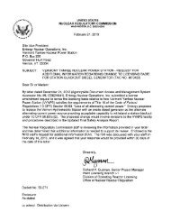
AREVA NP Inc. ANP-3203Revision 0<strong>Vermont</strong> Yankee Nuclear Power Station’s Overall Integrated <strong>Plan</strong> in Response <strong>to</strong> March 12, 2012Commission Order Modifying Licenses with Regard <strong>to</strong> Requirements <strong>for</strong> Rehable HardenedContainment Vents (Order Number EA-12-O50)Section 1: System DescriptionISG Criteria:Pace 3Licensees shall provide a complete description <strong>of</strong> the system, including important operationalResponse;characteristics. The level <strong>of</strong> detail generally considered adequate is consistent with the level <strong>of</strong> detailcontained in the licensees Final Safety Analysis Report.System Overview:The reliable Hardened Containment Vent System (HCVS) will be designed <strong>to</strong> mitigate loss-<strong>of</strong>decay-heatremoval by providing sufficient containment venting capability <strong>to</strong> limit containmentpressurization and maintain core cooling capability. The vent will be designed with sufficientcapacity <strong>to</strong> accommodate decay heat input equivalent <strong>to</strong> 19.12 MWt, which is 1% <strong>of</strong> currentlicensed thermal power (CLTP), A venting capacity sized under conditions <strong>of</strong> constant heat inputat a rate lower than 1 percent <strong>of</strong> thermal power, if required, will be justified by analysis thatprimary containment design pressure and the Primary Containment Pressure Limit (PCPL)would not be exceeded. Thus, the hardened vent capacity will be adequate <strong>to</strong> relieve decayheat <strong>for</strong> a prolonged station blackout (SBO) event. The HCVS is intended <strong>for</strong> use as oneelement <strong>of</strong> core damage prevention strategies.The HCVS flow path <strong>from</strong> the containment <strong>to</strong> an elevated release point is shown in thesimplified diagram (Figure 1) below. No ductwork will be used in the flow path.<strong>Vermont</strong> Yankee UFSAR section 2.3.6.3 states: “The “Index <strong>of</strong> Tornado Damage Potential”(defined in units <strong>of</strong> 1 000ths <strong>of</strong> 1% residential property values per year) <strong>for</strong> the tn-county area is1 as compared <strong>to</strong> a value <strong>of</strong> 33 in “<strong>to</strong>rnado alley” (Oklahoma-Kansas-Nebraska).Thom divides the United <strong>State</strong>s in<strong>to</strong> 1-degree squares and determines the <strong>to</strong>rnado frequency <strong>for</strong>each square. Using data <strong>from</strong> 1953-62, Thom records 12 <strong>to</strong>rnadoes occurring within a 1-degreesquare (about 3 million acres) encompassing the Vernon site. A mean recurrence interval <strong>for</strong> a<strong>to</strong>rnado striking a point within this 1 -degree square was calculated <strong>to</strong> be 1040 years.This seems reasonable if one considers that only 12 <strong>to</strong>rnadoes were reported in about 3 millionacres in a 10-year period.<strong>Vermont</strong> Yankee UFSAR section 12.2.1 states: “The maximum anticipated wind velocity that isanticipated at the site is 80 mph with gusts <strong>to</strong> 100 mph... The site is located in a geographicarea which has a small probability <strong>of</strong> being subjected <strong>to</strong> <strong>to</strong>rnadic wind conditions”.<strong>Vermont</strong> Yankee UFSAR section 12.2.1 lis the class I structures that have been designed <strong>to</strong>withstand short-term <strong>to</strong>rnado winds up <strong>to</strong> 300 mph. The plant stack is a Class I structure but notlisted <strong>to</strong> withstand short-term <strong>to</strong>rnado winds.
.--AREVA NP Inc. ANP-3203Revision 0<strong>Vermont</strong> Yankee Nuclear Power StatioWs Overall Integrated <strong>Plan</strong> in Response <strong>to</strong> March 12, 2012Commission Order Modifying Licenses with Regard <strong>to</strong> Requirements <strong>for</strong> <strong>Reliable</strong> HardenedContainment Vents (Order Number EA-12-O50)Paoe 4Figure 1: Simplified Vent Line Connections <strong>to</strong> Wetwell and Other Systems-./-///-./•STACK/ //New CIV2New CIV1SGT SGT78.*0 *0-38 -3*Th -WfEL -Standby GasTreatmentSystemEquipment and components:The following equipment and components will be provided:i. HCVS Mechanical Components —a) Containment isolation piping, valves and controls - The HCVS vent piping andsupports up <strong>to</strong> and induding the second containment isolation will be designed in
AREVA NP Inc. ANP-3203Revision 0<strong>Vermont</strong> Yankee Nuclear Power Stahon’s Overall Integrated <strong>Plan</strong> in Response <strong>to</strong> March 12, 2012Commission Order Modifying Licenses with Regard <strong>to</strong> Requirements <strong>for</strong> <strong>Reliable</strong> HardenedContainment Vents (Order Number EA-12-050)Page 5accordance with the existing plant design basis. Containment isolation valvesare provided consistent with the plant’s containment isolation valve design basis.The existing mo<strong>to</strong>r operated valve and rupture disk will be replaced by new CIVvalves. These valves will be air-operated valves (AOV) [Normally closed, failclosed] with DC powered solenoid valves (SOy), and can be operated <strong>from</strong>switches in the Main Control Room (MCR).b) Other system valves and piping -TheHCVS piping and supports downstream <strong>of</strong><strong>of</strong> the second containment isolation valve, including valve actua<strong>to</strong>r pneumaticsupply components, will be designed/analyzed <strong>to</strong> con<strong>for</strong>m <strong>to</strong> the requirementsconsistent with the applicable design codes <strong>for</strong> the plant and <strong>to</strong> ensurefunctionality following a design basis earthquake.C) Interface valves will provide positive isolation <strong>to</strong> the interconnected systems. TheHCVS shares part <strong>of</strong> its flow path with the Standby Gas Treatment System(SGTS). The vent pipe is connected <strong>to</strong> a <strong>to</strong>rus-<strong>to</strong>-drywell vacuum breaker line a<strong>to</strong>ne end and <strong>to</strong> the 12” SGTS line downstream <strong>of</strong> the SGTS skids at the otherend. Check valves prevent back flow <strong>from</strong> the hardened vent line in<strong>to</strong> the SGTS.iL Instrumentation <strong>to</strong> moni<strong>to</strong>r the status <strong>of</strong> the HCVS —a) Instrumentation indications will be available in both the Main Control Room andremote panel located in the diesel genera<strong>to</strong>r room.b) The location <strong>of</strong> the effluent radiation moni<strong>to</strong>r <strong>of</strong> the vent pipe will be downstreamthe second the Isolation Valve, inside the Reac<strong>to</strong>r Building. The measurementlocation (inside or outside the vent pipe) will be determined in the detailed designphase.C) HCVS vent flow path valves position indication, temperature and pressureinstrumentation will moni<strong>to</strong>r the status <strong>of</strong> the HCVS <strong>to</strong> aid the opera<strong>to</strong>r <strong>to</strong> ensureverification <strong>of</strong> proper venting operation. A failure <strong>of</strong> the position indicationinstrumentation would not prevent opening and closing the valve.d) Local instrumentation will indicate pressure <strong>of</strong> nitrogen backup cylinders.e) Existing pressure indication <strong>for</strong> the Wetwell and Drywell along with temperatureand level indication <strong>for</strong> the Wetwell will aid the opera<strong>to</strong>r <strong>to</strong> ensure proper ventingoperation.iii. Support systems —a) Normal power <strong>for</strong> the HCVS valve solenoids will be provided <strong>from</strong> the existingessential 125 VDC batteries.b) Back-up power <strong>for</strong> instrumentation on the remote control station located in thediesel genera<strong>to</strong>r room is provided <strong>from</strong> the alternate shutdown safety related BAS-2 battery system <strong>for</strong> at least 24 hours.c) Motive air/gas supply <strong>for</strong> HCVS operation will be adequate <strong>for</strong> at least the first 24hours during operation under prolonged SBO conditions, and is provided <strong>from</strong>
AREVA NP Inc.ANP-3203Revision 0<strong>Vermont</strong> Yankee Nuclear Power Station’s Overall Integrated <strong>Plan</strong> in Response <strong>to</strong> March 12, 2012Commission Order Modifying Licenses with Regard <strong>to</strong> Requirements <strong>for</strong> <strong>Reliable</strong> HardenedContainment Vents The CIVs will be operated in accordance with Emergency Operating Procedures(EOP) <strong>to</strong> control containment pressure. The HCVS will be designed <strong>for</strong>approximately 28 open/close cycles under prolonged SBO conditions. Controlledventing will be permitted iii the revised EOPs. A venting strategy will bedeveloped commensurate with the detailed design and associated analysis. Thecontrol circuit <strong>for</strong> the new vent ClVs will allow <strong>for</strong> manual override operation <strong>of</strong>the HCVS <strong>from</strong> its control panel regardless <strong>of</strong> the containment isolation signal.b) Passive: No passive component (e.g. rupture disk> will be installed.
AREVA NP Inc. ANP-3203Revision 0<strong>Vermont</strong> Yankee Nuclear Power Station’s Overall Integrated <strong>Plan</strong> in Response <strong>to</strong> March 12, 2012Commission Order Modifying Licenses with Regard <strong>to</strong> Requirements <strong>for</strong> <strong>Reliable</strong> HardenedContainment Vents (Order Number EA-12-050)Pafle 7Section 2: Design ObjectiveReguirement tl.1 -Minimizethe Reliance on Opera<strong>to</strong>r ActionsThe HCVS shall be designed <strong>to</strong> minimize the reliance on opera<strong>to</strong>r actions.ISG 1.1.1 Criteria:Ounng events that significantly challenge plant operations, individual opera<strong>to</strong>rs are more prone <strong>to</strong> humanerror. In addition, the plant operations staff may be required <strong>to</strong> implement strategies and/or take manyconcurrent actions that further places a burden on its personnel. During the prolonged SBO condition at theFukushima Dai-ichi units, opera<strong>to</strong>rs faced many significant challenges while attempting <strong>to</strong> res<strong>to</strong>re numerousplant systems that were necessary <strong>to</strong> cool the reac<strong>to</strong>r core, including the containment venting systems. Thedifficulties faced by the opera<strong>to</strong>rs related <strong>to</strong> the location <strong>of</strong> the HCVS valves, ambient temperatures andradiological conditions, loss <strong>of</strong> all alternating current electrical power, loss <strong>of</strong> motive <strong>for</strong>ce <strong>to</strong> open the ventvalves, and exhausting dc battery power. The <strong>NRC</strong> staff recognizes that opera<strong>to</strong>r actions will be needed <strong>to</strong>operate the HCVS valves, however, the licensees shall consider design features <strong>for</strong> the system that willminimize the need and reliance on opera<strong>to</strong>r actions <strong>to</strong> the extent possible dunng a variety <strong>of</strong> plantconditions, as further discussed in this ISG.The HCVS shall be designed <strong>to</strong> be operated <strong>from</strong> a control panel located in the main control room or aremote but readily accessible location. The HCVS shall be designed <strong>to</strong> be fully functional and self sufficientwith permanently installed equipment in the plant, without the need <strong>for</strong> portable equipment or connectingthere<strong>to</strong>, until such time that additional on—site or <strong>of</strong>f-site personnel and portable equipment becomeavailable. The HCVS shall be capable <strong>of</strong> operating in this mode (La., relying on permanently installedequipment) <strong>for</strong> at least 24 hours during the prolonged SBO, unless a shorter period isjustitied by thelicensee. The HCVS operation in this mode depends on a variety <strong>of</strong> conditions, such as the cause <strong>for</strong> theSBO (eg, seismic event, flood, <strong>to</strong>rnado, high winds), severity <strong>of</strong> the event, and time required <strong>for</strong> additionalhelp <strong>to</strong> reach the plant move portable equipment in<strong>to</strong> place, and make connections <strong>to</strong> the HCVS.When evaluating licensee justification <strong>for</strong> periods less than 24 hours the <strong>NRC</strong> staff will consider the number<strong>of</strong> actions and the cumulative demand on personnel resources that are needed <strong>to</strong> maintain HCVSfunctionality (eg., installation <strong>of</strong> portable equipment dunng the first 24 hours <strong>to</strong> res<strong>to</strong>re power <strong>to</strong> the HCVScontrols and/or instrumentation) as a result <strong>of</strong> design limitations. For example, the use <strong>of</strong> supplementalportable power sources may be acceptable if the suppfemental power was readily available, could be quicklyand easily moved in<strong>to</strong> place, and installed through the use <strong>of</strong> pre-engineered quick disconnects, and thenecessary human actions were identified along with the time needed <strong>to</strong> complete those actions.Conversely, supplemental power sources located in an unattended warehouse that require a qualifiedelectrician <strong>to</strong> temporarily wire in<strong>to</strong> the panel would not be considered acceptable by the staff because itsinstallation requires a series <strong>of</strong> complex, time-consuming actions in order <strong>to</strong> achieve a successful outcome.There are similar examples that could apply <strong>to</strong> mechanical systems, such as pneumatic/compressed airsystems.Response (ref. ISG Item 1.1,1):The operation <strong>of</strong> the HCVS will be designed <strong>to</strong> minimize the reliance on opera<strong>to</strong>r actions inresponse <strong>to</strong> hazards identified in NEI 12-06, Diverse and Flexible Coping Strategies (FLEX)Implementation Guide. Immediate opera<strong>to</strong>r actions can be completed by Reac<strong>to</strong>r Opera<strong>to</strong>rsand include remote-manual initiation <strong>from</strong> the HCVS remote control station. The opera<strong>to</strong>ractions required <strong>to</strong> open a vent path are:
AREVA NP ANP-3203Revision 0<strong>Vermont</strong> Yankee Nuclear Power Station’s Overall Integrated <strong>Plan</strong> in Response <strong>to</strong> March 12, 2012Commission Order Modifying Licenses with Regard <strong>to</strong> Requirements <strong>for</strong> <strong>Reliable</strong> HardenedContainment Vents (Order Number EA-12-050)Paae 8Opera<strong>to</strong>r ActionsNecessary <strong>to</strong> Vent the Containment during an SBOVent containment with Vent containment with containmentcontainment pressure at pressure as specified <strong>from</strong> remotespecified pressure <strong>from</strong> MCR control location in case MCR or DCpower is unavailable1. Open 1st containment 1. Align valves at remote panel <strong>for</strong>Isolation Valve <strong>from</strong> MCR manual operation <strong>of</strong> CIVs.2. Open 2 containment 2. Open 1St containment IsolationIsolation Valve <strong>from</strong> MCR Valve <strong>from</strong> remote panel3. Moni<strong>to</strong>r electrical power 3. Open 2 containment Isolationstatus, pneumatic pressure and Valve <strong>from</strong> remote panelcontainment I HCVS conditions4, Moni<strong>to</strong>r electrical power status,pneumatic pressure andcontainment / HCVS conditionsRemote-manual is defined in this report as a non-au<strong>to</strong>matic power operation <strong>of</strong> a componentand does not require the opera<strong>to</strong>r <strong>to</strong> be at or in close proximity <strong>to</strong> the component. No otheropera<strong>to</strong>r actions are required <strong>to</strong> initiate venting under primary procedural pro<strong>to</strong>col.The HCVS will be designed <strong>to</strong> allow initiation, control, and moni<strong>to</strong>ring <strong>of</strong> venting <strong>from</strong> the MainControl Room> and a backup remote control station in the diesel genera<strong>to</strong>r room. This locationminimizes plant opera<strong>to</strong>rs’ exposure <strong>to</strong> adverse temperature and radiological conditions and isprotected <strong>from</strong> hazards assumed in NEI 12-06.Permanently installed power and motive air/gas supply will be available <strong>to</strong> support operationand moni<strong>to</strong>ring <strong>of</strong> the HCVS <strong>for</strong> 24 hours. Permanently installed and FLEX equipment willsupply air and power <strong>to</strong> HCVS <strong>for</strong> 24 hours. The response <strong>to</strong> <strong>NRC</strong> EA-12-049 will describe indetail the FLEX ef<strong>for</strong>ts <strong>to</strong> maintain the power source. As described in NEI 12-06, allowance isprovided <strong>for</strong> opera<strong>to</strong>r actions <strong>to</strong> res<strong>to</strong>re power. Staffing studies when completed in response <strong>to</strong><strong>NRC</strong> EA-12-049 will demonstrate that sufficient manpower is available <strong>to</strong> ensure thatsupplemental DC control power can be established.After 24 hours, available personnel will be able <strong>to</strong> connect supplemental motive air/gas <strong>to</strong> theHCVS. Connections <strong>for</strong> supplementing electrical power and motive air/gas required <strong>for</strong> HCVSwill be located in accessible areas with reasonable protection per NEI 12-06 that minimizespersonnel exposure <strong>to</strong> adverse conditions following a prolonged SBO and venting. Connectionswill be pre-engineered quick disconnects <strong>to</strong> minimize manpower resources.Requirement 1.1.2 -Minimize<strong>Plan</strong>t Opera<strong>to</strong>rs’ Exposure <strong>to</strong> Occupational HazardsThe HCVS shall be designed <strong>to</strong> minimize plant opera<strong>to</strong>is’ exposure <strong>to</strong> occupational hazards, such asextreme heat stress, while operating the HCVS system.
AREVA NP Inc. ANP-3203Revision 0<strong>Vermont</strong> Yankee Nuclear Power Station’s Overall Integrated <strong>Plan</strong> in Response <strong>to</strong> March 12, 2012Commission Order Modifying Licenses with Regard <strong>to</strong> Requirements <strong>for</strong> <strong>Reliable</strong> HardenedContainment Vents (Order Number EA-12-050)Page 9ISG 1.1.2 Criteria:During a prolonged SBO. the drywell, wetwell (<strong>to</strong>rus), and nearby areas in the plant where HVCScomponents are expected <strong>to</strong> be located will likely experience an excursion in temperatures due <strong>to</strong>inadequate containment cooling combined with loss <strong>of</strong> normal and emergency building ventilation systems.In addition, installed normal and emergency lighting in the plant may not be available. Ucensees should takein<strong>to</strong> consideration plant conditions expected <strong>to</strong> be experienced during applicable beyond design basisexternal events when locating valves, instrument air supplies, and other components that will be required <strong>to</strong>safely operate the HCVS system. Components required <strong>for</strong> manual operation should be placed in areas thatare readily accessible <strong>to</strong> plant opera<strong>to</strong>rs, and not require additional actions, such as the installation <strong>of</strong>ladders or temporary scaffolding, <strong>to</strong> operate the system.When developing a design strategy, the <strong>NRC</strong> staff expects licensees <strong>to</strong> analyze potential plant conditionsand use its acquired knowledge <strong>of</strong> these areas, in terms <strong>of</strong> how temperatures would react <strong>to</strong> extended SBOconditions and the lighting that would be available during beyond design basis external events. Thisknowledge also provides an input <strong>to</strong> system operating procedures, training, the choice <strong>of</strong> protective clothing,required <strong>to</strong>ols and equipmen1. and portable lighting.Response (ref. ISG Item 1.1.2):The HCVS design allows initiating and then operating and moni<strong>to</strong>ring the HCVS <strong>from</strong> the MainControl Room and the backup remote control station in the diesel genera<strong>to</strong>r room, whichminimizes plant opera<strong>to</strong>rs’ exposure <strong>to</strong> adverse temperature and radiological conditions and theMain Control Room and diesel genera<strong>to</strong>r room, is protected <strong>from</strong> hazards assumed in NEI 12-06.Procedures will not require access <strong>to</strong> suppression pool (wetwell) area and exposure <strong>to</strong> extremeoccupational hazards <strong>for</strong> normal and backup operation <strong>of</strong> electrical and pneumatic systems.Connections <strong>for</strong> supplemental equipment needed <strong>for</strong> sustained operation will be located inaccessible areas protected <strong>from</strong> severe natural phenomena and minimize exposure <strong>to</strong>occupational hazards. Tools required <strong>for</strong> sustained operation, such as portable headlamps / orspecify lighting alternatives will be pre-staged, as necessary, in by NEI 12-06 defined s<strong>to</strong>ragelocations.Neither temporary ladders nor scaffold are required <strong>to</strong> access these connections or s<strong>to</strong>ragelocations.Requirement 1.1.3 -MinimizeRadiological ConseauencesThe HCVS shall also be designed <strong>to</strong> minimize radiological consequences that would impede personnelactions needed <strong>for</strong> event response.ISG 1.1.3 Criteria:The design <strong>of</strong> the HCVS should take in<strong>to</strong> consideration the radiological consequences resulting <strong>from</strong> theevent that could negatively impact event response, During the Fukushima event, personnel actions <strong>to</strong>manually operate the vent valves were impeded due <strong>to</strong> the location <strong>of</strong> the valves in the <strong>to</strong>rus moms. TheHCVS shall be designed <strong>to</strong> be placed in operation by opera<strong>to</strong>r actions at a control panel, located in the maincontrol room or in a remote location. The system shall be deigned <strong>to</strong> function in this mode with permanentlyinstalled equipment providing electrical power (e.g., dc power batteries) and valve motive <strong>for</strong>ce (e.g., N2/aircylinders). The system shall be designed <strong>to</strong> function in this mode <strong>for</strong> a minimum duration <strong>of</strong> 24 hours withno opera<strong>to</strong>r actions required or credited, other than the system initiating actions at the control panel.Durations <strong>of</strong> less than 24 hours will be considered ifjustified by adequate supporting in<strong>for</strong>mation <strong>from</strong> thelicensee. To ensure continued operation <strong>of</strong> the HCVS beyond 24 hours, licensees may credit manualactions such as moving portable equipment <strong>to</strong> supplement electrical power and valve motive powersources.
AREVA NP Inc. ANP-3203Revision 0<strong>Vermont</strong> Yankee Nuclear Power Station’s Overall Integrated <strong>Plan</strong> in Response <strong>to</strong> March 12, 2012Commission Order Modifying Licenses with Regard <strong>to</strong> Requirements <strong>for</strong> <strong>Reliable</strong> HardenedContainment Vents (Order Number EA-12-050)Page 10In response <strong>to</strong> Generic <strong>Letter</strong> (GL) 89-16, a number <strong>of</strong> facilities with MarkIcontainments installed ventvalves in the <strong>to</strong>rus ,oom, near the drywall, or both. Licensees can continue <strong>to</strong> use these venting locations orselect new locations, provided the requirements <strong>of</strong> this guidance document are satisfied. The HCVSimproves the chances <strong>of</strong> core cooling by removing heat <strong>from</strong> containment and Iowenng containmentpressure, when core cooling is provided by other systems. if core cooling were <strong>to</strong> fail and result in the onsetcore damage, closure <strong>of</strong> the vent valves may become necessary if the system was not designed <strong>for</strong> severeaccident service. In addition, leakage <strong>from</strong> the HCVS within the plant and the location <strong>of</strong> the external release<strong>from</strong> the HCVS could impact the event response <strong>from</strong> on-site opera<strong>to</strong>rs and <strong>of</strong>f-site help am ving at the plant.An adequate strategy <strong>to</strong> minimize radiological consequences that could impede personnel actions shouldinclude the following:1. Licensees shall provide permanent radiation shielding where necessary <strong>to</strong> facilitate personnel access <strong>to</strong>valves and allow manual operation <strong>of</strong> the valves locally. Licensee may use alternatives such as providingfeatures <strong>to</strong> facilitate manual operation <strong>of</strong> valves <strong>from</strong> remote locations, as discussed further in this guidanceunder Requirement 1.2.2, or relocate the vent valves <strong>to</strong> areas that are significantly less challenging <strong>to</strong>opera<strong>to</strong>r access/actions.2. In accordance with Requirement 1.2.8, the HCVS shall be designed <strong>for</strong> pressures that are consistent withthe higher <strong>of</strong> the primary containment design pressure and the primary containment pressure limit (PCPL),as well as including dynamic loading resulting <strong>from</strong> system actuation. In addition, the system shall be leaktight.As such, ventilation duct work (i.e., sheet metal) shall not be utilized in the design <strong>of</strong> the HCVS.Licensees should per<strong>for</strong>m appropriate testing, such as hydrostatic or pneumatic testing, <strong>to</strong> establish theleak-tightness <strong>of</strong> the HCVS,3. The HCVS release <strong>to</strong> outside atmosphere shall be at an elevation higher than adjacent plant structures.Release through existing plant stacks is considered acceptable, provided the guidance under Requirement1.2.6 is satisfied. If the release <strong>from</strong> HCVS is through a vent stack different than the plant stack theelevation <strong>of</strong> the stack should be higher than the nearest building or structure.Response (ref. ISG Item 1.1.3):The HCVS will be designed <strong>for</strong> reliable remote-manual operation. Opera<strong>to</strong>rs will not be required<strong>to</strong> access the suppression pool area. The HCVS will be designed <strong>to</strong> minimize system crossflow, prevent steam flow in<strong>to</strong> unintended areas, provide containment isolation, and providereliable and rugged per<strong>for</strong>mance as discussed below <strong>for</strong> Order requirements 1.2.6.Dose rates are evaluated consistent with the assumption that the HCVS is <strong>to</strong> be used <strong>for</strong> theprevention <strong>of</strong> core damage. Shielding or other alternatives <strong>to</strong> facilitate manual actions are notrequired <strong>for</strong> operation <strong>of</strong> the vent under these conditions since no core damage has occurred.
AREVA NP Inc.ANP-3203Revision 0<strong>Vermont</strong> Yankee Nuclear Power Station’s Overall Integrated <strong>Plan</strong>inResponse <strong>to</strong> MarchCommission Order Modifying Licenses with Regard <strong>to</strong> Requirements <strong>for</strong> <strong>Reliable</strong> HardenedContainment Vents (Order Number LA-I 2-050)12,2012Page11Section 3: Operational characteristicsRequirement 121- Capacity<strong>to</strong> Vent Equivalent <strong>of</strong>The HCVS shall have the capacity <strong>to</strong> vent the steam/energy equivalent <strong>of</strong> 1 percent <strong>of</strong> licensed/ratedthermal power (unless a lower value is justified by anatyses),below the pnmaiy containment design pressure.ISG 1,2.1 Criteria:1%and be able <strong>to</strong> maintain containment pressureBeyond design basis external events such a prolonged SBO could result in the loss <strong>of</strong> active containmentheat removal capability. The primary design objective <strong>of</strong> the HCVS is <strong>to</strong> provide sufficient venting capacity <strong>to</strong>prevent a longterm overpressure failure <strong>of</strong> the containment by keeping the containment pressure below theprimary containment designthe PCPL. The PCPL may be dictated by other fac<strong>to</strong>rs, suchthe maximum containment pressure at which the safety relief valves (SRV5) and the HCVS valves can beopened and closed.pressure andasThe <strong>NRC</strong> staff has determined that, <strong>for</strong> a vent sized under conditions <strong>of</strong> constant heat input at a rate equal<strong>to</strong> 1 percent <strong>of</strong> rated thermal power and containment pressure equal <strong>to</strong> the lower <strong>of</strong> the primary containmentdesign pressure the PCPL, the exhaust-flow through the vent would be sufficient <strong>to</strong> prevent thecontainment pressure <strong>from</strong> increasing. This determination is<strong>to</strong>rus suppression capacity is typically sufficient <strong>to</strong> absorb the decay heat generated during the firstthree hours following the shutdown <strong>of</strong> the reac<strong>to</strong>r with suppression pool the source <strong>of</strong> injection, thatdecay heat is typically than 1reac<strong>to</strong>r and that decay heat continues <strong>to</strong> <strong>to</strong> well under 1 percent, thereafter. Licensees shall havean auditable engineering basis <strong>for</strong> the decay heat absorbing capacity <strong>of</strong> their suppression pools, selection <strong>of</strong>venting pressure such that the HCVS will have sufficient venting capacity under such conditions <strong>to</strong> maintaincontainment pressure at or below the primary containment designthe PCPL. If required,venting capacity shall be <strong>to</strong> an appropriate level commensurate with the licensee’s ventingstrategy. Licensees may also a venting capacity sized under conditions <strong>of</strong> constant heat input at a ratelower than 1 percent <strong>of</strong> thermal power if it can be justified by analysis that primary containment designand the PCPL would not be exceeded. In where plants were granted, have applied, or plan<strong>to</strong> apply <strong>for</strong> power uprates, the licensees shall 1 thermal power corresponding <strong>to</strong> the upratedthermal power. The basis <strong>for</strong> the venting capacity shall give appropriate consideration <strong>of</strong> where venting isbeing per<strong>for</strong>med <strong>from</strong> (i.e.. wetwell or drywell) and the difference in between the d,ywell and thesuppression chamber. Vent sizing <strong>for</strong> multi-unit sites must take in<strong>to</strong> consideration simultaneous venting <strong>from</strong>all the units, and ensure that venting on one unit does not negatively impact the ability <strong>to</strong> vent on the otherunits.pressureendlessResponse (ref. ISG Item 1.2.1):The HCVS wetwell pathwillincreasedusebased on studies that have shown that theasat leastpercent <strong>of</strong> rated thermal power three hours following shutdown <strong>of</strong> thedecreaseusecasespercentpressure andpressurebe designed <strong>for</strong> venting steam/energy at a nominal capacity <strong>of</strong>the lower <strong>of</strong> thecontainment design pressure and the PCPL value.<strong>of</strong> 1912The1 %MWtthermal power at pressure <strong>of</strong> 56 psig. This pressurevalue assumes that the suppression pool pressure suppression capacity is sufficient <strong>to</strong>absorb the decay heat generated during the first 3 hours. The vent would then be able <strong>to</strong>prevent containment pressure <strong>from</strong> increasing above the containment design pressure. As partbe confirmed.<strong>of</strong> the detailed design, the duration <strong>of</strong> suppression pool decay heat absorptionThe HCVSisstrategy as describedfollows:During theinitialintended <strong>for</strong> use as one element <strong>of</strong> a comprehensive core damage preventioninthe response <strong>to</strong> <strong>NRC</strong> Order EA-12-049, which is summarized ascoping period (Phase1>,iswillinstalled plant equipment is used <strong>to</strong> maintain theessential function <strong>of</strong> core cooling by taking suction <strong>from</strong> the condensate s<strong>to</strong>rage tank via theRCIC and HPCI systems.as1 %
AREVA NP Inc. ANP-3203Revision 0<strong>Vermont</strong> Yankee Nuclear Power Station’s Overall Integrated <strong>Plan</strong> in Response <strong>to</strong> March 12, 2012Commission Order Modifying Licenses with Regard <strong>to</strong> Requirements <strong>for</strong> <strong>Reliable</strong> HardenedContainment Vents (Order Number EA-12-050)P2Qe 12During Phase 2, the primary strategy is <strong>to</strong> transfer water <strong>from</strong> the west basin <strong>to</strong> the condensates<strong>to</strong>rage tank <strong>to</strong> supplement the water available <strong>for</strong> RCIC suction and injection <strong>to</strong> cool the core.For Phase 3 the reac<strong>to</strong>r core cooling strategy is <strong>to</strong> place one loop <strong>of</strong> RHR in<strong>to</strong> service. This willbe accomplished by powering up a 4160V Class 1E Switchgear Bus <strong>for</strong> RHR and RHR ServiceWater pumps by utilizing a 4160V RRC FLEX portable diesel genera<strong>to</strong>r and supplying the RHRHeat Exchanger with water <strong>from</strong> the cooling <strong>to</strong>wer deep basin using the RHR Service Waterpumps and existing Alternate Cooling System piping.
AREVA NP Inc. ANP-3203Revision 0<strong>Vermont</strong> Yankee Nuclear Power Station’s Overall Integrated <strong>Plan</strong> in Response <strong>to</strong> March 12, 2012Commission Order Modifying Licenses with Regard <strong>to</strong> Requirements <strong>for</strong> <strong>Reliable</strong> HardenedContainment Vents (Order Number LA-I 2-050)ReQuirement 1.2.2 - HCVS Shall be Accessible <strong>to</strong> <strong>Plan</strong>t Opera<strong>to</strong>rsPage 13The HCVS shall be accessible <strong>to</strong> plant opera<strong>to</strong>rs and be capable <strong>of</strong> remote operation and control, or manualoperation, during sustained operations.ISG 1.2.2 Criteria:The preferred location <strong>for</strong> remote operation and control <strong>of</strong> the HCVS is <strong>from</strong> the main control room However,alternate locations <strong>to</strong> the control room are also acceptable, provided the licensees take in<strong>to</strong> consideration thefollowing:1.Sustained operations mean the ability <strong>to</strong> open/close the valves multiple times during the event. Licenseesshall determine the number <strong>of</strong> open/close cycles necessary during the first 24 hours <strong>of</strong> operation andprovide supporting basis consistent with the plant-specific containment venting strategy.2. An assessment <strong>of</strong> temperature arid radiological conditions that operating personnel may encounter both intransit and locally at the controls Licensee may use alternatives such as providing features <strong>to</strong> facilitatemanual operation <strong>of</strong> valves <strong>from</strong> remote locations or relocahng/reorienting the valves.3 All permanently installed HCVS equipment, including any connections required <strong>to</strong> supplement the HCVSoperation dunng a prolonged SBO (electric power N2/air) shall be located above the maximum designbasis external flood level or protected <strong>from</strong> the design basis external flood.4 During a prolonged SBO, manual operation/action may become necessary <strong>to</strong> operate the HCVS Asdemonstrated during the Fukushima event, the valves lost motive <strong>for</strong>ce including electric power andpneumatic air supply <strong>to</strong> the valve opera<strong>to</strong>rs, and control power <strong>to</strong> solenoid valves If direct access andlocal operation <strong>of</strong> the valves is not feasible due <strong>to</strong> temperature or radiological hazards, licensees shouldinclude design features <strong>to</strong> facilitate remote manual operation <strong>of</strong> the HCVS valves by means such as reachrods, chain links, hand wheels, and portable equipment <strong>to</strong> provide motive <strong>for</strong>ce (e g., air/N2 bottles, dieselpowered compressors, and dc batteries). The connections between the valves and portable equipmentshould be designed <strong>for</strong> quick deployment If a portable motive <strong>for</strong>ce (e g., air or N2 bottles, dc powersupplies) is used in the design strategy, licensees shall provide reasonable protection <strong>of</strong> that equipmentconsistent with the staffs guidance delineated in JLD-ISG-2012-O1 <strong>for</strong> Order EA-12-0495 The design shall preclude the need <strong>for</strong> opera<strong>to</strong>rs <strong>to</strong> move temporary ladders or operate <strong>from</strong> a<strong>to</strong>pscaffolding <strong>to</strong> access the HCVS valves or remote operating locationsResponse (ref. ISG Item 1.2.2):The HCVS design allows initiating and then operating and moni<strong>to</strong>ring the HCVS <strong>from</strong> the MainControl Room and the backup remote control station in the diesel genera<strong>to</strong>r room. Thislocation is also protected <strong>from</strong> adverse natural phenomena.1. The HCVS flow path valves are air-operated valves (AOV) with air-<strong>to</strong>-open and spring<strong>to</strong>-shut.Opening the valves requires energizing a DC powered solenoid operated valve(SOV) and providing motive air/gas. The detailed design will provide a permanentlyinstalled DC power source <strong>for</strong> the solenoids.Power <strong>for</strong> the instrumentation on the remote control station in the diesel genera<strong>to</strong>r roomwill be provided <strong>from</strong> the existing alternate shutdown safety related B-AS2 batteryadequate <strong>for</strong> the first 24 hours. Also motive air/gas adequate <strong>for</strong> the first 24 will beprovided <strong>to</strong> the remote control station. FLEX will be credited after the fIrst 24 hours.The response <strong>to</strong> <strong>NRC</strong> EA-1 2-049 will demonstrate the capability under the FLEX ef<strong>for</strong>t<strong>to</strong> maintain the DC source. The initial s<strong>to</strong>red motive air/gas will allow <strong>for</strong> a minimum <strong>of</strong>approximately 28 valve operating cycles; however, the detailed design will determine thenumber <strong>of</strong> required valve cycles <strong>for</strong> the first 24-hours and the initial s<strong>to</strong>red motive air/gas
AREVA NP Inc. ANP-3203Revision 0<strong>Vermont</strong> Yankee Nuclear Power Station’s Overall Integrated <strong>Plan</strong> in Response <strong>to</strong> March 12, 2012Commission Order Modifying Licenses with Regard <strong>to</strong> Requirements <strong>for</strong> <strong>Reliable</strong> HardenedContainment Vents (Order Number EA-12-O5O)Page 14will support the required number <strong>of</strong> valve cycles. The SOVs are the only electricalcomponents required <strong>for</strong> valve functionality that are located inside the area considerednot-accessible following a prolonged 880. The AOVs do not require <strong>to</strong>rque switchesand limit switches <strong>to</strong> operate. The limit switches will only be used <strong>for</strong> position indication.Backup manual operation <strong>from</strong> the remote control station allows <strong>for</strong> opening the AOVswithout DC power by bypassing the SOVs and directly supplying nitrogen <strong>to</strong> the valveactua<strong>to</strong>rs.2. An assessment <strong>of</strong> temperature and radiological conditions that operating personnel mayencounter both in transit and locally at the controls will be per<strong>for</strong>med,3. All permanently installed HCVS equipment, including any connections required <strong>to</strong>supplement the HCVS operation during a prolonged SBO (electric power,N2/air) will belocated in areas reasonably protected <strong>from</strong> defined hazards <strong>from</strong> NEI 12-06.4. All valves required <strong>to</strong> open the flow path are designed <strong>for</strong> remote manual operationfollowing a prolonged SBO, i.e., no valve operation via handwheel, reach—rod or similarmeans that requires close proximity <strong>to</strong> the valve. Any supplemental connections will bepre-engineered <strong>to</strong> minimize manpower resources and any needed portable equipmentwill be reasonably protected <strong>from</strong> defined hazards <strong>from</strong> NEI1 2-06.5. Access <strong>to</strong> the locations described above will not require temporary ladders orscaffolding.6. A manual override motive gas system will be permanently installed <strong>to</strong> supply motive gas<strong>to</strong> the HCVS ClVs <strong>to</strong> address loss <strong>of</strong> power <strong>to</strong> the DC SOVs. The nitrogen pneumaticsupply will be connected in parallel with the existing pneumatic supply <strong>to</strong> manually cyclethe ClVs. The manual operation will be per<strong>for</strong>med <strong>from</strong> the remote control stationlocated in the accessible diesel genera<strong>to</strong>r room.Requirement 1.2.3 - Prevent Inadvertent ActuationThe HCVS shall include a means <strong>to</strong> prevent inadvertent actuation.ISG 1.2.3 Criteria:The design <strong>of</strong> the HCVS shall incorporate features, such as control panel key-locked switches, lockingsystems, rupture discs, or administrative controls <strong>to</strong> prevent the inadvertent use <strong>of</strong> the vent valves. Thesystem shall be designed <strong>to</strong> preclude inadvertent actuation <strong>of</strong> the HCVS due <strong>to</strong> any single active failure. Thedesign should consider general guidelines such as single point vulnerability and spurious operations <strong>of</strong> anyplant installed equipment associated withHCVS.The objective <strong>of</strong> the HCVS is <strong>to</strong> provide sufficient venting <strong>of</strong> containment and prevent long-termoverpressure failure <strong>of</strong> containment following the loss <strong>of</strong> active containment heat removal capability orprolongedSBC),Howeve,, inadvertent actuation <strong>of</strong> HCVS due <strong>to</strong> a design error equ,Øment malfunction, oropera<strong>to</strong>r error during a design basis loss-<strong>of</strong>-coolant accident (DBLOCA) could have an undesirable effect onthe containment accidentpressure (CAP) <strong>to</strong> provide adequate net positive suction head <strong>to</strong> the emergencycore cooling system (ECCS) pumps. There<strong>for</strong>e, prevention <strong>of</strong> inadvertent actuation, while important <strong>for</strong> allplants, is essential <strong>for</strong> plants relying on CAP. The licensee submittals on HCVS shall specifically includedetails on how this issuerequiredwill be addressed on their individual plants <strong>for</strong> all situations when CAP credit is
AREVA NP Inc.ANP-3203Revision0<strong>Vermont</strong> Yankee Nuclear Power Station’s Overall Integrated <strong>Plan</strong>inResponse <strong>to</strong> MarchCommission Order Modifying Licenses with Regard <strong>to</strong> Requirements <strong>for</strong> <strong>Reliable</strong> HardenedContainment Vents (Order Number EA-12-050)Response(ref.l$G Item 1.2.3):The HCVS containment isolation valves are normally closed AOVs that are air-<strong>to</strong>-open andspring-<strong>to</strong>-shut. TheDCMCR switch <strong>for</strong> each <strong>of</strong> the two in-series valvessame DC and motive air source12,2012PageSOV must be energized <strong>to</strong> allow the motive air <strong>to</strong> open the valve. Thewillwillhave a key-locked switch. Although thebe used, separate control circuits including switchesused <strong>for</strong> the two redundant valves <strong>to</strong> address single point vulnerabilities that may cause thepath <strong>to</strong> inadvertently open.The features that prevent inadvertent actuation are administrative controls and key lockswitchesstationinisthe MCR <strong>for</strong> the two ClVsinseries. Inadvertent action <strong>from</strong> the remote controlprevented by administrative controls and several manual steps <strong>to</strong> open the CIVs.Emergency operating procedures and Severe Accident Guidelines (SAG) provide clearguidance that the HCVS is not <strong>to</strong> be used <strong>to</strong> defeat containment integrity during any designbe designed <strong>to</strong> provide features <strong>to</strong>prevent inadvertent actuation due <strong>to</strong> a design error, equipment malfunction, or opera<strong>to</strong>r error,basis transients and accidents.Inaddition, the HCVSthat would provide net positivesuction head <strong>to</strong> the emergency core cooling system (ECCS) pumpssuch that any credited containment accident pressurewill(CAP>willbe15willflowbe available (inclusive<strong>of</strong> a design basis loss-<strong>of</strong>-coolant accident (DBLOCA)). For the long term DBLOCA, credit <strong>for</strong>suppression pool accident pressureiscredited <strong>to</strong> ensure adequate available NPSH <strong>for</strong> RHRand CS pumps. For Appendix R and SBO, credit <strong>for</strong> containment pressure is not required <strong>to</strong>ensure adequate RHR and CS pump NPSH.Requirement 1.2.4- Moni<strong>to</strong>rthe Status <strong>of</strong> the Vent SystemThe HCVS shall include a means <strong>to</strong> moni<strong>to</strong>r the status <strong>of</strong> the vent system (e.g., valve position indication)<strong>from</strong> the control room or other location(s). The moni<strong>to</strong>ring system shall be designed <strong>for</strong>dunng a prolonged SBO.ISG 1.2.4 Criteria:sustained operation<strong>Plan</strong>t opera<strong>to</strong>rs must be able <strong>to</strong> readily moni<strong>to</strong>r the <strong>of</strong> the HCVS at all times, including being able <strong>to</strong>understand whether or not containment pressure/energy is being vented through the HCVS,not containment integrity been res<strong>to</strong>red following venting operations, Licensees shall provide a means<strong>to</strong> allow plant opera<strong>to</strong>rs <strong>to</strong> readily determine, or have knowledge the foliowing system parameters:has(1) HCVS vent valves’ position (open or closed),(2) system pressure,and(3) effluent temperature.statusoland whether orOther important in<strong>for</strong>mation includes the status <strong>of</strong> supporting systems, such availability <strong>of</strong> electrical powerand pneumatic supply pressure. Moni<strong>to</strong>ring by means <strong>of</strong> pennanently installed gauges that aL or nearby,the HCVS control panel is acceptable. The staff will consider alternative approaches <strong>for</strong> system statusinstrumentation; howevei licensees must provide sufficient in<strong>for</strong>mation justification <strong>for</strong> alternativeapproaches.The means <strong>to</strong> moni<strong>to</strong>r system status shall support sustained operations during a prolonged SBO, and bedesigned <strong>to</strong> operate under potentially harsh environmental conditions that woiJd be expected following aloss <strong>of</strong> containment heat removal capability and SL3O. Power supplies <strong>to</strong> all instruments, controls,indications shall be <strong>from</strong> the same power sources supporting the HGVS operation. “Sustained operations”may include the <strong>of</strong>portable equipment <strong>to</strong> provide alternate source <strong>of</strong>power <strong>to</strong> components <strong>to</strong>moni<strong>to</strong>r HCVS status. Licensees shall demonstrate instrument reliability via an appropriate combination <strong>of</strong>useanandasareandused
AREVA NP Inc. ANP-3203Revision 0<strong>Vermont</strong> Yankee Nuclear Power Station’s Overall Integrated <strong>Plan</strong> in Response <strong>to</strong> March 12, 2012Commission Order Modifying Licenses with Regard <strong>to</strong> Requirements <strong>for</strong> <strong>Reliable</strong> HardenedContainment Vents (Order Number EA-12-050)Page 16design. analyses. operating experience, and/or testing <strong>of</strong> channel components foi the following sets <strong>of</strong>parametersaradiological conditions that the instruments may encounter under normal plant conditions, and duringand after a prolonged SBO event.• temperatures and pressure conditions as doscnbed under requirementloading <strong>from</strong> system operation.128.including dynamic• humidity based on instrument location and effluent conditionsResponse (ref. ISG Item 1.2.4):inthe HCVS.The design <strong>of</strong> the HCVS will have temperature and pressure moni<strong>to</strong>ring downstream <strong>of</strong> the lastcontainment isolation valve. All flow path valves will have open and closed position indication.These HCVS indications will be at or near the same location as the valve control switches,which is the MCR and remote control station. Motive air/gas pressure and power sourcevoltage will be moni<strong>to</strong>red (voltage <strong>for</strong> the 125 VOC station batteries can be moni<strong>to</strong>red <strong>from</strong> theDC panels located in the cable spreading room).Power <strong>for</strong> the instrumentation <strong>for</strong> the remote control station will be <strong>from</strong> the safety related B-AS2 battery, its chargers and switchgear are located in the adjacent Diesel Genera<strong>to</strong>r room.Power <strong>from</strong> essential DC batteries will be used <strong>to</strong> supply the SOVs used <strong>to</strong> position the AOVs.Refer <strong>to</strong> the response <strong>to</strong> 1.2.2 <strong>for</strong> discussion on the power.The approximate range <strong>for</strong> the temperature indication will be 50°F <strong>to</strong> 600°F. The approximaterange <strong>for</strong> the pressure indication will be 0 psig <strong>to</strong> 120 psig. The upper limits are approximatelytwice the required design containment temperature and pressure. The ranges will be finalizedwhen the detailed design and equipment specifications are prepared.The detailed design will address the radiological, temperature, pressure, flow induced vibration(if applicable) and internal piping dynamic <strong>for</strong>ces, humidity/condensation and seismicqualification requirements. Assumed radiological conditions are those expected after aprolonged SBO (without fuel failure), which will bound normal plant conditions.Requirement 1.2.5- Moni<strong>to</strong>rthe Effluent Discharge <strong>for</strong> RadioactivityThe HCVS shall include a means<strong>from</strong> operation <strong>of</strong> the HCVS The moni<strong>to</strong>ring system shall provide indication<strong>to</strong> moni<strong>to</strong>r the effluent discharge <strong>for</strong> radioactiwty that may be releasedinlocation(s), and shall be designed <strong>for</strong> sustained operation during a prolonged SBO.ISG 12.5 Criteria:the control room or otherLicensees shall provide an independent means <strong>to</strong> moni<strong>to</strong>r overall radioactivity that may be released <strong>from</strong> theHCVS discharge The radiation moni<strong>to</strong>r does not need <strong>to</strong> meet the requirements <strong>of</strong> NUREG 0737 <strong>for</strong>moni<strong>to</strong>red releases, nor does it need <strong>to</strong> be able moni<strong>to</strong>r releases quantitatively <strong>to</strong> ensure compliance withTitle10 <strong>of</strong> the Code <strong>of</strong> Federal Regulations (10 CFR) Pa#1(A) or 10 CFR Section. 67A wide-rangemoni<strong>to</strong>ring system <strong>to</strong> moni<strong>to</strong>r the overall activity in the release providing indication that effluent <strong>from</strong> thecontainment environment that is passing by the moni<strong>to</strong>r is acceptable The use <strong>of</strong> other existing radiationmoni<strong>to</strong>ring capabilityinlieu <strong>of</strong> an independent HCVS radiation moni<strong>to</strong>r is not acceptable because plan<strong>to</strong>pera<strong>to</strong>rs need accurate in<strong>for</strong>mation about releases coming <strong>from</strong> the containment via the HCVS in order <strong>to</strong>make in<strong>for</strong>med decisions on operation <strong>of</strong> the reliable hardened venting system
AREVA NP Inc.ANP-3203Revision 0<strong>Vermont</strong> Yankee Nuclear Power StatioWs Overall Integrated <strong>Plan</strong> in Response <strong>to</strong> March 12, 2012Commission Order Modifying Licenses with Regard <strong>to</strong> Requirements <strong>for</strong> <strong>Reliable</strong> HardenedContainment Vents (Order Number EA-12-050)Page 17The moni<strong>to</strong>ring system shall provide indication in the control room or a remote location (i.e., HCVS controlpanel) <strong>for</strong> the first 24 hours <strong>of</strong> an extended 580 with electric power proiided by permanent DC batteiysources, and supplemented by portable power sources <strong>for</strong> sustained operations. Monr<strong>to</strong>nng radiation levelsis required only dunng the events that necessitate operation <strong>of</strong> the HCVS The reliability <strong>of</strong> the effluentmoni<strong>to</strong>ring system under the applicable environmental conditions shall be demonstrated by methodsdescnbed under Requirement 1 24Response (ref. ISO Item 1.2.5):The HCVS RMS (radiation moni<strong>to</strong>ring system) will be dedicated <strong>to</strong> the HCVS. The approximaterange <strong>of</strong> the radiation moni<strong>to</strong>ring system is 0.1 mrem/hr <strong>to</strong> 1000 mrem/hr. This range isconsidered adequate <strong>to</strong> determine core integrity per the <strong>NRC</strong> Responses <strong>to</strong> Public CommentsdocumentThe mounting position <strong>of</strong> the radiation detec<strong>to</strong>r will be determined in the detailed design. Theradiation level will be indicated at the MCR and remote control station. The RMS will bepowered <strong>from</strong> the same source as all other powered HCVS components, Refer <strong>to</strong> the response<strong>to</strong> 1.2,2 <strong>for</strong> discussion on sustainability <strong>of</strong> the power.Reguirement 1.2.6 - Minimize Unintended Cross Flow <strong>of</strong> Vented FluidsThe HCVS shall include design features <strong>to</strong> minimize unintended cross flow <strong>of</strong> vented fluids within a unit andbetween units on the siteISG 1.2.6 Criteria:At Fukushima, an explosion occurred in Unit 4, which was in a maintenance outage at the time <strong>of</strong> the event.Although the facts have not been fully established, a likely cause <strong>of</strong> the explosion in Unit 4 is that hydrogenleaked <strong>from</strong> Unit 3 <strong>to</strong> Unit 4 through a common venting system. System cross-connections present apotential <strong>for</strong> steam, hydrogen, and airborne radioactivity leakage <strong>to</strong> other areas <strong>of</strong> the plant and <strong>to</strong> adjacentunits at multi-unit sites if the units are equipped with common vent piping In this context, a design that isfree <strong>of</strong> physical and control interfaces with other systems eliminates the potential <strong>for</strong> any cross-flow and isone way <strong>to</strong> satisfy this requirement. Regardless, system design shall provide design features <strong>to</strong> prevent thecross flow <strong>of</strong> vented fluids and migration <strong>to</strong> other areas within the plant or <strong>to</strong> adjacent units at multi-unit sites.The current design <strong>of</strong> the hardened vent at several plants in the U. S includes cross connections with thestandby gas treatment system, which contains sheet metal ducts and filter and fan housings that are not asleak tight as hard pipes In addition, dual unit plant sites are <strong>of</strong>ten equipped with a common plant stackExamples <strong>of</strong> acceptable means <strong>for</strong> prevention <strong>of</strong> cross flow is by valves, leak-tight dampers, and checkvalves, which shall be designed <strong>to</strong> au<strong>to</strong>matically close upon the initiation <strong>of</strong> the HCVS and shall remainclosed <strong>for</strong> as long as the HCVS is in operation. License&s shall evaluate the environmental conditions (e g.pressure, temperature) at the damper locations dunng venting operations <strong>to</strong> ensure that the dampers willremain functional and sufficiently leak-tight, and if necessary replace the dampers with other suitableequipment such as valves lf power is required <strong>for</strong> the interfacing valves <strong>to</strong> move <strong>to</strong> isolation position, it shallbe <strong>from</strong> the same power sources as the vent valves Leak tightness <strong>of</strong> any such barriers shall be penodicallyverified by testing as described under Requirement 1 27Response (ref. ISO Item 1,2.6):The HCVS shares part <strong>of</strong> its flow path with the Standby Gas Treatment System (SGTS). TheHCVS ties in<strong>to</strong> the SGTS downstream the filter trains and shares the discharge pipe going <strong>to</strong>the plant stack. The SGTS is isolated <strong>from</strong> the HCVS by check valves. The detailed designphase will review the check valves <strong>to</strong> determine if the inter-system valves can meet the required
AREVA NP Inc. ANP-3203Revision 0<strong>Vermont</strong> Yankee Nuclear Power Station’s Overall Integrated <strong>Plan</strong> in Response <strong>to</strong> March 12, 2012Commission Order Modifying Licenses with Regard <strong>to</strong> Requirements <strong>for</strong> <strong>Reliable</strong> HardenedContainment Vents (Order Number EA-12-050)Page 18leakage criteria under the limiting HCVS design conditions, If required, the valves will bereplaced or upgraded.
AREVA NP Inc.ANP-3203Revision 0<strong>Vermont</strong> Yankee Nuclear Power Station’s Overall Integrated <strong>Plan</strong> in Response <strong>to</strong> March 12, 2012Commission Order Modifying Licenses with Regard <strong>to</strong> Requirements <strong>for</strong> <strong>Reliable</strong> HardenedContainment Vents (Order Number EA-12-050)ReQuirement I 27 - Provision <strong>for</strong> the Ooeration. Testing, InsDection and MaintenanceThe HCVS shall include features and provision <strong>for</strong> the operation, testing, inspection and maintenanceadequate <strong>to</strong> ensure that reliable function and capability are maintainedISG t2.7 Criteria:PajThe HCVS piping run shall be designed <strong>to</strong> eliminate the potential <strong>for</strong> condensation accumulation, assubsequent water hammer could complicate system operation during intermittent venting or <strong>to</strong> withstand thepotential <strong>for</strong> water hammer without compromising the functionality <strong>of</strong> the system. Licensees shall provide ameans (e g, drain valves, pressure and temperature gauge connections) <strong>to</strong> penodically test systemcomponents, including exercising (opening and closing) the vent valve(s) In situations where <strong>to</strong>talelimination <strong>of</strong> condensation is not feasible, HCVS shall be designed <strong>to</strong> accommodate condensation,including applicable water hammer loads.The HCVS outboard <strong>of</strong> the containment boundary shall be tested <strong>to</strong> ensure that vent flow is released <strong>to</strong> theoutside with minimal leakage, if any, through the interfacing boundaries with other systems or units.Licensees have the option <strong>of</strong> individually leak testing interfacing valves or testing the overall leakage <strong>of</strong> theHCVS volume by conventional leak rate testing methods. The test volume shall envelope the HCVSbetween the outer pnmary containment isolation barner and the vent exiting the plant buildings, including thevolume up <strong>to</strong> the interfacing valves. The test pressure shall be based on the HCVS design pressure.Permissible leakage rates <strong>for</strong> the interfacing valves shall be within the requirements <strong>of</strong> American Society <strong>of</strong>Mechanical Engineers Operation and Maintenance <strong>of</strong> Nuclear Power <strong>Plan</strong>ts Code (ASME OM) — 2009,Subsection ISTC — 3630 (e) (2,), or later edition <strong>of</strong> the ASME OM Code. When testing the HCVS volume,allowed leakage shall not exceed the sum <strong>of</strong> the interfacing valve leakages as determined <strong>from</strong> the ASMEOM Code The <strong>NRC</strong> staff will consider a higher leakage acceptance values if licensees provide acceptablejustification When reviewing such requests, the <strong>NRC</strong> staff will consider the impact <strong>of</strong> the leakage on thehabitability <strong>of</strong> the rooms and areas within the building and operability <strong>of</strong> equipment in these areas during theevent response and subsequent recovery periods. Licensees shall implement the following operation,testing and inspection requirements <strong>for</strong> the HCVS <strong>to</strong> ensure reliable operation <strong>of</strong> the systemDescnptionTesting and Inspection RequirementsCycle the HCVS valves and the interfacing systemvalves not used <strong>to</strong> maintain containment integrityduring operations.Per<strong>for</strong>m visual inspections and a walkdown <strong>of</strong>HCVS componentsTest and calibrate the HCVS radiation moni<strong>to</strong>rsLeak test the HCVSValidate the HCVS operating procedures byconducting an open/close test <strong>of</strong> the HCVScontrol logic <strong>from</strong> its control panel and ensuringthat all interfacing system valves move <strong>to</strong> theirproper (intended) positions.Once per yearFrequencyOnce per operating cycleOnce per operating cycle(1) Pnor <strong>to</strong> first declanng the systemfunctionaf(2) Once every five years thereafter, and(3) After res<strong>to</strong>ration <strong>of</strong> any breach <strong>of</strong>system boundary within the buildingsOnce per every other operating cycle
AREVA NP Inc.ANP-3203Revision 0<strong>Vermont</strong> Yankee Nuclear Power Stations Overall Integrated <strong>Plan</strong> in Response <strong>to</strong> March 12, 2012Commission Order Modifying Licenses with Regard <strong>to</strong> Requirements <strong>for</strong> <strong>Reliable</strong> HardenedContainment Vents (Order Number EA-12-O5O)Response (ref. ISG Item 1 2.7):Page 20The detailed design <strong>for</strong> the HCVS will address condensation accumulation resulting <strong>from</strong>intermittent venting. In situations where <strong>to</strong>tal elimination <strong>of</strong> condensation is not feasible, theHCVS will be designed <strong>to</strong> accommodate condensation, including allowance <strong>for</strong> applicable waterhammer loads.The HCVS Containment Isolation Valves will be tested in accordance with the licensing anddesign basis <strong>for</strong> the plant. The HCVS past the outboard Containment Isolation Valve <strong>to</strong> wherethe vent exits the plant Reac<strong>to</strong>r Building will be tested in con<strong>for</strong>mance <strong>to</strong> one <strong>of</strong> the ISGmethods. The test pressure shall be based on the HCVS design pressure with 56 psig.Permissible leakage rates <strong>for</strong> the interfacing valves will be within the requirements <strong>of</strong> AmericanSociety <strong>of</strong> Mechanical Engineers Operation and Maintenance <strong>of</strong> Nuclear Power <strong>Plan</strong>ts Code(ASME OM) — 2009 Subsection ISTC — 3630 (e) (2> or later edition <strong>of</strong> the ASME CM CodeWhen testing the HCVS volume, the allowed leakage will not exceed the sum <strong>of</strong> the interfacingvalve leakages as determined <strong>from</strong> the ASME OM Code unless a higher leakage acceptancevalue is justified <strong>to</strong> the <strong>NRC</strong>.The test types and frequencies will con<strong>for</strong>m <strong>to</strong> the ISG 1.2.7 Table “Testing and InspectionRequirements” with the clarification that “Leak test the HCVS” applies <strong>to</strong> the HCVS boundaryvalves.Requirement 1.2.8 - Design PressuresThe HCVS shall be designed <strong>for</strong> pressures that are consistent with maximum containment design pressures,as well as, dynamic loading resulting <strong>from</strong> system actuation.ISG 1.2.8 Criteria:The vent system shall be designed <strong>for</strong> the higher <strong>of</strong> the primai’y containment design pressure or PCPL. anda saturation temperature corresponding <strong>to</strong> the HCVS design pressure. However if the venting location is<strong>from</strong> the diywell, an additional margin <strong>of</strong> 50 “F shall be added <strong>to</strong> the design temperature because <strong>of</strong> thepotential <strong>for</strong> superheated conditions in the drywelt The piping, valves, and the valve actua<strong>to</strong>rs shall bedesigned <strong>to</strong> withstand the dynamic loading resulting <strong>from</strong> the actuation <strong>of</strong> the system, including pipingreaction loads <strong>from</strong> valve opening, concurrent hydrodynamic loads <strong>from</strong> SRV discharges <strong>to</strong> the suppressionpool, and potential <strong>for</strong> water hammer <strong>from</strong> accumulation <strong>of</strong> steam condensation during multiple ventingcycles.Response (ref. ISG Item 1.2.8):The HCVS design pressure is 62 psig and design temperature is 281°F. The HCVS designpressure is the higher <strong>of</strong> the containment design pressure and the PCPL value. The detaileddesign will ensure a HCVS design temperature <strong>of</strong> 309°F, corresponding <strong>to</strong> a design pressure <strong>of</strong>62 psig under saturated conditions.The piping, valves, and valve actua<strong>to</strong>rs will be designed <strong>to</strong> withstand the dynamic loadingresulting <strong>from</strong> the actuation <strong>of</strong> the HCVS, including piping reaction loads <strong>from</strong> valve opening,concurrent hydrodynamic loads <strong>from</strong> SRV discharges <strong>to</strong> the suppression pool, and potential <strong>for</strong>water hammer <strong>from</strong> accumulation <strong>of</strong> condensation during multiple venting cycles.
AREVA NP Inc.ANP-3203Revision 0<strong>Vermont</strong> Yankee Nuclear Power Station’s Overall Integrated <strong>Plan</strong> in Response <strong>to</strong> March 12, 2012Commission Order Modifying Licenses with Regard <strong>to</strong> Requirements <strong>for</strong> <strong>Reliable</strong> HardenedContainment Vents (Order Number EA-12-O5O)Requirement 12.9 - Discharge Release PointThe HCVS shall discharge the effluent <strong>to</strong> a release point above main plant structures,ISG 1.2.9 Criteria:Paae 21The HCVS release <strong>to</strong> outside atmosphere shall be at an elevation higher than adjacent plant structures.Release through existing plant stacks is considered acceptable, provided the guidance under Requirement1 2.6 is satisfied. If the release tlom HCVS is through a stack different than the plant stack, the elevation <strong>of</strong>the stack should be higher than the nearest building or structure. The release point should be situated away<strong>from</strong> ventilation system intake and exhaust openings, and emergency response facilities. The release stackor structure exposed <strong>to</strong> outside shall be designed or protected <strong>to</strong> withstand missiles that could be generatedby the external events causing the prolonged S8() (e.g., <strong>to</strong>rnadoes, high winds).Response (ref. ISG Item 1,2.9):The HCVS discharge path uses the existing plant stack.
AREVA NP Inc. ANP-3203Revision 0<strong>Vermont</strong> Yankee Nuclear Power Station’s Overall Integrated <strong>Plan</strong> in Response <strong>to</strong> March 12, 2012Commission Order Modifying Licenses with Regard <strong>to</strong> Requirements <strong>for</strong> <strong>Reliable</strong> HardenedContainment Vents (Order Number EA-12-050)Page 22Section 4: Appilcable Quality RequirementsRequirement 2.1- Containment Isolation FunctionThe HCVS system design shall not preclude the containment isolation valves, Including the vent valve <strong>from</strong>per<strong>for</strong>ming their intended containment isolation function consistent with the design basis <strong>for</strong> the plant Theseitems include piping, piping supports, containment isolation valves, containment isolation valve actua<strong>to</strong>rsand containment isolation valve position indication componentsISG 2.1 Criteria:The HCVS vent path up <strong>to</strong> and including the second containment isolation barrier shall be designedconsistent with the design basis <strong>of</strong> the plant These items include piping. piping supports, containmentisolation valves containment isolation valve actua<strong>to</strong>rs and containment isolation valve position indicationcomponents The HCVS design, out <strong>to</strong> and including the second containment isolation bamer shall meetsafety-related requirements consistent with the design basis <strong>of</strong> the plant The staff notes that in response <strong>to</strong>GL 89-16, in many cases. the HCVS vent tine connections were made <strong>to</strong> existing systems. In some cases.the connection was made in between two existing containment isolation valves and in others <strong>to</strong> the vacuumbreaker line The HCVS system design shall not preclude the containment isolation valves, including thevent valve <strong>from</strong> per<strong>for</strong>ming their intended containment isolation function consistent with the design basis <strong>for</strong>the plant. The design shall include all necessary overrides <strong>of</strong> containment isolation signals and otherinterface system signals <strong>to</strong> enable the vent valves <strong>to</strong> open upon initiation <strong>of</strong> the HCVS <strong>from</strong> its control panelResponse (ref. ISG Item 2.1):The HCVS vent path up <strong>to</strong> and including the second containment isolation piping and supportsis designed in accordance with existing design basis. The HCVS system design will notpreclude the containment isolation valves, including the vent valve, <strong>from</strong> per<strong>for</strong>ming theirintended containment isolation function consistent with the design basis <strong>for</strong> the plant.Associated actua<strong>to</strong>rs, position indication, and power supplies are designed consistent with thedesign basis <strong>of</strong> the plant as required <strong>to</strong> maintain their design basis function <strong>of</strong> maintaining thevalves closed. The control circuit will allow operation <strong>of</strong> the HCVS <strong>from</strong> its control panelregardless <strong>of</strong> containment isolation signals.Requirement 2.2 -<strong>Reliable</strong>and Rugged Per<strong>for</strong>manceAll other HCVS components shall be designed <strong>for</strong> reliable and rugged per<strong>for</strong>mance that is capable <strong>of</strong>ensuring HCVS functionality following a seismic event. These items include electncal power supply, valveactua<strong>to</strong>r pneumatic supply, and instrumentation (local and remote) componentsISG 2.2 Criteria:All components <strong>of</strong> the HCVS beyond the second containment isolation barrier shall be designed <strong>to</strong> ensureHCVS functionality following the plants design basis seismic event These components include, in addition<strong>to</strong> the hardened vent pipe, electric power supply. pneumatic suppfr and instrumentation The design <strong>of</strong>power and pneumatic supply lines between the HCVS valves and remote locations (if portable sources were<strong>to</strong> be employed) shall also be designed <strong>to</strong> ensure HCVS functionality Licensees shall ensure that the HCVSwill not impact other safety-related structures and components and that the HCVS will not be impacted bynon-seismic components. The staff prefers that the HCVS components, includuig the piping run, be locatedin seismically qualified stivctures. However, short runs <strong>of</strong> HCVS piping in non-seismic structures areacceptable if the licensee provides adequate justification on the seismic ruggedness <strong>of</strong> these structures Thehardened vent shall be designed <strong>to</strong> con<strong>for</strong>m <strong>to</strong> the requirements consistent with the applicable design codes<strong>for</strong> the plant, such as the American Society <strong>of</strong> Mechanical Engineers Boiler and Pressure Vessel Code andthe applicable Specifications, Codes and Standards <strong>of</strong> the American Institute <strong>of</strong> Steel Construction.
AREVA NP Inc.ANP-3203Revision 0<strong>Vermont</strong> Yankee Nuclear Power Station*s Overall Integrated <strong>Plan</strong> in Response <strong>to</strong> March 12, 2012Commission Order Modifying Licenses with Regard <strong>to</strong> Requirements <strong>for</strong> <strong>Reliable</strong> HardenedContainment Vents (Order Number EA-12-050)Page 23To ensure the functionality <strong>of</strong> instruments following a seismic evont the <strong>NRC</strong> staff considers any <strong>of</strong> thefollowing as acceptable methods:• Use <strong>of</strong> instruments and supporting components with known operating principles that are supplied bymanufacturers with commercial quality assurance programs. such as 1S09001, The procurementspecifications shall include the seismic requirements and/or instrument design requirements, andspecify the need <strong>for</strong> commercial design standards and testing under seismic loadings consistent withdesign basis values at the instrument locations.• Demonstration <strong>of</strong> the seismic reliability <strong>of</strong> the instrumentation through methods that predict per<strong>for</strong>manceby analysis, qualification testing under simulated seismic conditions, a combination <strong>of</strong> testing andanalysis or the use <strong>of</strong> experience data. Guidance <strong>for</strong> these is based on sections 7, 8 9, and 10 <strong>of</strong> IEEEStandard 344-2004, “IEEE• Recommended Practice <strong>for</strong> Seismic Qualification <strong>of</strong> Class IE Equipment <strong>for</strong> Nuclear Power GeneratingStations. “or a substantially similar industrial standard could be used.• Demonstration that the instrumentation is substantially similar in design <strong>to</strong> instrumentation that hasbeen previously tested <strong>to</strong> seismic loading levels in accordance with the plant design basis at thelocation where the instrument is <strong>to</strong> be installed (g.4evels and frequency ranges). Such testing andanalysis should be similar <strong>to</strong> that perlbrmed <strong>for</strong> the plant licensing basis.Response (ref. ISG Item 2.2):The HCVS components downstream <strong>of</strong> the second containment isolation valve and componentsthat interface with the HCVS will be routed in seismically qualified structures except <strong>for</strong> thepermanently installed nitrogen tubing and instrumentation located in the Turbine Buildingbetween the Diesel Genera<strong>to</strong>r Room and the Reac<strong>to</strong>r Building. For those components, thestructure will be analyzed <strong>for</strong> seismic ruggedness <strong>to</strong> ensure that any potential failure would notadversely impact the function <strong>of</strong> the HCVS or other safety related structures or components.The HCVS downstream <strong>of</strong> the second containment isolation valve, including piping andsupports, electrical power supply, valve actua<strong>to</strong>r pneumatic supply, and instrumentation (localand remote) components, will be designed/analyzed <strong>to</strong> con<strong>for</strong>m <strong>to</strong> the requirements consistentwith the applicable design codes (e.g., Non-safety, Cat 1, SS and 300#ASME or B31.1, NEMA4, etc.) <strong>for</strong> the plant and <strong>to</strong> ensure functionality following a design basis earthquake.The HCVS instruments, including valve position indication, process instrumentation, radiationmoni<strong>to</strong>ring, and support system moni<strong>to</strong>ring, will be qualified by using one <strong>of</strong> the three methodsdescribed in the ISG, which includes:1. Purchase <strong>of</strong> instruments and supporting components with known operating principles<strong>from</strong> manufacturers with commercial quality assurance programs (e.g., lSO900l) wherethe procurement specifications include the applicable seismic requirements, designrequirements, and applicable testing.2. Demonstration <strong>of</strong> seismic reliability via methods that predict per<strong>for</strong>mance described inIEEE 344-2004.3. Demonstration that instrumentation is substantially similar <strong>to</strong> the design <strong>of</strong>instrumentation previous4y qualified.
AREVA NP Inc.ANP-3203Revision 0<strong>Vermont</strong> Yankee Nuclear Power Station’s Overall integrated <strong>Plan</strong> in Response <strong>to</strong> March 12, 2012Commission Order Modifying Licenses with Regard <strong>to</strong> Requirements <strong>for</strong> <strong>Reliable</strong> HardenedContainment Vents (Order Number EA-12-050)instrumentHCVS Process TemperatureHCVS Process PressureHCVS Process Radiation Moni<strong>to</strong>rHCVS Process Valve PositionHCVS Pneumatic Supply PressureHCVS Electrical Power Supply AvailabilityDrywell pressureWetwell pressureWetwell levelReac<strong>to</strong>r PressureQualification Method*1S09001 / IEEE 344-2004 / Demonstration1509001 / IEEE 344-2004 I Demonstration1509001 / IEEE 344-2004 / Demonstration1509001 / IEEE 344-2004/ Demonstration1S09001 I IEEE 344-20041 Demonstration1509001 / IEEE 344-2004 I DemonstrationExisting instruments I pie-qualifiedExisting instruments / pre-qualifiedExisting instruments / pie-qualifiedExisting instruments I pie-qualified*The specific qualification method used <strong>for</strong> each required HCVS instrument will bereported in future 6 month status reports.Paae 24
AREVA NP Inc.ANP-3203Revision 0<strong>Vermont</strong> Yankee Nuclear Power Station’s Overall Integrated <strong>Plan</strong> in Response <strong>to</strong> March 12, 2012Commission Order Modifying Licenses with Regard <strong>to</strong> Requirements <strong>for</strong> <strong>Reliable</strong> HardenedContainment Vents (Order Number EA-12-050)Section 5:Procedures and TrainingRequirement 3.1- Develop, Implement, and Maintain ProceduresPage 25Licensees shall develop, implement and maintain procedures necessary <strong>for</strong> the safe operation <strong>of</strong> theHCVS, Procedures shall be established <strong>for</strong> system operations when normal and backup power is available,and during S8O conditions.l$G 3.1 Criteria:Procedures shall be developed describing when and how <strong>to</strong> place the HCVS in operation, the location <strong>of</strong>system components, instrumentation available, normal and backup power supplies, directions <strong>for</strong> sustainedoperation, including the s<strong>to</strong>rage location <strong>of</strong> portable equipment training on operating the portableequipment, and testing <strong>of</strong> equipment. The procedures shall identify appropriate conditions and criteria <strong>for</strong>use <strong>of</strong> the HCVS. The procedures shall clearly state the nexus between CAP and ECCS pumps during aOBLOCA and how an inadvertent opening <strong>of</strong> the vent valve could have an adverse impact on this nexus.The HCVS procedures shall be developed and implemented in the same manner as other plant proceduresnecessary <strong>to</strong> support the execution <strong>of</strong> the EOPs.Licensees shall establish provisions <strong>for</strong> out-<strong>of</strong>-service requirements <strong>of</strong> the HCVS and compensa<strong>to</strong>rymeasures. These provisions shall be documented in the Technical Requirements Manual (TRM) or similardocument. The allowed unavailability time <strong>for</strong> the HCVS shall riot exceed 30 days during modes 1, 2 and 3.if the unavailability time exceeds 30 days. the TRM shall direct licensees <strong>to</strong> per<strong>for</strong>m a cause assessmentand take the necessary actions <strong>to</strong> res<strong>to</strong>re HCVS availability in a timely manner, consistent with plantprocedures and prevent future unavailability <strong>for</strong> similar causes.Response (ref. ISG Item 3.1):Procedures will be established <strong>for</strong> system operations when normal and backup power is available,and during prolonged SBO conditions.The HCVS procedures will be developed and implemented following the plants process <strong>for</strong>initiating or revising procedures and contain the following details:• appropriate conditions and criteria <strong>for</strong> use <strong>of</strong> the HCVS• when and how <strong>to</strong> place the HCVS in operation,• the location <strong>of</strong> system components,• instrumentation available,• normal and backup power supplies,• directions <strong>for</strong> sustained operation(reference NEI 12-06), including the s<strong>to</strong>ragelocation <strong>of</strong> portable equipment,• training on operating the portable equipment, and• testing <strong>of</strong> portable equipmentThe procedures will state the impact on ECCS, RHR, and CS pumps NPSH (loss <strong>of</strong> CAP) duringa DBLOCA due <strong>to</strong> an inadvertent opening <strong>of</strong> the vent.Licensees will establish provisions <strong>for</strong> out-<strong>of</strong>-service requirements <strong>of</strong> the HCVS andcompensa<strong>to</strong>ry measures. The following provisions will be documented in the TechnicalRequirements Manual (TRM) or other controlled document:• The allowed unavailability time <strong>for</strong> the HCVS shall not exceed 30 days during modes 1, 2,and 3.• If the unavailability time exceeds 30 days
AREVA NP Inc.ANP-3203Revision 0<strong>Vermont</strong> Yankee Nuclear Power Station’s Overall Integrated <strong>Plan</strong> in Response <strong>to</strong> March 12, 2012Commission Order Modifying Licenses with Regard <strong>to</strong> Requirements <strong>for</strong> <strong>Reliable</strong> HardenedContainment Vents (Order Number EA-1 2-050)Pacie 26oonThe condition will entered in<strong>to</strong> the corrective action system,The HCVS availability will be res<strong>to</strong>red in a manner consistent with plantprocedures,A cause assessment will be per<strong>for</strong>med <strong>to</strong> prevent future unavailability <strong>for</strong> similarcauses.Requirement 3.2 - Train Appropriate PersonnelLicensee shall train appropnate personnel in the use <strong>of</strong> the HCVS The training cumcula shall includesystem operations when normal and backup power is available, and dunng S80 conditions.ISG 3.2 Criteria:All personnel expected <strong>to</strong> operate the HVCS shall receive training in the use <strong>of</strong> plant procedures developed<strong>for</strong> system operations when normal and backup power is available, and dunng SBO conditions consistentwith the plants systematic approach <strong>to</strong> training The training shall be refreshed on a periodic basis and asany changes occur <strong>to</strong> the HCVS.Response (ref. ISG Item 3.2):Personnel expected <strong>to</strong> per<strong>for</strong>m direct execution <strong>of</strong> the HVCS will receive necessary training inthe use <strong>of</strong> plant procedures <strong>for</strong> system operations when normal and backup power is availableand during prolonged SBO conditions. The training will be refreshed on a periodic basis and asany changes occur <strong>to</strong> the HCVS. The training will utilize the systematic approach <strong>to</strong> training.In addition, per NEI 12-06, all personnel on-site will be available <strong>to</strong> supplement trainedpersonnel.
AREVA NP Inc. ANP-3203Revision 0<strong>Vermont</strong> Yankee Nuclear Power Station’s Overall Integrated <strong>Plan</strong> in Response <strong>to</strong> March 12, 2012Commission Order Modifying Licenses with Regard <strong>to</strong> Requirements <strong>for</strong> <strong>Reliable</strong> HardenedContainment Vents (Order Number EA12-O5O)Page 27Section 6: Implementation Schedule Miles<strong>to</strong>nesThe following miles<strong>to</strong>ne schedule is provided. The dates are planning dates subject <strong>to</strong> changeas design and implementation details are developed. Any changes <strong>to</strong> the following target dateswill be reflected in the subsequent 6 month status reports.Original Target Activity StatusDateOct. 2012 Hold preliminary/conceptual design meeting CompleteOct. 2012 Submit 60 Day Status Report CompleteFeb <strong>2013</strong> Submit Overall Integrated Implementation <strong>Plan</strong> CompleteAug <strong>2013</strong> Submit 6 Month Status ReportOct. <strong>2013</strong> Complete Design, Develop Procedures, IssueFinal ModificationFeb. 2014 Submit 6 Month Status ReportAug. 2014 Submit 6 Month Status ReportNov 2014 Complete Implementation <strong>of</strong> ModificationsJan. 2015 Submit Completion ReportSection 7: Changes/Updates <strong>to</strong> this Overall Integrated Implementation <strong>Plan</strong>Any significant changes <strong>to</strong> this plan will be communicated <strong>to</strong> the <strong>NRC</strong> staff in the 6 MonthStatus Reports.
AREVA NP inc. ANP-3203Revision 0<strong>Vermont</strong> Yankee Nuclear Power Station’s Overall Integrated <strong>Plan</strong> in Response <strong>to</strong> March 12, 2012 Commission Order Modifying Licenses with Regard <strong>to</strong> Requirements <strong>for</strong> <strong>Reliable</strong> Hardened Containment Vents (Order Number EA12-050)Paq 28Section 8: FiqureslDiagramsISG IV.C. 1. Reportin Requirements: <strong>Vermont</strong> Yankee HVC$Remote control stationPI2 p p PIll‘4STACK<strong>Plan</strong>t N2 orInstrumentAirV31 ‘/22NO NCVV2—WINCxVPRI VII V21NB1NJNB2SLMPFI;/ I!SV2-S4DRYWELLi/i,!PIV2 ->——‘ 1 0/2—p4-New CIV-2NCFCPIVI_L_\NO]:: cvi INew CIV-1NCccSGT SGT7B —. 7AAOfltAO3AToV16-19-5C— wur’WEU.Standby GasTreatmentSystem