Image Intensifiers Digitised Image Intensifiers ... - Lahoux Optics
Image Intensifiers Digitised Image Intensifiers ... - Lahoux Optics
Image Intensifiers Digitised Image Intensifiers ... - Lahoux Optics
- No tags were found...

Create successful ePaper yourself
Turn your PDF publications into a flip-book with our unique Google optimized e-Paper software.
8 SPECIAL IMAGE INTENSIFIERS, SPECIAL ICCD’S AND SPECIAL ICMOS 468.1 INTRODUCTION 468.2 TYPES OF IMAGE INTENSIFIER COMPONENT OPTIONS 468.3 GATED TUBES 499 PHOTON COUNTERS 509.1.1 INTRODUCTION 509.1.2 MCP PHOTON COUNTERS 519.1.3 MCP PHOTON COUNTER WITH CCD READ-OUT 539.1.4 MCP PHOTON COUNTER WITH RESISTIVE ANODE READ-OUT 549.1.5 HYBRID PHOTO DIODE (HPD) 5610 SPECIFICATION AND MECHANICAL CHARACTERISTICS 58a Delft Instruments company Version 21.09.2004 Page 5
1 INTRODUCTIONLEADING IN TECHNOLOGYFor more than 30 years, DEP has enjoyed recognition as the leading European manufacturer ofhigh performance <strong>Image</strong> <strong>Intensifiers</strong> for Night Vision and Surveillance equipment. During thattime, DEP products have become well known for their superior performance and image quality.DEP offers reliable and professional support to its customers pursuing tomorrow's increasinglychallenging requirements.HIGH PERFORMANCEBecause of our unique track record and our broad knowledge we can offer our customers anoutstanding support in developing challenging products, surpassing the latest demandingrequirements. The revolutionary DEP Early Vision TM Co-Development Program has beenestablished to provide you with our latest know-how and to shorten your time-to-market for newproducts.STATE-OF-THE-ART PRODUCTSThe XR5 TM image intensifier, successor to the well-known and successful XD-4 TM imageintensifier, reveals even more details of the night and offers and eXtended Range (XR) capabilityto its new technology. The XR5 TM image intensifier enables the user to see even more during afull 24-hour operation and in situations with fast changing light conditions. The XR5 TM imageintensifier is equipped with an Auto-Gating feature, which adds security and survivability to theusers night vision kit.BEYOND NIGHT VISION !DEP produces a variety of different <strong>Image</strong> <strong>Intensifiers</strong> suited for applications running from X-raysto the Near-Infrared wavelength band. The application determines which type of input window andphotocathode should be used. In this document DEP has put together the specifications ofstandard image intensifier tubes providing an overview of the product range of Delft ElectronicProducts BV.a Delft Instruments company Version 21.09.2004 Page 6
2 NIGHT VISION2.1 HOW NIGHT VISION WORKSObject LensOcular LensPhoto CathodeMCPPhosphor screenAn <strong>Image</strong> Intensifier is a vacuum tube that amplifies a low light-level scene to observablelevels. The object lens collects light and focuses it onto the <strong>Image</strong> Intensifier. At thephotocathode of the <strong>Image</strong> Intensifier the incoming light is converted into photoelectrons.These photoelectrons are accelerated in an electric field and multiplied by a Micro ChannelPlate (MCP). The MCP is a very thin plate of conductive glass containing millions of smallholes. An electron entering a channel strikes the wall and creates additional electrons,which in turn create more electrons (secondary electrons), again and again. Subsequentlythe highly intensified photoelectrons strike the phosphor screen and a bright image isemitted that you can see.a Delft Instruments company Version 21.09.2004 Page 7
2.2 GENERATIONS: ABOUT HOW THE TUBES ARE MANUFACTURED2.2.1 GENERATION IIt started with electrostaticaly focused Generation I tubesfeaturing high image resolution, a wide dynamic range andlow noise.2.2.2 GENERATION IIIntroduced the Micro Channel Plate for much higher gain inthe 1980’s. The original image resolution was less than that ofthe first generation intensifiers but the gain was much higherup to 30000 fL/fc.2.2.3 GENERATION IIIIn the late 1980’s an <strong>Image</strong> Intensifier with a Gallium-Arsenide (GaAs) photocathode wasdeveloped showing an enhanced sensitivity in the Near-Infrared. In the late 1990’s GEN IIItubes with greatly improved performance appeared on the market. These types are calledGEN III Omni III and GEN III Omni IV.a Delft Instruments company Version 21.09.2004 Page 8
2.3.3 XR5 TM TECHNOLOGYThe XR5 TMimage intensifier, successor to the well-known and successful XD-4 TMTechnology image intensifier, reveals even more details of the nights and offers aneXtended Range (XR) capability thanks to its new technology.Furthermore, the XR5 TM image intensifier enables the user to see even more during a full24-hour day/night operation. This is done by the use of a fully integrated Auto-Gating unit,which controls the image not only during day-night-day transitions but also during dynamiclighting conditions, e.g. in night operations in urban areas. In practice this means noblooming to hinder your mission but dependable imagery throughout. DEP state-of-the-artimage intensifiers with XR5 TMTechnology: your best choice to maintain your combateffectiveness under all circumstances.2.3.4 ICMOS TECHNOLOGYA newly developed proprietary method of coupling virtually any available CMOS sensor toan <strong>Image</strong> Intensifier Tube results in a minimum loss of gain and MTF and combinesimproved output quality with ease of development.The smaller dimensions and rugged component structure allows system integrators toconstruct compact and high performance systems with all the benefits of a high resolutiondigitised image.Compared to conventional Intensified CCD cameras, the new ICMOS cameras requireless operating electronics and enable easy windowing.a Delft Instruments company Version 21.09.2004 Page 10
2.5 LOW LIGHT LEVEL PERFORMANCE2.5.1 THE SIGNAL TO NOISE RATIOIn the low light regime the information density is mainly determined by the noisiness of theimage. This effect is illustrated by the images in figure 2 below. At very low light levels nostructures are visible at all. The ‘image’ consists of light speckles, but our eyes cannotmake a picture from it. That the information is there could be demonstrated by integratingon a photographic film or with a CCD camera. If the light level increases the larger20lp/mm target becomes visible. The smaller 60lp/mm target is still hidden in the noise. Atthese light levels the information we get from the image intensifier tube is mainlydetermined by its noise performance.Figure 2. The 20 lp/mm and 60 lp/mm targets at different light levelsa Delft Instruments company Version 21.09.2004 Page 12
A number of factors play a role in the noise performance of an image intensifier: The intensity of the available light. The noisiness is a square root function of the lightlevel. An increased intensity of light by a factor of 4 yields a reduction of noise by afactor of 2. The cathode sensitivity. Not every incoming photon is transferred into an electron; thequantum efficiency of a photocathode is in the range of 10% - 30%. A photon which isnot transferred into an electron does not contribute to the image, thus increases thenoisiness above its theoretical minimum value.The MCP adds to the noisiness of the image by trapping photoelectrons. Thesetrapped electrons will not be amplified. Especially the MCP film in GEN III tubes,needed to protect the GaAs photocathode, is a photoelectron killer. More then 50% ofthe emitted electrons get trapped by the MCP film. A photoelectron formed at thecathode, but lost at the film, could as well not be formed. This process is a substantialreduction of the effective cathode sensitivity.Figure 3. Visualisation of the difference between XD-4 and GEN IIIa Delft Instruments company Version 21.09.2004 Page 13
The best way to describe the noisiness of the picture at low light levels is the signal tonoise ratio (S/N). The test to assess this parameter uses a light level of 10 -4 lux over anilluminated area of ∅ 0.2 mm. Because of the limited light available, the output brightnesswill not be constant but will fluctuate with time. The average brightness divided by thesigma of the fluctuation is called the S/N. At illumination levels different to the test level of10 -4 lux, the S/N can be calculated by using the square root law described below.The S/N of an image intensifier is mainly determined by the number of photoelectrons thatfinally contribute to the screen output brightness. This is expressed by the followingformula that is valid for the photon noise limit:With: A = area of interest [m 2 ]E = input illumination [lux]S = 2850K photocathode sensitivity [A/lm]f = applicable bandwidth [Hz]q = elementary charge [1.6 x 10 -19 C]F = image intensifier noise factorf is defined by the observing element used at the output and the phosphor. For givenconditions like in the MIL-Spec. this equation can be reduced to:with F e being an effective noise factor in which the effects of the operating conditions areincorporated. Last equation shows that both higher photocathode sensitivity and a lowereffective noise factor contribute to a better S/N.a Delft Instruments company Version 21.09.2004 Page 14
A major problem for the GEN III tubes is that many of the created photoelectrons arestopped in the ion barrier film on top the MCP and do not contribute to the outputbrightness. This is a fundamental problem for filmed MCP tubes, as the film prevents partof the signal photo-electrons to reach the MCP holes and hence don’t get multiplied anddon’t participate in the output brightness. The decrease in Detected Quantum Efficiencycaused by the film can be as high as 40%. Comparing the noise factors can prove thecorrectness of this theory: DEP with an effective noise factor of: 1.4 versus GEN III with aneffective noise factor of 3.8.Notwithstanding the considerably higher photocathode sensitivity of GEN III tubes, oneobtains for DEP tubes S/N ratios that are at least equal but often better than those ofGEN III. The main reason for this is the absence of an ion barrier film in the DEP imageintensifiers which leads to a significantly lower noise factor.2.5.2 GAIN AND EBIA higher gain of the tube will not make the picture less noisy, it will only increase theintensity of the noise. Above a certain level, comfortable to the eye, increase of gain willnot help to improve performance.The Equivalent Background Illumination (EBI) is the thermal emission of the cathode.Because it is expressed in terms of illumination it can directly be compared to the cathodeillumination of the scenery. At extremely low illumination levels the EBI adds a haze to theimage.a Delft Instruments company Version 21.09.2004 Page 15
2.5.3 SPECTRAL BEHAVIOURThe S/N ratio (and cathode sensitivity) is measured with a tungsten source, having adefined spectral distribution, the so-called 2850K source. The spectral distribution of thissource is chosen to be similar to the infrared distribution of starlight. The spectraldistribution of a real scenery depends not only on the illumination circumstances (infraredstarlight or blue/green moonlight) but also on the reflectivity of the scenery. Forest reflectsmore (infra-) red light and coastal areas and deserts have a more blue/green character. Topredict the performance of an image intensifier tube, the spectral S/N is a useful piece ofinformation (see figure 6).a Delft Instruments company Version 21.09.2004 Page 16
2.6 HIGH LIGHT LEVEL PERFORMANCE2.6.1 LIMITING RESOLUTIONFrom a certain light level on the image quality will no longer depend on the S/N ratio of thetube and the illumination level. The imaging quality of the tube has taken over. The mostcommon parameter to describe high light level performance is the limiting resolution. Thisis the maximum line density on an USAF target that a human observer can resolve. Thisperformance indicator has a number of drawbacks:it is subjective (there are optimistic and pessimistic observers)steps in the USAF target are large (the phantoms are separated by 13%, yieldingsteps of 8 lp/mm in the region of 60 lp/mm)the optics of the projection and observation system plays an important roledifferent criteria are used (some want to see clearly distinguished lines, others wantonly to recognise the direction of the lines)not only the limiting resolution, but also the contrast for larger structures plays animportant role for the field performance.Taking the named factors into account the ‘world-wide’ systematic error of themeasurement is more than 10 lp/mm.a Delft Instruments company Version 21.09.2004 Page 17
2.6.2 CONTRAST AND MTFA more objective performance indicator is given by the modulation transfer function (MTF).To discuss this, first the term contrast has to be introduced. By definition the contrast is:C = (max. brightness – min. brightness) / (max. brightness + min. brightness)Look at the example in figure 4. Both plots show the brightness as a function of position.The solid line shows a fluctuation from dark to bright, while the dotted line is modulatedfrom dark grey to light grey. The associated contrasts are:C solid = (100 – 0) / (100 + 0) = 100% and C dotted = (60 – 40) / (60 + 40) = 20%E x a m p l e o f c o n t r a s t1 0 09 08 01 0 l p / m m2 0 l p / m mbrightness (ABU)7 06 05 04 03 02 01 000 2 0 4 0 6 0 8 0 1 0 0p o s i t i o n ( u m )Figure 4. Example of contrastThe modulation transfer function of an imaging system gives the contrast of the outputwhen a 100% modulation at the input is applied. This output contrast is given as a functionof spatial frequency (lp/mm).a Delft Instruments company Version 21.09.2004 Page 18
The MTF at low line pairs gives the contrast for large objects. The MTF at high line pairsthe contrast for small objects. The limiting resolution is closely related to the contrast athigh line pairs. Usually it coincidences with a contrast of 5% - 10%, dependent on the wayof measurement.A good contrast at low and medium line pairs (up to 30 lp/mm) gives a 'clear' image. A lowMTF value gives a 'hazy' impression. In this case a lot of observers will have theimpression of an un-sharp image. Despite the bad contrast at low line pairs, the limitingresolution can be high. These differences are shown in the image processed photographsof Venice on the following page.The MTF function for the left top of the image is relatively high at low line pairs but dropsquickly above 30lp/mm. As a consequence the (10 times magnified) 60 lp/mm resolutiontarget is not visible. The MTF of the right bottom part of the image drops quickly at low linepairs (giving the hazy impression) but stays at an acceptable level for up to 60 lp/mm. The(again magnified) 60lp/mm target is still clearly visible.Most observers will prefer the top-left image with the lower limiting resolution!Some care must be taken by comparing the MTF figures from different types ofinstruments. US measurements tend to give higher values for the same tubes thanODETA based European Measurements. It is always preferable to compare different tubeson the same instrument.a Delft Instruments company Version 21.09.2004 Page 19
2.6.3 MOBAt high light levels the intensity of the screen will be determined by the setting of the'maximum output brightness' (MOB). This value is usually set between 5 cd/m 2and15 cd/m 2 . In this regime the gain is dependent on the light level and will be below the presetvalue of the low light level gain. The signal to noise ratio (and indirectly the cathodesensitivity) and EBI play no role in this high light level regime.2.6.4 LUMINANCE DYNAMIC RANGEThe XR5 TM image intensifier enables the user to see even more during a full 24-hourday/night operation. This is done by the use of a fully integrated Auto-Gating unit, whichcontrols the image not only during day-night-day transitions but also during dynamiclighting conditions, e.g. night operations in urban areas. An integrated unit has automaticcontrol over the gain and gating of this tube type when it becomes active at the higher lightlevels. In practice this means no blooming to hinder your mission but dependable imagerythroughout.High S/NratioHighMTFa Delft Instruments company Version 21.09.2004 Page 21
2.7 XD-4 VERSUS OMNIBUS IV/VThis paragraph compares performance of DEP XD-4 tubes with the performance ofGEN III Omnibus IV/V tubes.2.7.1 LOW LIGHT LEVEL REGIMEAs mentioned in the paragraph about low light level performance, the best indicator forfield performance in this regime is the signal to noise (S/N) ratio. The Omnibus IV/Vrequirement is 21, similar to the XD-4 minimum specification. Also the typical values are24 for both cases. EBI and gain of XD-4 and Omnibus IV/V have comparable values.Figure 6 shows the spectral signal to noise ratio. The graph shows a slight advantage forthe GEN III cathodes (dotted line) in the infrared region and a clear advantage for XD-4(solid line) in the green/blue region. This sensitivity is a significant advantage in sandydeserts and coastal areas and when artificial lighting is used.3025Spectral Signal to Noise RatioDEP XD4 S/N=24ITT Dspec S/N = 24spectral S/N20151050300 400 500 600 700 800 900 1000wavelength (nm)Figure 6. The spectral signal to noise curve for XD-4 and GEN III, Omnibus IV/V.a Delft Instruments company Version 21.09.2004 Page 22
2.7.2 HIGH LIGHT REGIMEThe limiting resolution of XD-4 and Omnibus-4/5 is comparable. When measured withsimilar test set-ups there is an advantage for the XD-4 tubes. This is confirmed by theMTF graphs, measured with the same device, shown in figure 7.MTF values100%90%80%OMNI IV/V70%DEP XD-460%MTF50%40%30%20%10%0%0 10 20 30 40 50 60lp/mmFigure 7. The MTF of Omnibus IV/V and DEP XD-4a Delft Instruments company Version 21.09.2004 Page 23
2.7.3 MISCELLANEOUSApart from the factors determining the image quality, there are a number of factors inadvantage of DEP's XD-4 technology. Namely: Robustness: XD-4 will survive a shock of 700g, while the Omnibus-4/5 tubes arelimited to 75g. Halo: the halo of XD-4 is smaller and less intense. Battery life. Burn-in and behaviour at over-illumination2.7.4 SUMMARYFor the assessment of an <strong>Image</strong> Intensifier tube it is essential to differentiate between lowlight level regime and the high light level regime. In the low light level regime the bestperformance indicator is the signal to noise ratio. A good cathodes sensitivity is just away to achieve a good S/N value and has no benefit of it's own.In high light level regimes the limiting resolution is a useful parameter, but the MTF ismore objective and is a more valuable tool to predict image quality.Comparing GEN III Omnibus IV tubes against DEP's XD-4 there is a clear balance inperformance and in addition a substantial better MTF for the XD-4. This is confirmed byfield tests of the tubes. Besides performance do come advantages for the XD-4 in termsof robustness, smaller and less intense halo, lower battery consumption, and betterprotection against over-illumination.a Delft Instruments company Version 21.09.2004 Page 24
3 HOW TO SELECT AN IMAGE INTENSIFIER?3.1 TRIANGLE OF CHOICEThere are several options to choose an image intensifier for night vision devices. In orderto select the best image intensifier there are three options to choose from as shown in the“triangle of choice”.C. Data sheetB. Field testBestchoiceA. GenerationFigure 8. Triangle of choice optionsThe first option is simple: just choose the latest generation. The second option is to focuson field-testing. The last option number three, is to base the selection on datasheets.a Delft Instruments company Version 21.09.2004 Page 25
3.2 OPTION A: GENERATION FAMILYThe simplest way to choose an image intensifier is to choose the latest Generation. But,how do you know that the latest generation is really the best product you will get?Categorised on manufacturing technology used:• Generation I• Generation II MCP• Generation III cathode material• Generation IV? unfilmed MCPAll about: THE MANUFACTURING PROCESSIn paragraph 3.2 ‘Generations’ the history of the generation story is explained. In short:Generation I had a low gain and no MCP. Then image intensifiers with MCP weredeveloped and called Generation II. Next came the image intensifiers which used GaAs ascathode material: Generation III. The definition of Generation IV would be an unfilmedMCP in the image intensifier, but was called GEN III Omni VI. These are all technicalissues, they tell how image intensifiers are produced, but not how they perform. The USindustry in close co-operation with the US Army night vision labs defines the generations.When European companies innovate image intensifiers in another way, resulting in tubeswith superior performance but not fitting in a Generation definition, the Americans will tell itis Generation II technology! Meaning that it is old fashioned and not attractive. Throughoutthe years this has become a paradigm: an American marketing story. Looking at thenumber of the generation tells only about how an image intensifier is manufactured. Whatis technically inside? It does not tell anything about the performance of a tube.a Delft Instruments company Version 21.09.2004 Page 26
3.3 OPTION B: FIELD TESTQuote: “I don’t care about paper specification, I decide by field testing.”All image intensifier manufacturers suffer from production spread. Therefore minimumvalues for performance have to be specified.Figure 9. Production spreadFigure 9 shows the production spread. On the horizontal axis you see the image quality onthe vertical production output.You want to make a certain quality, but you make a range of qualities. E.g. for a typicalorder the minimum specification is 85%. All production with lower quality will either bescraped or used for orders requiring lower quality. Usually, for qualifiers the tubes with thebest performance are selected over 100%. The difference between production tubes andqualifiers depends not only on the average quality but also on the production spread.a Delft Instruments company Version 21.09.2004 Page 27
3.4 OPTION C: DATA SHEET<strong>Image</strong> intensifiers have many variables. Specifications as many as 40 pages combinedinto a document. This paragraph will explain about the most important data of an imageintensifier that assesses the image quality of an image intensifier.For the assessment of an image intensifier tubeit is essential to differentiate between low lightlevel regime and the high light level regime. Inthe low light level regime the best performanceindicator is the signal-to-noise ratio (S/N).In high light level regimes the limiting resolution is auseful parameter, but the MTF is more objective and isa more valuable tool to predict image quality.a Delft Instruments company Version 21.09.2004 Page 28
3.5 SUMMARY<strong>Image</strong> Intensifier SelectionDATA SHEETFIELD TESTGENERATIONForget about the generations.It is marketing and is does not tell you anything about the performance of imageintensifiers. Because of production spread one cannot solely rely on field performance test.Also data sheets are not directly comparable so should not be used stand-alone.To asses the image quality from field testing of tubes with very well known and describedperformance, relate field performance to data sheet performance and establishedcorrection factors for the different manufactures data sheets.a Delft Instruments company Version 21.09.2004 Page 29
<strong>Image</strong> Intensifier familiesTechnology family• Generation II• Generation III• Generation IV?How is it made?(Who cares?)Performance family• SHD-3 TM• XD-4 TM• XR5 TMHow does it perform?(User benefits!)DEP has introduced the performance family. Differences between SHD-3 TM , XD-4 TM andXR5 TM are defined in terms of performance. Also at DEP performance steps are driven byinnovation. The different approach and the different technology results that DEP’sinnovations do not fit in the US Generation definitions.An image intensifier is a member of the performance family based on its performance andnot on the manufacturing technology used. In other words: if an individual GEN III tube(GaAs cathode, no film) has a lousy performance (remember the production spread), it’sstill a GEN III tube.If an individual tube manufactured with all the latest technology used for XR5 TM has not therequired performance, it will not be an XR5 TM but a lower grade - NOW we are talkingperformance !.a Delft Instruments company Version 21.09.2004 Page 30
PRODUCT LINE:IMAGE INTENSIFIERSa Delft Instruments company Version 21.09.2004 Page 31
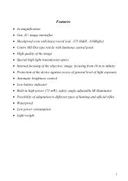
4 XR5 <strong>Image</strong> <strong>Intensifiers</strong>+As a result of sustained and continuing product development, DEP is proud to introduce the latest,innovative XR5 <strong>Image</strong> Intensifier with unprecedented performance for any environment and anycircumstance.The XR5 <strong>Image</strong> Intensifier, successor to the well-known and successful XD-4 <strong>Image</strong>Intensifier, reveals even more details of the night and offers an eXtended Range (XR) capabilitythanks to its new technology.Furthermore, the XR5 <strong>Image</strong> Intensifier enables the user to see even more during a full 24-hourday/night operation. This is done by the use of a fully integrated Auto-Gating unit, which controlsthe image not only during day-night-day transitions but also during dynamic lighting conditionssuch as those experienced, for example, in night operations in urban areas. In practice, thismeans no blooming to hinder your mission but dependable imagery throughout. In addition, thehalo is the smallest on the market.The XR5 <strong>Image</strong> Intensifier from DEP represents the new European standard for Night Visionand is available in a variety of inverting and non-inverting 18 mm formats.The new XR5 is your best choice to maintain your combat effectiveness under allcircumstances.a Delft Instruments company Version 21.09.2004 Page 32
4.1 TECHNICAL SPECIFICATIONS: XR5Resolution Minimal Typical Maximal UNITLimiting resolution 64 70 lp/mmModulation Transfer Function:2.5 lp/mm 93 %7.5 lp/mm 82 %15 lp/mm 67 %25 lp/mm 46 %30 lp/mm 35 %Signal to Noise Minimal Typical Maximal UNITSignal to noise (@108µlx) 25 28Luminance dynamic range Minimal Typical Maximal UNITAuto-Gating and Automatic Brightness Control 1.0E-06 5.0E+04 luxOther Technical Data Minimal Typical Maximal UNITPhosphor: P20*Operational Lifetime 15.000 hrsGain at 2E-05 lux 30.000/π 50.000/π cd/m2/lxMax. Output Brightness 2 17 cd/m2E.B.I. 0.25 µlxLuminous sensitivity at 2850K 700 800 µA/lmRadiant sensitivity at 800nm 65 78 mA/WRadiant sensitivity at 850nm 50 65 mA/WInput voltage 2 3.7 VoltInput current 35 mAOutput uniformity at 2850K 1.8:1 3:01Weight (18mm) 80 95 gramsShock 500 g* also available in P43 phosphora Delft Instruments company Version 21.09.2004 Page 33
5 XD-4 <strong>Image</strong> <strong>Intensifiers</strong>The XD-4 is the top grade of the DEP <strong>Image</strong> <strong>Intensifiers</strong>. With the introduction of the XD-4technology a new European Standard for low light imaging was born providing an unprecedentedperformance in Night Vision applications.The XD-4 <strong>Image</strong> <strong>Intensifiers</strong> perform extremely well in all environmental conditions. Its widespectral sensitivity range makes that a perfect picture is obtained no matter in which area the useris (foliage, on water, snow, desert, rocky and barren land) and what the light conditions are (downto heavily overcast starlight).The XD-4 <strong>Image</strong> <strong>Intensifiers</strong> provide as well a superb image under very dynamic lightconditions.The base for the unique performance of the XD-4 is the used technology by DEP. This hasresulted in greatly improved performance parameters that are crucial for good observation, suchas the Signal-to-Noise Ratio (SNR), the Modulation Transfer Function (MTF) and Resolutionunder all circumstances. Add to this the very long lifetime throughout its complete luminancedynamic range and you will be convinced of its unique performance.The performance parameters of the XD-4 <strong>Image</strong> Intensifier are listed in the table below.Highlights of the XD-4 specification are the typical SNR of 24, the resolution of 64 lp/mm andover and - very important - the high MTF at low and intermediate spatial frequencies. The lattergives the image its sharpness and contrast.It goes without saying that the XD-4 tubes can be supplied in every common mechanicalconstruction including inverting and non-inverting fibre-optic output, which also means that usershave the opportunity to upgrade the performance of existing Night Vision Equipment via a drop-inXD-4 <strong>Image</strong> Intensifier.a Delft Instruments company Version 21.09.2004 Page 34
5.1 TECHNICAL SPECIFICATIONS: XD-4Resolution Minimal Typical Maximal UNITLimiting resolutionType I 55 58 lp/mmType II 60 64 lp/mmModulation Transfer Function:2.5 lp/mm 92 %7.5 lp/mm 80 %15 lp/mm 58 %25 lp/mm 38 %30 lp/mm 30 %Signal to Noise Minimal Typical Maximal UNITSignal to noise (@108µlx) 20 24Other Technical Data Minimal Typical Maximal UNITPhosphor: P20*MTTF (to S/N=12) 15.000 hrsGain at 2.10-5 lx 30.000/π 50.000/π cd/m2/lxMax. Output Brightness 2 17 cd/m2E.B.I. 0.15 0.25 µlxOutput uniformity at 2850K 2:01 3:01Weight(18mm) 80 95 gramsShock 500 gLuminous sensitivity at 2850K 600 700 µA/lmRadiant sensitivity at 800nm 50 60 mA/WRadiant sensitivity at 850nm 40 50 mA/W* also available in P43 phosphora Delft Instruments company Version 21.09.2004 Page 35
6 SHD-3 <strong>Image</strong> <strong>Intensifiers</strong>The SHD-3 type of <strong>Image</strong> Intensifier is an upgrade of the well-known DEP Super Generationtube. The SHD-3 technology combines the very good sensitivity of the Super Generation <strong>Image</strong>Intensifier with superior resolution and MTF (see table on the next page below).These improvements produce a much higher contrast in the image. Like for the XD-4 tube,other strong points of the SHD-3 <strong>Image</strong> Intensifier are that it is sensitive in a wide spectral bandthus providing good contrast in all scene circumstances and that no burning occurs until quitebright light levels are experienced.The SHD-3 <strong>Image</strong> Intensifier is characterised by a guaranteed Signal-to-Noise Ratio (SNR) of18 at 108 µlx and a guaranteed limiting resolution of 45 lp/mm. Of course also here it applies thatthe SHD-3 tube can be supplied in almost every mechanical construction which makes itcompatible with both old and new night vision devices.a Delft Instruments company Version 21.09.2004 Page 36
6.1 TECHNICAL SPECIFICATIONS: SHD-3Resolution Minimal Typical Maximal UNITLimiting resolutionType I 45 48 lp/mmType II 50 54 lp/mmModulation Transfer Function:2.5 lp/mm 86 88 %7.5 lp/mm 66 70 %15 lp/mm 44 50 %25 lp/mm 22 30 %30 lp/mm 18 22 %Signal to Noise Minimal Typical Maximal UNITSignal to noise (@108µlx) 18 20Other Technical Data Minimal Typical Maximal UNITPhosphor: P20*MTTF (to S/N=12) 10.000 hrsGain at 2.10-5 lx 30.000/π 50.000/π cd/m2/lxMax. Output Brightness 2 17 cd/m2E.B.I. 0.15 0.25 µlxOutput uniformity at 2850K 2:01 3:01Weight(18mm) 80 95 gramsShock 500 gLuminous sensitivity at 2850K 500 600 µA/lmRadiant sensitivity at 800nm 43 55 mA/WRadiant sensitivity at 850nm 33 45 mA/W* also available in P43 phosphora Delft Instruments company Version 21.09.2004 Page 37
- INTENTIONALLY LEFT BLANK -a Delft Instruments company Version 21.09.2004 Page 38
PRODUCT LINE:INDUSTRIAL, ANALYTICAL and SCIENTIFIC applicationsa Delft Instruments company Version 21.09.2004 Page 39
7 Intensified CCD (ICCD)7.1 INTRODUCTIONCCD is an abbreviation for Charge-Coupled Device. A CCD is a pixelised silicon lightsensor that converts light into charge within the pixels and transfers the charge packagessequentially to an amplifier reading out the charge packages occurs with cameraelectronics. CCDs are commonly used as image sensors in professional and consumertelevision cameras and camcorders, and as image sensors in digital still cameras.ICCDs are <strong>Image</strong> <strong>Intensifiers</strong> coupled to a CCD bymeans of either relay lens or fibre optics. DEP useshighly efficient fibre optic coupling because of itsexcellent performance. A compatible camera systemshould be used to readout the image. An ICCD cameraconsisting of an ICCD connected to monochromecamera electronics produces a monochrome composite video signal that can be viewed ona monitor. The compact ICCD package makes sure that low light level cameras arelightweight and compact. This can be a vital detail in surveillance and security situations.ICCD cameras are of great help in guarding territories or properties where artificial lightingis not allowed or not available. Other applications include police surveillance, licence plateregistration, highway patrol and the recording of wildlife movies. A fast shutter option canbe supplied, when ICCDs have to operate in strongly varying light conditions e.g. duringday and night.The flexibility in image intensifier design opens possibilities for different applications likeforensic criminal investigation and fire alarm systems. The fire alarm systems are able toa Delft Instruments company Version 21.09.2004 Page 40
operate in full daylight because of the image intensifiers solar-blind photocathodetechnology called SB-200 TM .7.1.1 DESCRIPTION OF BASIC ICCDFor proper imaging at light-levels down to heavily overcast starlight conditions DEP XD-4 TMtype of <strong>Image</strong> <strong>Intensifiers</strong> can be used. The compact XX1700 ICCD consists of a doubleproximity focused XD-4 TM Technology image intensifier directly coupled to a CCD via afibre-optic minifier. The demagnification is adapted to the format of the CCD used.Two basic types exist: A tube de-magnifying from 18 to 11 mm matching to a 2/3 – inch format CCD A tube with a demagnification from 18 to 8 mm for matching to a 1/2 – inch CCD.The designs are very flexible, which means that any CCD of the right format can becoupled to the respective <strong>Image</strong> <strong>Intensifiers</strong>.7.2 PERFORMANCE CHARACTERISTICS OF THE BASIC ICCDThe performance of the ICCD’s is expressed in terms of MTF and resolution, signal-tonoiseratio and lifetime.7.2.1 MTF AND RESOLUTIONA way to determine the sensitivity of sensors is to measure the resolution behaviour as afunction of light level. The resolution at high light-levels is determined by the MTFcontributions of the individual tube components. The resolution plateau lowers when thenumber of intensification stages increases.At lower light-levels image details become obscured by noise which means that now thesignal-to-noise ratio is the important factor for the resolving power. Both higherphotocathode sensitivity and higher gain lead to a higher resolution in this light-level range.a Delft Instruments company Version 21.09.2004 Page 41
7.2.2 SIGNAL-TO-NOISE RATIOAnother method of measuring the performance of image forming systems is based onsignal-to-noise ratio (S/N).Noise in ICCD has three distinct origins:1. dark noise of the image intensifier and CCD2. photon noise which depends on the illumination level detector performance3. structural noise due to unwanted light modulationBackground noise gives rise to a 10 dB dependence for the S/N as a function of inputillumination, photon noise has a 5 dB dependence, whereas for structural noise S/N =constant. A higher gain gives an improved S/N in the photon counting limit. The muchhigher photocathode sensitivity of a XD-4 TMTechnology image intensifier leads to amarkedly improved S/N.7.2.3 LIFETIMEThe expected lifetime for Super Generation, SHD-3 TM and XD-4 TM tubes lies – at roomtemperature – in the range of 15000 hours. The expected lifetime is here defined as thetime after which still 50% of the original sensitivity is left. The lifetime specification is validthroughout the luminance dynamic range provided that at high light levels the automaticbrightness control is active.a Delft Instruments company Version 21.09.2004 Page 42
7.3 INTEGRATED SYSTEMSFor enabling observation during night-time, Black and White CCD Cameras are beingconnected to image intensifiers, either by lens coupling or fibre-optic coupling. DemagnifyingGeneration 2, Super Generation, SHD-3 TM and the highly sensitive XD-4 TMimage intensifiers are available for this purpose. For imaging under very low light-levelconditions, Super Generation, SHD-3 TM or XD-4 TM types should be used.The gating option offers the possibility to use the ICCD camera as well under daylightcircumstances. Auto-gating ICCD’s based on the XR5 TM <strong>Image</strong> <strong>Intensifiers</strong> of DEP delivera perfect image 24 hours a day without need for an external gain management system.Delft Electronic Products BV couples any type of commercial available 1/2-inch and 2/3-inch format or larger CCD to their state-of-the-art 18mm image intensifiers. 1/3-inch formatCCD’s are an option as well.The type of CCD and camera to be used depends on the specific application of thecustomer. After the application has been defined it should be determined whatrequirements of the relevant performance parameters are. With this information and theapplication an ICCD will be defined according to the specification.a Delft Instruments company Version 21.09.2004 Page 43
7.4 INTENSIFIED CCD’S, MODEL XX1700Description:The XX1700 Intensified CCD (ICCD) consists of a DEP 18 mm format <strong>Image</strong> Intensifierfibre-optically coupled to commercially available CCD’s. The fibre-optic coupling is done inhouse. The flexible design enables a perfect match to the application with respect to thetype of DEP <strong>Image</strong> Intensifier used, the type of CCD used (amongst others ½-inch and2/3-inch format) and the installation of extra features like, e.g., gating.Applications:- Surveillance- Industrial Instrumentation- Analytical Instrumentation- Scientific ResearchPhotocathode types90QE 20%8070QE 10%Sensitivity (mA/W)60504030S20(UV)on MgF 2S20(UV)on quartz.S20onHOT S20on quartzSuper S25on glassQE 5%2010Solar-blindon quartzBroadbandon quartz0100 200 300 400 500 600 700 800 900Wavelength (nm)a Delft Instruments company Version 21.09.2004 Page 44
7.4.1 AVAILABLE OPTIONS FOR ICCD- A variety of different photocathodes matched to a wide range of applications, i.e.Super-S25, XD-4 TM , S20(UV), hot S20, broad band and Solar Blind- Different types of phosphor, determined by the application: P20, P43, P46, P47- Gating, from slow to ultra-fast (subnanosecond range)- Various options for the integrated power-supply- High gain dual MCP <strong>Image</strong> <strong>Intensifiers</strong>- Flexibility in CCD-type- ICMOS devicea Delft Instruments company Version 21.09.2004 Page 45
8 Special <strong>Image</strong> <strong>Intensifiers</strong>, Special ICCD’s and Special ICMOS8.1 INTRODUCTIONDEP serves the communities of Analytical Instrumentation, Industrial Instrumentation,Scientific Research and Surveillance with a wide range of special custom made <strong>Image</strong><strong>Intensifiers</strong>, Intensified CCD’s and ICMOS devices, Photon Counters and Low Light-LevelDetectors.8.2 TYPES OF IMAGE INTENSIFIER COMPONENT OPTIONS• Format: 18 mm, 25 mm or 40 mm useful diagonal• Input window: Quartz, Glass, Fibre-optic and MgF 2• Type of photocathode: S20 and S20UV, broadband, S25 and Super-S25, hot S20• Types of phosphor: P20, P43, P46 and P47• Output window: fibre-optic or Glass• Gating: slow gating (faster than 100 ns), fast gating (faster than 5 ns) and ultra fastgating (faster than 300 picoseconds)• Integrated or separate power-supply depending on the exact type, equipped withExternal Gain Control (EGAC) and either with or without Automatic Brightness Control(ABC)• Option: chevron MCP-stack, either 40/40 or 40/80 (dual MCP tube).a Delft Instruments company Version 21.09.2004 Page 46
Figure 10. Photocathode typesFigure 11. Photocathode types (fast gated)a Delft Instruments company Version 21.09.2004 Page 47
Common Phosphor types:Phosphor type Efficiency (photons/e - /effective kV) Decay time down to 1 %P20 35 220 msP43 18 3 msP46* 6 2 µsP47* 6 0.4 µs*) the decay time for these phosphors is measured at 1 µs exposure time.a Delft Instruments company Version 21.09.2004 Page 48
8.3 GATED TUBESFluorescence is the phenomenon that a specimen emits a weak light signal after it isexcited by a light source. Besides amplification to observable levels fluorescence detectionrequires the presence of a fast optical shutter to block the effect of the excitation light. Theease with which the MCP-based <strong>Image</strong> <strong>Intensifiers</strong> of DEP can be gated makes them idealcandidates for fluorescence imaging and fluorescence spectroscopy.The MCP-based <strong>Image</strong> <strong>Intensifiers</strong> of DEP can be gated down to the nanosecond rangeand beyond because of:• an excellent shutter ratio in the range of 1.0E09 through which contrast is wellmaintained down to the minimum gate time.• A short Iris Delay lying in the subnanosecond range if there is a metallic underlayunderneath the photocathode. The Iris Delay is the time difference in opening of thephotocathode between the edge and the centre of the tube.• A big advantage of the DEP <strong>Image</strong> <strong>Intensifiers</strong> is that gating can be done with voltagepulses across the front gap of 240 Volt only. How fast a particular tube can be gated inpractice is determined by its Iris Delay. With respect to the gate speed the DEP tubescan be divided into 3 categories:• Slow gate-able tubes: these tubes without underlay gate faster than 100 ns (18 mmand 25 mm tubes) or 300 ns (40 mm format tubes). DEP produces compatible GateUnits, model number PP0100U.• Fast gate-able tubes: these tubes with underlay gate faster than 5 ns• Ultra fast gate-able tubes: these tubes with a special construction gate faster than 300picoseconds.a Delft Instruments company Version 21.09.2004 Page 49
9 Photon Counters9.1.1 INTRODUCTIONPhoton Counters can detect each photoelectron almost without any noise.This can be realised by a few different techniques. The important ones are:- MCP (Micro Channel Plate) detectors with resistive read-out. This is an ImagingPhoton detector (IPD).- MCP detectors with Phosphor/CCD readout. This is an Imaging Photon Detector aswell.- Hybrid Photo Diode (HPD). The HPD is produced in single-pixel and multi-pixelversions up to 163 - pixels.DEP produces all these types.MCP detectorMulti Pixel HPMTa Delft Instruments company Version 21.09.2004 Page 50
9.1.2 MCP PHOTON COUNTERSMicro Channel Plates (MCP) are often used in image intensifiers to amplify the signal.Figure 12. MCP amplificationThe photon counter version has a stack of two MCP’s which is operated in the saturationmode. This mode has a very high MCP gain and a peaked Pulse Height Distribution(PHD). The quality of the PHD is characterised by:- High gain: G- Small gain spread: G- The depth of the valleyIn figure 13 these numbers are visualised. A high quality MCP photon Counter has a lowG/G and a low valley.Typical characteristics for DEP MCPPhoton counters are:- Gain: minimum up to 10 7 e/e- G/G between 60%and 100%- Valley less than 10% of the peak valueFigure 13. Saturated Pulse Height Distribution for MCP photon countersa Delft Instruments company Version 21.09.2004 Page 51
Typical characteristics for DEP MCP photon counters:- Gain: minimum up to 10 7 e/e.- G/G between 60% and 100%- Valley less then 10% of the peak valueA photon counter is able to record each event. Each event will then be judged by theelectronics: low gain events will be rejected. The low gain tail of the PHD is noise. Thepeaked part represents the real events. By putting the discrimination level in the valley, theoptimal setting for a photon counter is achieved. A low valley characterises a high qualityphoton counter.a Delft Instruments company Version 21.09.2004 Page 52
9.1.3 MCP PHOTON COUNTER WITH CCD READ-OUTAfter the MCP amplification step, the information has to be read out. A conventional way todo this is by first converting the electron-image to a visible image with the aid of aphosphor screen. A CCD + camera can then read the image. Usually a de-magnifying fibreoptic taper is used to match the input diameter of the image intensifier to the CCD format.Figure 14. MCP amplifier with CCD read-outThe timing limitation of the CCD solution is set by the frame rate. The minimum frame is~ 10 milliseconds. So the maximum rate is about 100 Hertz.a Delft Instruments company Version 21.09.2004 Page 53
9.1.4 MCP PHOTON COUNTER WITH RESISTIVE ANODE READ-OUTAnother way of recording of the signal is to use conductive or resistive read-out plates.The latter is the most popular one.The signal is read as follows:Figure 15. Resistive anode intensifierAn amplified event is collected on the anode plate. The charge spreads out to the contactsA, B, C and D. With the aid of charge preamplifiers the signals can be measured.Figure 16. Resistive anode platea Delft Instruments company Version 21.09.2004 Page 54
The contact that is closest to the event will record the highest current.The shape of the anode plate is such that the following algorithm will help to easilydetermine the centre of the event:X( A + B)− ( C + D)=A + B + C + DY( B + C)− ( A + D)=A + B + C + DThe resistive anode intensifier is very fast. The preamplifiers set much of the speed limit.Inside the intensifier the event has duration in the range of nanoseconds.a Delft Instruments company Version 21.09.2004 Page 55
9.1.5 HYBRID PHOTO DIODE (HPD)The Hybrid Photo-Diode (HPD) consists of a PIN diode integrated in a vacuum tube. Likefor <strong>Image</strong> <strong>Intensifiers</strong>, the HPD is equipped with a photocathode in which the photons areconverted into photoelectrons. After acceleration the photoelectrons bombard the diodeand secondary electrons are created inside the diode. By using proper preamp’s ameasurable signal is obtained. Both single pixel and multi-pixel devices are available. TheHPD is an example of a Photon Counter.One diode/single pixelMulti Pixel HPDFigure 17. Pulse Height Distribution of an HPDa Delft Instruments company Version 21.09.2004 Page 56
- INTENTIONALLY LEFT BLANK -a Delft Instruments company Version 21.09.2004 Page 57
10 Specification and mechanical characteristicsUse this summary as a quick reference to select the image intensifier required. You willfind details on the selected tube in the performance sheet hereafter.COMMON NIGHT VISION IMAGE INTENSIFIERSDEP TYPEidentifierPerformanceTypicalResolutionTypicalS/NInputWindowOutputInvertingCompatible withXX2540B XR5 70 28 Glass Yes Aviator Golden Bullet like 10160XX2540D XR5 TM 70 28 Glass Yes MX-10160, F9800, small ANVISXX2550F XR5 TM 70 28 Glass No MX-10130, F9810, PVS-7 Uni.XX2040CX XD-4 TM 64 24 Glass Yes Aviator Golden Bullet like 10160XX2040AU XD-4 TM 64 24 Glass Yes MX-10160, F9800, small ANVISXX2040AR XD-4 TM 64 22 Glass Yes MX-10160, F9800, small ANVISXX2050BL XD-4 TM 64 24 Glass No MX-10130, F9810, PVS-7 Uni.XX2040AN XD-4 TM 64 22 Glass Yes M-868, fat ANVIS, flying leadsXX2040C XD-4 TM 58 24 Glass Yes MX-10160, F9800, small ANVISXX2050R XD-4 TM 58 24 Glass No MX-10130, F9810, PVS-7 Uni.XX1940AM SHD-3 TM 48 20 Glass Yes MX-10160, F9800, small ANVISXX1950DK SHD-3 TM 48 21 Glass No MX-10130, F9810, PVS-7 Uni.a Delft Instruments company Version 21.09.2004 Page 58
COMMON Industrial, Analytical and Scientific IMAGE INTENSIFIERSDEP TYPEidentifierPerformanceTypicalResolutionTypicalS/NInputWindowOutputInvertingXX1700DN XD-4 TM 60 22 Glass - -PP0340AT Gen II 34 - Quartz No -PP0400G Gen II 30 - Fiber No -XX1440ES Gen II 40 - Quartz Yes -XX1450KT Gen II 45 - Quartz No -XX1450XK Gen II 45 - Quartz No -XX1450TJ Gen II 48 - Fiber No -XX2050AH XD-4 TM 58 20 Glass No -XX2050F XD-4 TM 58 24 Glass No -Compatible witha Delft Instruments company Version 21.09.2004 Page 59
<strong>Image</strong> Intensifier Tubes Performance Level : XR5 TMDEP Tube Type : XX2540BFormat: 18 mmTube Name: Small ANVIS (Golden Bullet)Compatible: MX-10160, F9800Applications : to be used in Aviator Goggles.General Tube information : Input WindowGlassOutput Window Inverting Fibre OpticMagnification 1Electrical controls Automatic Brightness Control (ABC)Bright Source Protection (BSP)Auto-GatingEMCMIL-STD-461, MIL-STD-462Electronic connections gold plated contactsWeight80 gramsUseful Cathode Diameter 17.5 mmPhosphorP43Tube CharacteristicsTypical Min. Max. UnitOptical Limiting Resolution 70 64 lp/mmModulation Transfer Function2.5 lp/mm 93 %7.5 lp/mm 82 %15 lp/mm 67 %25 lp/mm 46 %30 lp/mm 35 %Signal to noise (@108 lx) 26 23Gain at 2x10 -6 fc 45.000 30.000 50.000 fL/fcLife time 15.000 hrsMax. Output Brightness (MOB) 6 4 8 cd/m 2EBI 0.15 0.25 lxOutput Uniformity at 2850K 1.8:1 3:1Luminous Sensitivity at 2850K 800Radiant Sensitivity at 800 nm 78 mA/W850 nm 65 mA/WShock resistance 700g m/s 2Electrical Operating Voltage 2.7 2.0 3.7 VInput Current 35 mAEnvironment Operating temperature (8 hrs) -45 +52 ˚CStorage temperature (8 hrs) -51 +65 ˚CLuminance dynamic range 1x10 -6 5x10 4 luxa Delft Instruments company
<strong>Image</strong> Intensifier Tubes Performance Level : XR5 TMDEP Tube Type : XX2540DFormatTube NameCompatibleApplications: 18 mm: Small ANVIS: MX-10160, F9800: to be used in Goggles, Monoculars and other systems.General Tube information : Input WindowGlassOutput Window Inverting Fibre OpticMagnification 1Electrical controls Automatic Brightness Control (ABC)Bright Source Protection (BSP)Auto-GatingEMCproofElectronic connections gold plated contactsWeight80 gramsUseful Cathode Diameter 17.5 mmPhosphorP20Tube CharacteristicsTypical Min. Max. UnitOptical Limiting Resolution 70 64 lp/mmModulation Transfer Function2.5 lp/mm 93 %7.5 lp/mm 82 %15 lp/mm 67 %25 lp/mm 46 %30 lp/mm 35 %Signal to noise (@108 lx) 28 25Gain at 2x10 -6 fc 45.000 30.000 50.000 fL/fcLife time 15.000 hrsMax. Output Brightness (MOB) 6 4 8 cd/m 2EBI 0.15 0.25 lxOutput Uniformity at 2850K 1.8:1 3:1Luminous Sensitivity at 2850K 800Radiant Sensitivity at 800 nm 78 mA/W850 nm 65 mA/WShock resistance 700g m/s 2Electrical Operating Voltage 2.7 2.0 3.7 VInput Current 35 mAEnvironment Operating temperature (8 hrs) -45 +52 ˚CStorage temperature (8 hrs) -51 +65 ˚CLuminance dynamic range 1x10 -6 5x10 4 luxa Delft Instruments company
<strong>Image</strong> Intensifier Tubes Performance Level : XR5 TMDEP Tube Type : XX2550FFormat: 18 mmTube Name: PVS-7 UniversalCompatible: MX-10130, F9810Applications : to be used in PVS-7A/B/D Night Vision Goggles, and other systems.General Tube information : Input WindowGlassOutput Window Non-Inverting Fibre OpticMagnification 1Electrical controls Automatic Brightness Control (ABC)Bright Source Protection (BSP)Auto-GatingEMCproofElectronic connections contactsWeight98 gramsUseful Cathode Diameter 17.5 mmPhosphorP20Tube CharacteristicsTypical Min. Max. UnitOptical Limiting Resolution 70 64 lp/mmModulation Transfer Function2.5 lp/mm 93 %7.5 lp/mm 82 %15 lp/mm 67 %25 lp/mm 46 %30 lp/mm 35 %Signal to noise (@108 lx) 28 25Gain at 2x10 -6 fc 45.000 30.000 50.000 fL/fcLife time 15.000 hrsMax. Output Brightness (MOB) 6 4 8 cd/m 2EBI 0.15 0.25 lxOutput Uniformity at 2850K 1.8:1 3:1Luminous Sensitivity at 2850K 800Radiant Sensitivity at 800 nm 78 mA/W850 nm 65 mA/WShock resistance 700g m/s 2Electrical Operating Voltage 2.7 2.0 3.7 VInput Current 35 mAEnvironment Operating temperature (8 hrs) -45 +52 ˚CStorage temperature (8 hrs) -51 +65 ˚CLuminance dynamic range 1x10 -6 5x10 4 luxa Delft Instruments company
<strong>Image</strong> Intensifier Tubes Performance Level : XD-4 TMDEP Tube Type : XX2040CXFormatTube NameCompatibleApplications: 18 mm: Small ANVIS (Golden Bullet): MX-10160, F9800: to be used in Aviator Goggles.General Tube information : Input WindowGlassOutput Window Inverting Fibre OpticMagnification 1Electrical controls Automatic Brightness Control (ABC)Bright Source Protection (BSP)EMCMIL-STD-461, MIL-STD-462Electronic connections gold plated contactsWeight80 gramsUseful Cathode Diameter 17.5 mmPhosphorP43Tube CharacteristicsTypical Min. Max. UnitOptical Limiting Resolution 64 60 lp/mmModulation Transfer Function2.5 lp/mm 92 88 %7.5 lp/mm 80 72 %15 lp/mm 64 54 %25 lp/mm 45 40 %30 lp/mm 35 30 %Signal to noise (@108 lx) 24 20Gain at 2x10 -6 fc 32.000 28.000 38.000 fL/fcLife time 10.000 hrsMax. Output Brightness (MOB) 6 4 8 cd/m 2EBI 0.15 0.25 lxOutput Uniformity at 2850K 2:1 3:1Luminous Sensitivity at 2850K 700 600Radiant Sensitivity at 800 nm 60 50 mA/W850 nm 50 40 mA/WShock resistance 700g 500g m/s 2Electrical Operating Voltage 2.7 2.0 3.7 VInput Current 22 16 26 mAEnvironment Operating temperature -45 +52 ˚CStorage temperature -52 +65 ˚Ca Delft Instruments company
<strong>Image</strong> Intensifier Tubes Performance Level : XD-4 TMDEP Tube Type : XX2040AUFormatTube NameCompatibleApplications: 18 mm: Small ANVIS: MX-10160, F9800: to be used in Goggles, Monoculars, and other systems.General Tube information : Input WindowGlassOutput Window Inverting Fibre OpticMagnification 1Electrical controls Automatic Brightness Control (ABC)Bright Source Protection (BSP)EMCproofElectronic connections gold plated contactsWeight80 gramsUseful Cathode Diameter 17.5 mmPhosphorP20Tube CharacteristicsTypical Min. Max. UnitOptical Limiting Resolution 64 60 lp/mmModulation Transfer Function2.5 lp/mm 92 90 %7.5 lp/mm 80 72 %15 lp/mm 64 54 %25 lp/mm 45 40 %30 lp/mm 35 30 %Signal to noise (@108 lx) 24 20Gain at 2x10 -6 fc 32.000 28.000 38.000 fL/fcLife time 15.000 hrsMax. Output Brightness (MOB) 6 4 8 cd/m 2EBI 0.15 0.25 lxOutput Uniformity at 2850K 2:1 3:1Luminous Sensitivity at 2850K 700 600Radiant Sensitivity at 800 nm 60 50 mA/W850 nm 50 40 mA/WShock resistance 700g 500g m/s 2Electrical Operating Voltage 2.7 2.0 3.7 VInput Current 22 16 26 mAEnvironment Operating temperature -45 +52 ˚CStorage temperature -51 +65 ˚Ca Delft Instruments company
<strong>Image</strong> Intensifier Tubes Performance Level : XD-4 TMDEP Tube Type : XX2040ARFormatTube NameCompatibleApplications: 18 mm: Small ANVIS: MX-10160, F9800: to be used in Aviator Goggles, and other systems.General Tube information : Input WindowGlassOutput Window Inverting Fibre OpticMagnification 1Electrical controls Automatic Brightness Control (ABC)Bright Source Protection (BSP)EMCproofElectronic connections contactsWeight80 gramsUseful Cathode Diameter 17.5 mmPhosphorP43Tube CharacteristicsTypical Min. Max. UnitOptical Limiting Resolution 64 60 lp/mmModulation Transfer Function2.5 lp/mm 92 90 %7.5 lp/mm 80 76 %15 lp/mm 65 60 %25 lp/mm 45 40 %30 lp/mm 35 30 %Signal to noise (@108 lx) 22 20Gain at 2x10 -6 fc 39.200 32.000 45.000 fL/fcLife time 10.000 hrsMax. Output Brightness (MOB) 6 4 8 cd/m 2EBI 0.15 0.25 lxOutput Uniformity at 2850K 2:1 3:1Luminous Sensitivity at 2850K 700 600Radiant Sensitivity at 800 nm 60 50 mA/W850 nm 50 40 mA/WShock resistance 700g 500g m/s 2Electrical Operating Voltage 2.7 2.0 3.8 VInput Current 26 mAEnvironment Operating temperature -45 +52 ˚CStorage temperature -51 +65 ˚Ca Delft Instruments company
<strong>Image</strong> Intensifier Tubes Performance Level : XD-4 TMDEP Tube Type : XX2050BLFormatTube NameCompatibleApplications: 18 mm: PVS-7 Universal: MX-10130, F9810: to be used in PVS-7A/B/D Night Vision Goggles and other systems.General Tube information : Input WindowGlassOutput Window Non-Inverting Fibre OpticMagnification 1Electrical controls Automatic Brightness Control (ABC)Bright Source Protection (BSP)EMCproofElectronic connections contactsWeight98 gramsUseful Cathode Diameter 17.5 mmPhosphorP20Tube CharacteristicsTypical Min. Max. UnitOptical Limiting Resolution 64 60 lp/mmModulation Transfer Function2.5 lp/mm 92 %7.5 lp/mm 80 %15 lp/mm 58 %25 lp/mm 38 %30 lp/mm 30 %Signal to noise (@108 lx) 24 20Gain at 2x10 -6 fc 35.000 30.000 40.000 fL/fcLife time 10.000 hrsMax. Output Brightness (MOB) 10.2 6.8 13.6 cd/m 2EBI 0.15 0.25 lxOutput Uniformity at 2850K 2:1 3:1Luminous Sensitivity at 2850K 700 600Radiant Sensitivity at 800 nm 60 50 mA/W850 nm 50 40 mA/WShock resistance 700g 500g m/s 2Electrical Operating Voltage 2.7 2.0 3.8 VInput Current 22 mAEnvironment Operating temperature -45 +52 ˚CStorage temperature -51 +65 ˚Ca Delft Instruments company
<strong>Image</strong> Intensifier Tubes Performance Level : XD-4 TMDEP Tube Type : XX2040ANFormatTube NameCompatibleApplications: 18 mm: fat ANVIS: MX-868: to be used in Goggles, and other systems.General Tube information : Input WindowGlassOutput Window Inverting Fibre OpticMagnification 1Electrical controls Automatic Brightness Control (ABC)Bright Source Protection (BSP)EMCproofElectronic connections flying leadsWeight98 gramsUseful Cathode Diameter 17.5 mmPhosphorP20Tube CharacteristicsTypical Min. Max. UnitOptical Limiting Resolution 58 55 lp/mmModulation Transfer Function2.5 lp/mm 92 88 %7.5 lp/mm 80 72 %15 lp/mm 58 54 %25 lp/mm 38 35 %30 lp/mm 30 25 %Signal to noise (@108 lx) 22 20Gain at 2x10 -6 fc 28.000 31.000 37.500 fL/fcLife time 10.000 hrsMax. Output Brightness (MOB) 4.5 3 6 cd/m 2EBI 0.15 0.25 lxOutput Uniformity at 2850K 2:1 3:1Luminous Sensitivity at 2850K 700 600Radiant Sensitivity at 800 nm 60 50 mA/W850 nm 50 40 mA/WShock resistance 700g 500g m/s 2Electrical Operating Voltage 2.7 2.0 3.8 VInput Current 12 24 mAEnvironment Operating temperature -45 +52 ˚CStorage temperature -52 +65 ˚Ca Delft Instruments company
<strong>Image</strong> Intensifier Tubes Performance Level : XD-4 TMDEP Tube Type : XX2040CFormatTube NameCompatibleApplications: 18 mm: Small ANVIS: MX-10160, F9800: to be used in Goggles, Monoculars, and other systems.General Tube information : Input WindowGlassOutput Window Inverting Fibre OpticMagnification 1Electrical controls Automatic Brightness Control (ABC)Bright Source Protection (BSP)EMCproofElectronic connections contactsWeight80 gramsUseful Cathode Diameter 17.5 mmPhosphorP20Tube CharacteristicsTypical Min. Max. UnitOptical Limiting Resolution 58 55 lp/mmModulation Transfer Function2.5 lp/mm 92 86 %7.5 lp/mm 80 72 %15 lp/mm 58 54 %25 lp/mm 38 35 %30 lp/mm 30 25 %Signal to noise (@108 lx) 24 20Gain at 2x10 -6 fc 28.500 25.000 32.000 fL/fcLife time 15.000 hrsMax. Output Brightness (MOB) 6 4 8 cd/m 2EBI 0.15 0.25 lxOutput Uniformity at 2850K 2:1 3:1Luminous Sensitivity at 2850K 700 600Radiant Sensitivity at 800 nm 60 50 mA/W850 nm 50 40 mA/WShock resistance 700 500g m/s 2Electrical Operating Voltage 2.7 2.0 3.8 VInput Current 22 16 26 mAEnvironment Operating temperature -45 +52 ˚CStorage temperature -51 +65 ˚Ca Delft Instruments company
<strong>Image</strong> Intensifier Tubes Performance Level : XD-4 TMDEP Tube Type : XX2050RFormatTube NameCompatibleApplications: 18 mm: PVS-7 Universal: MX-10130: to be used in PVS-7A/B/D Night Vision Goggles, and other systems.General Tube information : Input WindowGlassOutput Window Non-Inverting Fibre OpticMagnification 1Electrical controls Automatic Brightness Control (ABC)Bright Source Protection (BSP)EMCproofElectronic connections contactsWeight98 gramsUseful Cathode Diameter 17.5 mmPhosphorP20Tube CharacteristicsTypical Min. Max. UnitOptical Limiting Resolution 58 55 lp/mmModulation Transfer Function2.5 lp/mm 92 90 %7.5 lp/mm 80 72 %15 lp/mm 58 54 %Signal to noise (@108 lx) 24 20Gain at 2x10 -6 fc 35.000 30.000 40.000 fL/fcLife time 10.000 hrsMax. Output Brightness (MOB) 10.2 6.8 13.6 cd/m 2EBI 0.15 0.25 lxOutput Uniformity at 2850K 2:1 3:1Luminous Sensitivity at 2850K 700 600Radiant Sensitivity at 800 nm 60 50 mA/W850 nm 50 40 mA/WShock resistance 700g 500g m/s 2Electrical Operating Voltage 2.7 2.0 3.8 VInput Current 22 mAEnvironment Operating temperature -45 +52 ˚CStorage temperature -51 +65 ˚Ca Delft Instruments company
<strong>Image</strong> Intensifier Tubes Performance Level : SHD-3 TMDEP Tube Type : XX1940AMFormatTube NameCompatibleApplications: 18 mm: Small ANVIS: MX-10160: to be used in Goggles, Monoculars and other systems.General Tube information : Input WindowGlassOutput Window Inverting Fibre OpticMagnification 1Electrical controls Automatic Brightness Control (ABC)Bright Source Protection (BSP)EMCproofElectronic connections contactsWeight80 gramsUseful Cathode Diameter 17.5 mmPhosphorP20Tube CharacteristicsTypical Min. Max. UnitOptical Limiting Resolution 48 45 lp/mmModulation Transfer Function2.5 lp/mm 88 86 %7.5 lp/mm 70 66 %15 lp/mm 50 44 %25 lp/mm 30 22 %30 lp/mm 22 18 %Signal to noise (@108 lx) 21 18Gain at 2x10 -6 fc 23.250 18.500 28.000 fL/fcLife time 10.000 hrsMax. Output Brightness (MOB) 3 2 4 cd/m 2EBI 0.15 0.25 lxOutput Uniformity at 2850K 2:1 3:1Luminous Sensitivity at 2850K 600 500Radiant Sensitivity at 800 nm 55 43 mA/W850 nm 45 33 mA/WShock resistance 700g 500g m/s 2Electrical Operating Voltage 2.7 2.0 3.4 VInput Current 16 26 mAEnvironment Operating temperature -30 +52 ˚CStorage temperature -35 +65 ˚Ca Delft Instruments company
<strong>Image</strong> Intensifier Tubes Performance Level : SHD-3 TMDEP Tube Type : XX1950DKFormatTube NameCompatibleApplications: 18 mm: PVS-7 Universal: MX-10130: to be used in PVS-7A/B/D Night Vision Goggles and other systems.General Tube information : Input WindowGlassOutput Window Non-Inverting Fibre OpticMagnification 1Electrical controls Automatic Brightness Control (ABC)Bright Source Protection (BSP)EMCproofElectronic connections contactsWeight98 gramsUseful Cathode Diameter 17.5 mmPhosphorP20Tube CharacteristicsTypical Min. Max. UnitOptical Limiting Resolution 48 45 lp/mmModulation Transfer Function2.5 lp/mm 90 88 %7.5 lp/mm 76 70 %15 lp/mm 54 50 %25 lp/mm 35 30 %Signal to noise (@108 lx) 21 18Gain at 2x10 -6 fc 33.000 28.200 37.700 fL/fcLife time 10.000 hrsMax. Output Brightness (MOB) 6 4 8 cd/m 2EBI 0.15 0.25 lxOutput Uniformity at 2850K 2:1 3:1Luminous Sensitivity at 2850K 600 500Radiant Sensitivity at 800 nm 50 45 mA/W850 nm 40 35 mA/WShock resistance 700g 500g m/s 2Electrical Operating Voltage 2.7 2.0 3.8 VInput Current 24 mAEnvironment Operating temperature -45 +52 ˚CStorage temperature -51 +65 ˚Ca Delft Instruments company
<strong>Image</strong> Intensifier Tubes Performance Level : XD-4 TMDEP Tube Type : XX1700DNFormatTube NameFormatApplications: 18 mm: Sony ICX423: 2/3-inch: low light level applications, surveillance.General Tube information : Input WindowEMCElectrical connectionsUseful Cathode DiameterPhosphorTapered Fibre opticTube CharacteristicsGlassproofflying leads17.5 mmP20Typical Min. Max.0.63 0.61 0.65Typical Min. Max. UnitOptical Limiting Resolution 60 55 lp/mmSignal to noise (@108 lx) 22 20Luminance gain* (max. gain at 0V) 22000 19000 fL/fcLife time 10.000 hrsMax. Output Brightness (MOB) 3 2 4 cd/m 2EBI 0.15 0.25 lxLuminous Sensitivity at 2850K 700 600 a/lmRadiant Sensitivity at 800 nm 55 50 mA/W850 nm 45 40 mA/WEnvironment Operating temperature +20 -20 +50 ˚CStorage temperature -30 +60 ˚C*External gain control (EGAC)The gain can be adjusted by a voltage between 0 and 10 V from its pre-set maximum value at 0 V toa nihil gain at 10 V.Low-Light Level <strong>Image</strong> SensorMinimum Nominal UnitResolution 520 540 TV-lines/ Picture Height<strong>Image</strong> SensorType:Sony ICX423 high resolution interline CCD compatiblewith CCIR B/W TV-system.<strong>Image</strong> area (2/3"): 8.8 mm (hor) x 6.6 mm (vert)The <strong>Image</strong> Sensor is directly coupled to the tapered fibre-optic.a Delft Instruments company
<strong>Image</strong> Intensifier Tubes Performance Level : GEN IIDEP Tube Type : PP0340ATFormatApplications: 25 mm: Analytical/Industrial InstrumentationGeneral Tube information : Input WindowQuartsOutput windowNon inverting Fibre OpticMagnification 1Electrical controls Gating and external gain controlElectrical connections WiresUseful Cathode Diameter 24.5 mmPhosphorP43Tube CharacteristicsTypical Min. Max. UnitOptical Limiting Resolution 35 28 lp/mmGain at V c = 0V 4.000 3.180 cd/m 2 /lxEBI 0.1 0.2 lxRadiant Sensitivity at 270 nm 55 50 mA/W440 nm 45 40 mA/WNon Uniformity 40 %ElectricalGateable down to 100nsIris delay 30 nsSupply voltage 4 5 6 VDCEGAC control voltage (Vc) 0 10 VDCEnvironment Operating temperature +20 -30 +60 ˚CStorage temperature +20 -30 +50 ˚CThe luminance gain of the image intensifier is adjustable by means of an external controlvoltage from its pre-set maximum value at V c = 0 V to a nihil gain at V c = 10 V.A spectral photocathode sensitivity curve, vignetting curves and an EGAC curve shall beprovided with the test data.a Delft Instruments company
<strong>Image</strong> Intensifier Tubes Performance Level : GEN IIDEP Tube Type : PP0400GFormatApplications: 40 mm: Industrial InstrumentationGeneral Tube information : Input WindowFibre OpticOutput windowFibre OpticMagnification 1Electricalc connections WiresUseful Cathode Diameter 40 mmPhosphorP43Tube CharacteristicsTypical Min. Max. UnitOptical Limiting Resolution 30 28 lp/mmGain 4000 cd/m 2 /lxEBI 0.02 0.05 lxRadiant Sensitivity at 440 nm 45 40 mA/W480 nm 45 40 mA/WUniformity within quality area 40 %ElectricalGateable down to 1sSupply voltage 4 5 6 VDCEGAC control voltage (Vc) 0 10 VDCEnvironment Operating temperature +20 -20 +50 ˚CStorage temperature -20 +50 ˚COperating conditions:Name Min. Nom. Max. Unit RemarksAnode voltage V A5400 5700 6000 VDC ref. to V MCP-OUTMCP output voltage V MCP-OUT* * +VDC ref. to V MCP-INMCP input voltage V MCP-IN0 -VDC groundedCathode voltage (on) V C-ON160 200 240 -VDC ref. to V MCP-INCathode voltage (off) V C-OFF30 40 240 VDC ref. to V MCP-INa Delft Instruments company
<strong>Image</strong> Intensifier Tubes Performance Level : XD-4 TMDEP Tube Type : XX1440ESFormatTube NameApplications: 18 mm: small ANVIS: Industrial InstrumentationGeneral Tube information : Input WindowQuartzOutput Window Inverting Fibre OpticMagnification 1Electrical controls Automatic Brightness Control (ABC)Bright Source Protection (BSP)EMCproofElectrical connections contactsWeight80 gramsUseful Cathode Diameter 17.5 mmPhosphorP43Tube CharacteristicsTypical Min. Max. UnitOptical Limiting Resolution 40 36 lp/mmGain at 2x10 -6 fc 6.000 5.000 8.000 cd/m 2Life time 10.000 hrsMax. Output Brightness (MOB) 6 4 8 cd/m 2EBI 0.15 0.25 lxOutput Uniformity at 2850K 3:1Radiant Sensitivity at 270 nm 50 40 mA/W400 nm 60 50 mA/WElectrical Operating Voltage 2.7 2.0 3.4 VEnvironment Operating temperature +20 -30 +60 ˚CStorage temperature +20 -30 +52 ˚Ca Delft Instruments company
<strong>Image</strong> Intensifier Tubes Performance Level : GEN IIDEP Tube Type : XX1450KTFormatApplications: 18 mm: Analytical/Industrial InstrumentationGeneral Tube information : Input WindowQuartzOutput windowFibre OpticMagnification 1Electrical controls Automatic Brightness Control (ABC)Bright Source Protection (BSP)Electrical connections WiresUseful Cathode Diameter 17.5 mmPhosphorP43Tube CharacteristicsTypical Min. Max. UnitOptical Limiting Resolution 45 40 lp/mmMax. output Brightness (MOB) 3 2 4 cd/m 2Luminance gain 4000 3180 cd/m 2 /lxEBI 0.01 0.02 lxRadiant Sensitivity at 440 nm 60 50 mA/W480 nm 50 45 mA/WNon Uniformity 50 %ElectricalGateable down to 100nsOperating voltage 2.7 2 3.4 VDCEnvironment Operating temperature +20 -30 +50 ˚CAmbient temperature -30 +20 +45 ˚CThe luminance gain of the image intensifier is adjustable by means of an external control voltagefrom its preset maximum value (typ. 4000 Cd/m ² /lx) at V c =0 V down to a value which is at least afactor of 100 lower at V c =10 V.a Delft Instruments company
<strong>Image</strong> Intensifier Tubes Performance Level : GEN IIDEP Tube Type : XX1450XKFormatApplications: 18 mm: Analitical InstrumentationGeneral Tube information : Input WindowQuartzOutput windowFibre OpticMagnification 1Electrical controls External Gain Control (EGAC)Electrical connections WiresUseful Cathode Diameter 17.5 mmPhosphorP43Tube CharacteristicsTypical Min. Max. UnitOptical Limiting Resolution 45 40 lp/mmLuminance gain 3.180 cd/m 2 /lxEBI 0.15 0.25 lxPhotcathode sensitivity:wite light 380800 nm 33 mA/W850 nm 25 mA/WElectricalGateable down to 5nsOperating voltage 2.7 2 3.4 VDCEnvironment Operating temperature +20 -30 +50 ˚CAmbient temperature -30 +20 +50 °CThe luminance gain of the image intensifier is adjustable by means of an external control voltagefrom its pre-set maximum value (typ. 4000 cd/m 2 /lx) at V c =0 V down to a value which is at least afactor of 100 lower at V c =10 V.a Delft Instruments company
<strong>Image</strong> Intensifier Tubes Performance Level : GEN IIDEP Tube Type : XX1450TJFormat: 18 mmTube Name :Format :Applications :General Tube information : Input WindowQuartsOutput windowFibre OpticMagnification 1Electrical connections WiresUseful Cathode Diameter 17.5 mmPhosphorP43Tube CharacteristicsTypical Min. Max. UnitOptical Limiting Resolution 50 45 lp/mmLuminance gain 15000 fL/fcCathode sensitivity :Q.E. at 270 nm 11 %Q.E. at 800 nm 1 %Q.E. at 850 nm 0.2 %Peak Q.E. 14 12 %Uniformity (within active area) 10 %EBI 0.1 0.2 lxElectricalGateable down to 5nsOperating voltage 2.7 2 3.4 VDCStripcurrent 13 AIris delay 1.6 nsEnvironment Operating temperature +20 ˚COperating voltages:Name Unit Maximal Nominal RemarksAnode voltage V A VDC 0 groundedMCP output voltage V MCP-OUT -VDC 6000 ref.to anodeMCP input voltage V MCP-IN -VDC * * ref.toV MCP-OUTCath. voltage (on) V C-ON -VDC 200 ref. to V MCP-INCath. voltage (off) V C-OFF +VDC 40 ref. to V MCP-IN* The value that matches the mentioned gain and the maximum value will be indicated on the testsheet.a Delft Instruments company
<strong>Image</strong> Intensifier Tubes Performance Level : XD-4 TMDEP Tube Type : XX2050AHFormatTube Name: 18 mm: fat AnvisGeneral Tube information : Input WindowGlassOutput Window Non-Inverting Fibre OpticMagnification 1Electrical controls Automatic Brightness Control (ABC)Bright Source Protection (BSP)External gain control.EMCproofElectronic connections contactsWeight98 gramsUseful Cathode Diameter 17.5 mmPhosphorP20Tube CharacteristicsTypical Min. Max. UnitOptical Limiting Resolution 58 55 lp/mmModulation Transfer Function2.5 lp/mm 92 %7.5 lp/mm 80 %15 lp/mm 58 %25 lp/mm 38 %30 lp/mm 30 %Signal to noise 20 17Gain at 2x10 -6 fc 21.980 fL/fcMax. Output Brightness (MOB) 12.5 10 13.6 cd/m 2EBI 0.15 0.25 lxLuminous Sensitivity at 2850K 700 600Radiant Sensitivity at 800 nm 60 50 mA/W850 nm 50 40 mA/WElectrical Operating Voltage 2.7 2.0 3.8 VInput Current 22 mAEnvironment Operating temperature -45 +52 ˚CStorage temperature -51 +65 ˚CThe luminance gain of the image intensifier is adjustable by means of an external control voltagefrom its pre-set maximum value (typ. 7500 cd/m 2 /lx) at V c =0 V down to a value which is at least afactor of 100 lower at V c =10 V.a Delft Instruments company
<strong>Image</strong> Intensifier Tubes Performance Level : XD-4 TMDEP Tube Type : XX2050FFormatTube Name: 18 mm: fat ANVISGeneral Tube information : Input WindowGlassOutput Window Non-Inverting Fibre OpticMagnification 1Electrical controls Automatic Brightness Control (ABC),Bright Source Protection (BSP),Gating and External gain control.EMCproofElectronic connections flyng leadsWeight98 gramsUseful Cathode Diameter 17.5 mmPhosphorP20Tube CharacteristicsTypical Min. Max. UnitOptical Limiting Resolution 58 55 lp/mmModulation Transfer Function2.5 lp/mm 92 %7.5 lp/mm 80 %15 lp/mm 58 %25 lp/mm 38 %30 lp/mm 30 %Signal to noise (@108 lx) 24 20Gain at 2x10 -6 fc 30.000 40.000 fL/fcLife time 15.000 hrsMax. Output Brightness (MOB) 3 2 4 cd/m 2EBI 0.15 0.25 lxOutput Uniformity at 2850K 2:1 3:1Luminous Sensitivity at 2850K 700 600Radiant Sensitivity at 800 nm 60 50 mA/W850 nm 50 40 mA/WElectrical Operating Voltage 2.7 2.0 3.8 VInput Current 22 mAGateble down to 10 100 nsEnvironment Operating temperature -45 +52 ˚CStorage temperature -51 +65 ˚CThe luminance gain of the image intensifier is adjustable by means of an external controlvoltage from its preset maximum value (typ. 10.000 cd/m 2 /lx) at V c =0 V down to a value which isat least a factor of 100 lower at V c =10 V.a Delft Instruments company