
Create successful ePaper yourself
Turn your PDF publications into a flip-book with our unique Google optimized e-Paper software.
<strong>Topview</strong> <strong>5750</strong> <strong>SMD</strong> <strong>LED</strong><strong>IWS</strong>-<strong>506</strong>-<strong>RGB</strong>-<strong>K3</strong>5.1 Luminous intensity Rank( mcd, IF = 20mA )RANK RED GREEN BLUEJ 100 - 150K 150 - 300 150 - 300L 300 - 500 300 - 500M 500 - 700 500 - 700N 700 - 900P 900 – 1100Q 1100 - 13005.2 Dominant Wavelength Combination Rank( nm, IF = 20mA )RANK RED GREEN BLUEA 618 - 635 520 – 535 455 - 4755.3 Forward Voltage Rank ( V, IF = 20mA )RANK RED GREEN BLUEa 1.8 - 2.6 3.0 – 3.5 3.0 – 3.5b 3.5 – 4.0 3.5 – 4.0<strong>IWS</strong> – <strong>506</strong>-<strong>RGB</strong>-<strong>K3</strong> Version of 2.0 PAGE : ‹#› / 13
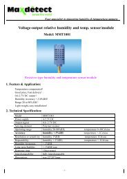
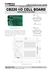
Relative Intensity(%)Forward Current(mA)Relitive Luminous IntensityRelative Luminous Intensity(%)DC Forward Current(mA)<strong>Topview</strong> <strong>5750</strong> <strong>SMD</strong> <strong>LED</strong><strong>IWS</strong>-<strong>506</strong>-<strong>RGB</strong>-<strong>K3</strong>6.2 GreenForward Current vs.Forward Voltage100Forward Current vs.Ambient Temperature403010201012.0 2.5 3.0 3.5 4.0 4.5Forward Voltage(V)Relative Luminous Intensity vs.Ambient Temperature1000 20 40 60 80 100Ambient Temperature( ℃ )Relative Luminous Intensity vs.Forward Current1501001500.10 20 40 60 80Ambient Temperature(℃) ℃Relative Intensity vs. Wavelength100806040200400 500 600 700 800Wavelength(nm)Relative Luminoussity(a.u)Radiation Diagram10.509000 10 20 30Forward Current(mA)Temp=25℃IF=20mA0 109060 30 0 0.51Radiation Angle203040<strong>506</strong>07080<strong>IWS</strong> – <strong>506</strong>-<strong>RGB</strong>-<strong>K3</strong> Version of 2.0 PAGE : ‹#› / 13
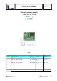
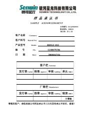
Relative Intensity(%)Forward Current(mA)Relitive Luminous IntensityRelative Luminous Intensity(%)DC Forward Current(mA)<strong>Topview</strong> <strong>5750</strong> <strong>SMD</strong> <strong>LED</strong><strong>IWS</strong>-<strong>506</strong>-<strong>RGB</strong>-<strong>K3</strong>6.3 BlueForward Current vs.Forward Voltage100Forward Current vs.Ambient Temperature403010201012.0 2.5 3.0 3.5 4.0 4.5Forward Voltage(V)Relative Luminous Intensity vs.Ambient Temperature1000 20 40 60 80 100Ambient Temperature( ℃ )Relative Luminous Intensity vs.Forward Current1501001500.10 20 40 60 80Ambient Temperature(℃) ℃Relative Intensity vs. Wavelength100806040200300 400 500 600 700 800Peak Wavelength(nm)Relative Luminoussity(a.u)Radiation Diagram10.509000 10 20 30Forward Current(mA)Temp=25℃IF=20mA0 109060 30 0 0.51Radiation Angle203040<strong>506</strong>07080<strong>IWS</strong> – <strong>506</strong>-<strong>RGB</strong>-<strong>K3</strong> Version of 2.0 PAGE : ‹#› / 13
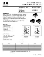
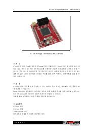
<strong>Topview</strong> <strong>5750</strong> <strong>SMD</strong> <strong>LED</strong><strong>IWS</strong>-<strong>506</strong>-<strong>RGB</strong>-<strong>K3</strong>7. Dimension of Tape / Reel7.1 Tape Dimension7.2 Reel Dimension14.4±0.113.0±0.1Unit :mm<strong>IWS</strong> – <strong>506</strong>-<strong>RGB</strong>-<strong>K3</strong> Version of 2.0 PAGE : ‹#› / 13
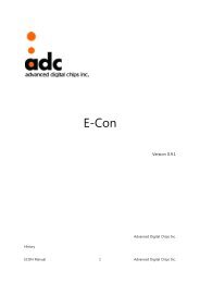
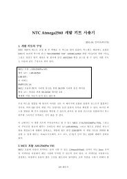
<strong>Topview</strong> <strong>5750</strong> <strong>SMD</strong> <strong>LED</strong><strong>IWS</strong>-<strong>506</strong>-<strong>RGB</strong>-<strong>K3</strong>8. Packing DimensionUnit :mm250Bake: 60°C, 4hrs220WheelLabelLabelDiameter : 180 mmWidth : 12 mm<strong>5750</strong> ⇒ 1,000 pcs/ReelShield Bag(Polyester/Al/LDPE)1 Reel / Bag ( T = 0.1 mm ) with Silica gelAl Pack & Reel Label, Box Label (70 × 37)Lot :VF[volt]IV[mcd]WD[nm]RANK #<strong>IWS</strong>-<strong>506</strong>-<strong>RGB</strong>-<strong>K3</strong>MIN AVG MAX STDCHIP <strong>LED</strong>Label226Q’ty :yyyy/mm/ddwww.itswell.com150224Maximum 10 Bags / 1Inner Box<strong>5750</strong> ⇒8,000 pcs/ 1 Inner Box<strong>IWS</strong> – <strong>506</strong>-<strong>RGB</strong>-<strong>K3</strong> Version of 2.0 PAGE : ‹#› / 13
Temp( ℃ )<strong>Topview</strong> <strong>5750</strong> <strong>SMD</strong> <strong>LED</strong><strong>IWS</strong>-<strong>506</strong>-<strong>RGB</strong>-<strong>K3</strong>9. Precaution in use9.1 Soldering Conditions• When soldering Power <strong>SMD</strong>, Heat may affect the electrical and optical characteristics of the<strong>LED</strong>s.• In soldering, do not stress the lead frame and the resin part under the high temperature.• The silicone part should be protected from mechanical stress or vibration until the Power <strong>SMD</strong>return to room temperature after soldering.▪ Preliminary heating to be at 200℃ max. for 120 Seconds max.▪ Soldering heat to be at 260℃ max. for 5sec. Max.▪ For manual Soldering is Not more than 3sec @MAX350℃, under soldering iron1-5℃/sec260℃, 5sec MaxUnit: mm1-5℃/secPre-heating180-200℃60sec. Max.Above 200℃120sec Max.9.2 StorageTime (sec.)• Use with 7days after opening packing. Store in 10 to 30 ℃ Power <strong>SMD</strong> lead frames areplated silver. The silver surface may be affected by environment which contain corrosivegases and so on. Please avoid condition which may cause thePower <strong>SMD</strong> to corroded, tarnish or discolor.9.3 Static Electricity• Static electricity or surge voltage damages the Power <strong>SMD</strong> . It is recommended that awrist band or an anti-electrostatic glove be used when handling the <strong>LED</strong>s.• A tip soldering iron is requested to be grounded. An ionizer should also be installed where riskof static.• All devices, equipment and machinery must be properly grounded (via 1MΩ). It isrecommended that measures be taken against surge voltage to the equipment that mounts thePower <strong>SMD</strong>.9.4 Cleaning• Isopropyl Alcohol or Ethylene Alcohol is recommended in 5 minutes at room temperature.Don’t use unspecified chemical may cause crack or haze on the surface of the epoxy resin.• Before cleaning, a pre-test should be done to confirm whether any damage to the <strong>LED</strong> will occur.• Freon solvents should not be used to clean the <strong>LED</strong>s because of worldwide regulations.<strong>IWS</strong> – <strong>506</strong>-<strong>RGB</strong>-<strong>K3</strong> Version of 2.0 PAGE : ‹#› / 13
<strong>Topview</strong> <strong>5750</strong> <strong>SMD</strong> <strong>LED</strong><strong>IWS</strong>-<strong>506</strong>-<strong>RGB</strong>-<strong>K3</strong>10. ReliabilityEach of <strong>RGB</strong>Test Items Test Conditions Notes10.1 Reliability Test ItemHigh Temperature Storage 100 ℃ , 500 hr. 0/32Low Temperature Storage -40 ℃ , 500 hr. 0/32Temp. Humidity Storage 60 ℃, 90 % RH, 500 hr. 0/32Steady State Operating lifeHigh TemperatureOperating LifeLow TemperatureOperating LifeSteady State Operating lifeOf High Humidity HeatTemperature CycleESDPressure Cooker Test25 ℃ , 30 mA , 500 hr.85 ℃ , 5 mA, 500 hr.-30 ℃ , 30 mA, 300 hr.60 ℃, 90 % RH, 10 mA, 300 hr.-40℃(30min) → 25(5min.)→ 100(30min.) → 25(5min.), 100 cycleHBM, 100pF, 1.5kohm, 3 times121 ℃, 2 atm., 99.6 % RH48 hr.0/320/320/320/320/220/220/2210.2 Criteria for Judging the DamageItems Test Conditions Criteria for judgmentLuminous Intensity ( IV )IF =20 mA> 70% of SForward Voltage ( VF ) IF =20 mAReverse Voltage ( V ZR ) I R =5 mALess than 120% of ULess than 120% of U* U means the upper limit of specified characteristics, S means initial value.<strong>IWS</strong> – <strong>506</strong>-<strong>RGB</strong>-<strong>K3</strong> Version of 2.0 PAGE : ‹#› / 13
<strong>Topview</strong> <strong>5750</strong> <strong>SMD</strong> <strong>LED</strong><strong>IWS</strong>-<strong>506</strong>-<strong>RGB</strong>-<strong>K3</strong>11. Part Name DescriptionI W S – <strong>506</strong> – <strong>RGB</strong> - <strong>K3</strong>Code designated by MakerRed, Green, Blue Color5.7mm x 5.0mm, 1.8mmt, 6-Pin<strong>SMD</strong> Type Chip <strong>LED</strong>Company Name, ITSWELL Co., Ltd.12. Rank DescriptionKLM AAA aaaVoltage Rank (<strong>RGB</strong>)Wavelength Rank (<strong>RGB</strong>)Luminous Intensity Rank (<strong>RGB</strong>)13. Attention : Electric Static Discharge (ESD) ProtectionThe symbol shown on the page herein to introduce ‘Electro-OpticalCharacteristics’. ESD protection for GaP, AlGaAs and SiC is based chips is stillnecessary even though they are safe in low static-electric discharge.Material in AlInGaP, GaP, or/and InGaN based chips are STATIC SENSITIVEdevices. ESD protection has to considered and taken in the initial design stage.If manual work/process is needed, please ensure the device is well protectiveFrom ESD during all the process.<strong>LED</strong>’s ESD Level is ‘Class II’ and the range of forward voltage is 2000V ~ 3999V.After opening the package, the <strong>LED</strong>’s should be kept at 30℃, 70%RH or less.The <strong>LED</strong>s must be dip soldered within seven days(168 hours) after opening the moisture-proof packing.It is better not to use different rank <strong>LED</strong>s.If use mixed rank, could not attain your object for highest quality of products.<strong>IWS</strong> – <strong>506</strong>-<strong>RGB</strong>-<strong>K3</strong> Version of 2.0 PAGE : ‹#› / 13
<strong>Topview</strong> <strong>5750</strong> <strong>SMD</strong> <strong>LED</strong><strong>IWS</strong>-<strong>506</strong>-<strong>RGB</strong>-<strong>K3</strong>■ Spec. Review HistoryReview Ver. Date Correction List Etc.Ver 1.0 2005.12. 27 EstablishVer 2.0 2006.04.13 SPEC 일부 조정Ver 2.1 2007.01.31 Iv수정<strong>IWS</strong> – <strong>506</strong>-<strong>RGB</strong>-<strong>K3</strong> Version of 2.0 PAGE : ‹#› / 13