MITSUBISHI QJ71MT91 Modbus TCP/IP
MITSUBISHI QJ71MT91 Modbus TCP/IP
MITSUBISHI QJ71MT91 Modbus TCP/IP

Create successful ePaper yourself
Turn your PDF publications into a flip-book with our unique Google optimized e-Paper software.
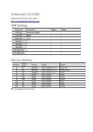
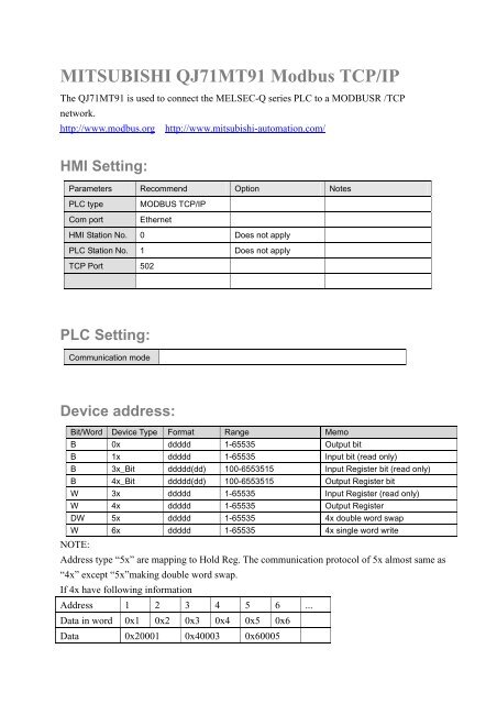
<strong>MITSUBISHI</strong> <strong>QJ71MT91</strong> <strong>Modbus</strong> <strong>TCP</strong>/<strong>IP</strong>The <strong>QJ71MT91</strong> is used to connect the MELSEC-Q series PLC to a MODBUSR /<strong>TCP</strong>network.http://www.modbus.org http://www.mitsubishi-automation.com/HMI Setting:Parameters Recommend Option NotesPLC typeCom portMODBUS <strong>TCP</strong>/<strong>IP</strong>EthernetHMI Station No. 0 Does not applyPLC Station No. 1 Does not apply<strong>TCP</strong> Port 502PLC Setting:Communication modeDevice address:Bit/Word Device Type Format Range MemoB 0x ddddd 1-65535 Output bitB 1x ddddd 1-65535 Input bit (read only)B 3x_Bit ddddd(dd) 100-6553515 Input Register bit (read only)B 4x_Bit ddddd(dd) 100-6553515 Output Register bitW 3x ddddd 1-65535 Input Register (read only)W 4x ddddd 1-65535 Output RegisterDW 5x ddddd 1-65535 4x double word swapW 6x ddddd 1-65535 4x single word writeNOTE:Address type “5x” are mapping to Hold Reg. The communication protocol of 5x almost same as“4x” except “5x”making double word swap.If 4x have following informationAddress 1 2 3 4 5 6 ...Data in word 0x1 0x2 0x3 0x4 0x5 0x6Data 0x20001 0x40003 0x60005
For 5x, it becomeAddress 1 2 3 4 5 6 ...Data in word 0x2 0x1 0x4 0x3 0x6 0x5Data 0x10002 0x30004 0x50006<strong>Modbus</strong> RTU function code:0x 0x01 Read coil 0x05 write single coil1x 0x02 Read discrete input N/A for write operation3x 0x04 Read input register N/A for write operation4x 0x03 Read holding register 0x10 write multiple register5x 0x03 Read holding register 0x10 write multiple register( note: reverse word order in double word format)3xbit is equivalent to 3x4xbit is equivalent to 4x6x 0x03 Read holding register 0x06 write single register( note: use 6x device is limited to device of one word only )Wiring diagram:Ethernet (to switch, hub or router):MT8000 Ethernet Wire colorRJ45Ethernet Hub or SwitchRJ451 TX+ White/Orange 1 RX+2 TX- Orange 2 RX-3 RX+ White/Green 3 TX+4 BD4+ Blue 4 BD4+5 BD4- White/Blue 5 BD4-6 RX- Green 6 TX-7 BD3+ White/Brown 7 BD3+8 BD3- Brown 8 BD3-1 8RJ45 connectorInternet orIntranetMT8000192.168.0.80Router192.168.0.1<strong>Modbus</strong> RTU <strong>TCP</strong>/<strong>IP</strong> Device210.68.117.224
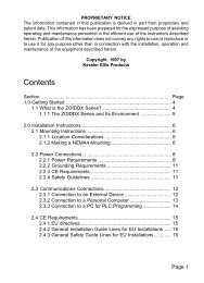
Ethernet: Direct connect (crossover cable)MT8000 Ethernet Wire colorRJ45<strong>Modbus</strong> <strong>TCP</strong> DeviceRJ451 TX+ White/Orange 3 RX+2 TX- Orange 6 RX-3 RX+ White/Green 1 TX+4 BD4+ Blue 4 BD4+5 BD4- White/Blue 5 BD4-6 RX- Green 2 TX-7 BD3+ White/Brown 7 BD3+8 BD3- Brown 8 BD3-MT8000192.168.0.80<strong>Modbus</strong> RTU <strong>TCP</strong>/<strong>IP</strong> Device192.168.0.154PLC Setting:1. Click “PLC parameter”2. Click “I/O assignment”3. Select “Intelli.” At slot 1.4. Click “Switch setting”
Entering the values in hexadecimal makes thesetting easy. Change the input format intoHEX before entering the values.C0A8 009A = 192.168.0.154After setting, write the data to the PLC, and powerthe PLC OFF, then ON or reset the PLC CPU.In GX Developer, click [Tools]/[Intelligent function utility]/[Start].Intelligent function module parameter setting module selectscreen.Enter "Start I/O No." and select "Module type" and"Module model name".Click [Initial setting]
Click [Basic parameter]Set Default router <strong>IP</strong> address.Click [End] setupClick [Online]/[Write to PLC]