instabus KNX/EIB System Sensor Continuous ... - Download - Gira
instabus KNX/EIB System Sensor Continuous ... - Download - Gira
instabus KNX/EIB System Sensor Continuous ... - Download - Gira

You also want an ePaper? Increase the reach of your titles
YUMPU automatically turns print PDFs into web optimized ePapers that Google loves.
<strong>instabus</strong> <strong>KNX</strong>/<strong>EIB</strong> <strong>System</strong><br />
<strong>Sensor</strong><br />
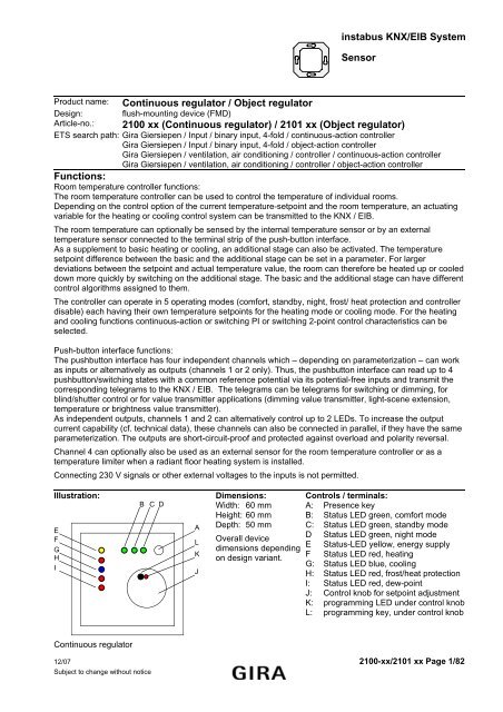
Product name: <strong>Continuous</strong> regulator / Object regulator<br />
Design: flush-mounting device (FMD)<br />
Article-no.: 2100 xx (<strong>Continuous</strong> regulator) / 2101 xx (Object regulator)<br />
ETS search path: <strong>Gira</strong> Giersiepen / Input / binary input, 4-fold / continuous-action controller<br />
<strong>Gira</strong> Giersiepen / Input / binary input, 4-fold / object-action controller<br />
<strong>Gira</strong> Giersiepen / ventilation, air conditioning / controller / continuous-action controller<br />
<strong>Gira</strong> Giersiepen / ventilation, air conditioning / controller / object-action controller<br />
Functions:<br />
Room temperature controller functions:<br />
The room temperature controller can be used to control the temperature of individual rooms.<br />
Depending on the control option of the current temperature-setpoint and the room temperature, an actuating<br />
variable for the heating or cooling control system can be transmitted to the <strong>KNX</strong> / <strong>EIB</strong>.<br />
The room temperature can optionally be sensed by the internal temperature sensor or by an external<br />
temperature sensor connected to the terminal strip of the push-button interface.<br />
As a supplement to basic heating or cooling, an additional stage can also be activated. The temperature<br />
setpoint difference between the basic and the additional stage can be set in a parameter. For larger<br />
deviations between the setpoint and actual temperature value, the room can therefore be heated up or cooled<br />
down more quickly by switching on the additional stage. The basic and the additional stage can have different<br />
control algorithms assigned to them.<br />
The controller can operate in 5 operating modes (comfort, standby, night, frost/ heat protection and controller<br />
disable) each having their own temperature setpoints for the heating mode or cooling mode. For the heating<br />
and cooling functions continuous-action or switching PI or switching 2-point control characteristics can be<br />
selected.<br />
Push-button interface functions:<br />
The pushbutton interface has four independent channels which – depending on parameterization – can work<br />
as inputs or alternatively as outputs (channels 1 or 2 only). Thus, the pushbutton interface can read up to 4<br />
pushbutton/switching states with a common reference potential via its potential-free inputs and transmit the<br />
corresponding telegrams to the <strong>KNX</strong> / <strong>EIB</strong>. The telegrams can be telegrams for switching or dimming, for<br />
blind/shutter control or for value transmitter applications (dimming value transmitter, light-scene extension,<br />
temperature or brightness value transmitter).<br />
As independent outputs, channels 1 and 2 can alternatively control up to 2 LEDs. To increase the output<br />
current capability (cf. technical data), these channels can also be connected in parallel, if they have the same<br />
parameterization. The outputs are short-circuit-proof and protected against overload and polarity reversal.<br />
Channel 4 can optionally also be used as an external sensor for the room temperature controller or as a<br />
temperature limiter when a radiant floor heating system is installed.<br />
Connecting 230 V signals or other external voltages to the inputs is not permitted.<br />
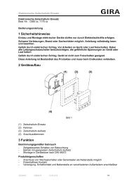
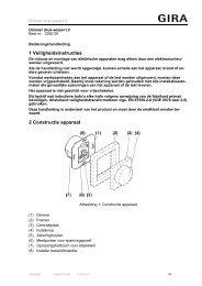
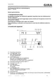
Illustration: Dimensions: Controls / terminals:<br />
B C D<br />
Width: 60 mm A: Presence key<br />
Height: 60 mm B: Status LED green, comfort mode<br />
E<br />
F<br />
G<br />
H<br />
I<br />
A<br />
L<br />
K<br />
J<br />
Depth: 50 mm C:<br />
Overall device<br />
D<br />
dimensions depending<br />
E<br />
on design variant.<br />
F<br />
G:<br />
H:<br />
Status LED green, standby mode<br />
Status LED green, night mode<br />
Status-LED yellow, energy supply<br />
Status LED red, heating<br />
Status LED blue, cooling<br />
Status LED red, frost/heat protection<br />
I: Status LED red, dew-point<br />
J: Control knob for setpoint adjustment<br />
K: programming LED under control knob<br />
L: programming key, under control knob<br />
<strong>Continuous</strong> regulator<br />
12/07 2100-xx/2101 xx Page 1/82<br />
Subject to change without notice
<strong>instabus</strong> <strong>KNX</strong>/<strong>EIB</strong> <strong>System</strong><br />
<strong>Sensor</strong><br />
Object controller<br />
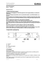
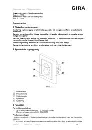
The continuous-action controller is also available without control elements. This variant is called object<br />
controller. This means that the object controller has no status LEDs (B - I) no presence key (A) and no control<br />
knob (J). The room temperature controller and pushbutton interface functions are however the same as in the<br />
continuous-action controller. The room temperature controller function of the object controller is operated<br />
exclusively by means of telegrams via the bus.<br />
(The object controller has other article nos. and similar ETS search paths.)<br />
Illustration: Dimensions: Controls / terminals:<br />
Width: 60 mm<br />
Height: 60 mm<br />
Depth: 50 mm<br />
Overall device<br />
dimensions depending<br />
on design variant.<br />
–<br />
Object controller<br />
2/82 Page 2100-xx/2101 xx 12/07<br />
Subject to change without notice
<strong>instabus</strong> <strong>KNX</strong>/<strong>EIB</strong> <strong>System</strong><br />
<strong>Sensor</strong><br />
Technische Daten:<br />
Instabus <strong>EIB</strong> supply<br />
Voltage: 21 – 32 V DC<br />
Power consumption: typically 150 mW<br />
Connection: bus connecting terminal (<strong>KNX</strong> type 5.1)<br />
External supply --room<br />
temperature controller<br />
(internal temperature sensor):<br />
Measuring range: 0 °C … + 40 °C ±1 %<br />
Resolution: 0.1 K<br />
Air humidity: 0 % ... 95 % (no condensation)<br />
Response to bus voltage failure<br />
Bus voltage only: all object values will be deleted.<br />
room temperature controller: no response, control off<br />
pushbutton interface no response (outputs switched off)<br />
Mains voltage only: ---<br />
Bus and mains voltage: ---<br />
Response on return of voltage<br />
Bus voltage only: room temperature controller: the controller is initialized;<br />
depending on parameterization, different temperature values and the<br />
status will be transmitted and the switch-over objects will be updated.<br />
pushbutton interface the behaviour of the inputs and outputs can be<br />
parameterized.<br />
Mains voltage only: ---<br />
Bus and mains voltage: ---<br />
Input:<br />
Number: up to 4 (depending on parameterization: channel 1 to 4)<br />
Connection screw terminals 0.3 mm² to 1.5 mm² single-wire<br />
max. 1.0 mm² single-wire without ferrule<br />
Cable length: binary inputs: max. 5 m<br />
external temperature sensor: 4 m prefabricated, extendible up to 50 m<br />
max.<br />
Scanning voltage: continuous signal<br />
Loop resistance: 2 kohms max. for safe detection of a "1" signal (rising edge)<br />
Output:<br />
Number: up to 2 (depending on parameterization: channel 1 and/or 2)<br />
Cable length: max. 5 m<br />
Output current: max. 0.8 mA per output channel<br />
(at 1.5 V; typically for red low-current LED)<br />
for parallel connection, the maximum total current rises to 1.6 mA For<br />
parallel connection it is indispensable that outputs 1 and 2 have exactly<br />
the same parameterization (none of the output signal must be a<br />
blinking signal!). The outputs are protected against short-circuits,<br />
overload and polarity reversal.<br />
Output voltage: typically 1.5 V (e.g. red low-current LED)<br />
(5 V output open circuit)<br />
Type of protection: IP 20<br />
Safety class: III<br />
Mark of approval: <strong>KNX</strong> / <strong>EIB</strong><br />
Ambient temperature: -5 °C ... +45 °C<br />
Storage / transport temperature: -25 °C ... +70 °C (storage above +45 °C reduces the lifetime)<br />
Mounting position: any<br />
Minimum distances: none<br />
Type of fastening: The connection insert module with its supporting ring is fastened with<br />
screws in the flush-mounting box. The electronic module is plugged<br />
into the insert module.<br />
12/07 2100-xx/2101 xx Page 3/82<br />
Subject to change without notice
<strong>instabus</strong> <strong>KNX</strong>/<strong>EIB</strong> <strong>System</strong><br />
<strong>Sensor</strong><br />
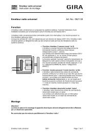
Wiring diagram / Terminals:<br />
Example 1: implementation of 4 binary inputs<br />
recommended cable type:<br />
binary inputs 1 … 4: J-Y(St)Y 2 x 2 x 0.8 mm<br />
1<br />
2<br />
3<br />
4<br />
5<br />
6<br />
Example 2: implementation of 2 binary outputs,. 1 binary input, external temperature sensor<br />
recommended cable type:<br />
binary outputs: J-Y(St)Y 2 x 2 x 0.8 mm binary input: J-Y(St)Y 2 x 2 x 0.8 mm<br />
temperature sensor: 0.75 mm 2 stranded wire without ferrule (prefabricated connecting cable)<br />
1.5 mm 2 single-wire (for extension of the prefabricated cable to 50 m max.)<br />
1<br />
2<br />
3<br />
4<br />
5<br />
6<br />
Hardware information<br />
• With 1.5 mm² cross-section, a deep flush-mounting box is required.<br />
• Connection of sensor wires (terminal 1-5):<br />
A suitable cable must be selected if the sensor lines are to be laid under the surface.<br />
Recommendation: telephone cable J-Y(St)Y 2 x 2 x 0.8 mm.<br />
V<br />
• Connection of temperature sensor (terminal 5-6)<br />
Use of sensor cable 2 x 0.75 mm² without ferrule.<br />
The sensor cable can be extended to 50 m max. by using twisted pair cable, e.g. J-Y(St)Y-2x2x0.8<br />
4/82 Page 2100-xx/2101 xx 12/07<br />
Subject to change without notice
<strong>instabus</strong> <strong>KNX</strong>/<strong>EIB</strong> <strong>System</strong><br />
<strong>Sensor</strong><br />
Software description:<br />
ETS search path:<br />
<strong>Gira</strong> Giersiepen / Input / binary input, 4-fold / continuous-action controller<br />
<strong>Gira</strong> Giersiepen / ventilation, air conditioning / controller / continuous-action controller<br />
<strong>Gira</strong> Giersiepen / Input / binary input, 4-fold / object-action controller<br />
<strong>Gira</strong> Giersiepen / ventilation, air conditioning / controller / object-action controller<br />
Applications:<br />
Short description: Name: Date: Page: Version:<br />
Room temperature controller with pushbutton<br />
interface<br />
<strong>Continuous</strong>-action controller with<br />
pushbutton interface 4-fold<br />
705C01 (ETS 2)<br />
<strong>Continuous</strong>-action controller with<br />
pushbutton interface 4-fold<br />
705C10 (ETS 3)<br />
12.06 6 0.1<br />
12/07 2100-xx/2101 xx Page 5/82<br />
Subject to change without notice
<strong>instabus</strong> <strong>KNX</strong>/<strong>EIB</strong> <strong>System</strong><br />
<strong>Sensor</strong><br />
Application: <strong>Continuous</strong>-action controller with pushbutton interface, 4-fold 705C<br />
Scope of functions<br />
Pushbutton interface functions:<br />
General<br />
• Switching, dimming, shutter/blind and value transmitter functions freely assignable to the max. 4 inputs<br />
• Disable object for disabling of individual inputs (polarity of disable object presettable)<br />
• Delay on return of bus voltage and debouncing time centrally adjustable<br />
• Response to bus voltage return separately parameterizable for each input<br />
• Telegram rate limitation generally parameterizable for all inputs<br />
Switching function<br />
• Two independent switching objects available for each input (switching commands individually<br />
parameterizable)<br />
• Command for rising and falling edge individually adjustable (ON, OFF, TOGGLE, no reaction).<br />
• Independent cyclical transmission of switching objects depending on edge or on object value selectable.<br />
Dimming function<br />
• Single-sided and double-sided actuation<br />
• Time between dimming and switching and dimming step width presettable<br />
• Telegram repetition and stop telegram transmission possible<br />
Shutter/blind function<br />
• Command on rising edge adjustable (no function, UP, DOWN, TOGGLE)<br />
• Operation concept parameterizable ("step - move – step" resp. "move – step")<br />
• Time between short-time and long-time operation presettable (only with "step - move - step")<br />
• Slat adjustment time presettable (time during which a "Move" command can be terminated by releasing a<br />
push-button on the input)<br />
Dimming value transmitter function<br />
• Nature of edge (push-button as make contact, push-button as break contact, switch) and value of edge<br />
parameterizable<br />
• Value change in push-button mode possible with long press on the button for value transmitter<br />
Light-scene extension function<br />
• Nature of edge (push-button as n.o. contact, push-button as n.c. contact, switch) and value of edge<br />
parameterizable<br />
• Value adjustment via long key press possible<br />
• In light-scene extension with storage function, a light-scene can be stored without preceding recall<br />
Temperature and brightness value transmitter<br />
• Nature of edge (push-button as n.o. contact, push-button as n.c. contact, switch) and value of edge<br />
parameterizable<br />
• Value change in push-button mode possible with long press on the button<br />
Temperature sensor function<br />
• Channel 4 of the pushbutton interface can be used as external temperature sensor for the room<br />
temperature controller.<br />
Outputs:<br />
• Independent switching of the maximum of 2 outputs<br />
• Optionally output of a 1-bit actuating variable of the room temperature controller or a separate switching<br />
object.<br />
• The current switching status of the output can be issued for status indication purposes via a 1-bit object.<br />
6/82 Page 2100-xx/2101 xx 12/07<br />
Subject to change without notice
<strong>instabus</strong> <strong>KNX</strong>/<strong>EIB</strong> <strong>System</strong><br />
<strong>Sensor</strong><br />
Room temperature controller functions:<br />
General<br />
• 5 operating modes: Comfort, standby, night, frost/heat protection and controller disable<br />
• Operating modes switch-over via 1-byte object according to KONNEX or individual 1-bit objects.<br />
Heating/cooling system<br />
• Control options: heating", "cooling", "heating and cooling" each with or without additional stage.<br />
• PI control (continuous or switching PWM) or 2-state control (switching) adjustable as control algorithms.<br />
• <strong>Continuous</strong> (1-byte) or switching (1-bit) actuating variable output.<br />
• Control parameter for PI controller (if desired: proportional range, integral-action time) and 2-state<br />
controller (hysteresis) presettable.<br />
Setpoint values<br />
• Each operating mode can be assigned its own temperature setpoints (for heating and/or cooling).<br />
• The setpoints for the additional stage are derived via a parameterizable stage offset from the values of<br />
the basic stage.<br />
• Setpoint value shifting by local operation on device or via communication objects.<br />
Functions<br />
• Automatic or object-oriented switch-over between "heating" and "cooling".<br />
• The controller operation can optionally be disabled via an object.<br />
• Parameterizable duration of the comfort mode extension.<br />
• Complete (1-byte) or partial (1-bit) status information parameterizable and transmissible to the bus via an<br />
object.<br />
• Deactivation of the control or of the additional stage via different objects possible.<br />
Room temperature measurement<br />
• Internal and external room temperature sensor available.<br />
• Internal to external determination of measured value with enabled external sensor.<br />
• Request interval of external temperature sensor adjustable.<br />
• The actual and setpoint temperature can be output to the bus if a parameterizable deviation is detected<br />
(also cyclically).<br />
• The room temperature measurement (actual value) can be adjusted separately for the internal and<br />
external sensor via parameter.<br />
• Frost/heat protection switch-over depending on window state.<br />
• Temperature alarm with upper and lower temperature limit possible. Telegram activation via two separate<br />
objects.<br />
Actuating variable output<br />
• Separate or combined actuating variable output via one or two objects in "heating and cooling" mode<br />
• Normal or inverted actuating variable output parameterizable<br />
• Automatic transmission and cycle time for actuating output parameterizable<br />
12/07 2100-xx/2101 xx Page 7/82<br />
Subject to change without notice
<strong>instabus</strong> <strong>KNX</strong>/<strong>EIB</strong> <strong>System</strong><br />
<strong>Sensor</strong><br />
Objects for the pushbutton interface:<br />
Object Object description<br />
0 – 3 Switching object X.1 1-bit object for transmission of switching telegrams (ON, OFF)<br />
(1st switching object)<br />
4 – 7 Switching object X.2 1-bit object for transmission of switching telegrams (ON, OFF)<br />
(2nd switching object)<br />
0 – 3 Switching: 1- bit object for transmitting switching telegrams (ON, OFF) for the<br />
dimming function<br />
4 – 7 Dimming: 4-bit object for relative brightness variation between 0 and 100 %<br />
0 – 3 Short-time operation 1-bit object for short-time operation of a blind/shutter<br />
4 – 7 Long-time operation 1-bit object for long-time operation of a blind/shutter<br />
0 – 3 Value: 1-byte object for the transmission of value telegrams (0 - 255)<br />
0 – 3 Light-scene extension: 1-byte object for recalling and storing light-scenes (1 - 64)<br />
0 – 3 Temperature value: 2-byte object for adjusting a fixed temperature value (0 - 40 °C)<br />
0 – 3 Brightness value: 2-byte object for adjusting a fixed brightness value between 0 and<br />
1500<br />
8 – 11 Disabling: 1-bit object for disabling individual binary inputs<br />
(polarity parameterizable)<br />
8 – 11 Disabling Switching<br />
object X.1<br />
12 - 15 Disabling Switching<br />
object X.2<br />
1-bit object for disabling individual binary inputs<br />
(polarity parameterizable)<br />
1-bit object for disabling individual binary inputs<br />
(polarity parameterizable)<br />
3 Floor temperature: 2-byte object for transmitting the current floor temperature when the<br />
temperature limiter is operational<br />
4 – 5 External switching<br />
object:<br />
1-bit object for control of an (LED) output<br />
0 – 1 Switching: 1-bit object for switching status feedback of an output<br />
8/82 Page 2100-xx/2101 xx 12/07<br />
Subject to change without notice
<strong>instabus</strong> <strong>KNX</strong>/<strong>EIB</strong> <strong>System</strong><br />
<strong>Sensor</strong><br />
Objects for the room temperature controller:<br />
Object Object description<br />
23 Actual temperature: 2-byte object for transmission of the actual temperature (room<br />
temperature) as measured and varied by a controller or a controller<br />
extension.<br />
(possible range of values: -99.9 °C ... +99.9 °C /<br />
Measuring range of internal temperature sensor:<br />
0 °C ... + 40 °C (1 %)<br />
24 External temperature<br />
sensor<br />
2-byte object for connection of an external room temperature sensor<br />
or a controller extension (via "actual temperature" object).<br />
(possible range of values: -99.9 °C ... +99.9 °C)<br />
26 Basic setpoint: 2-byte object for external preset of basic setpoint.<br />
Depending on heating/cooling, the possible range of values is limited<br />
by the parameterized frost protection and/or heat protection<br />
temperature. The received value is mathematically rounded off to<br />
half °C!<br />
28 Operating mode<br />
switch-over:<br />
1-byte object for switch-over of the controller’s operating modes acc.<br />
to KONNEX.<br />
28 Comfort operation: 1-bit object for switch-over into the "Comfort" operating mode.<br />
29 Standby operation: 1-bit object for switch-over into the "Standby" operating mode.<br />
30 Night-time operation: 1-bit object for switch-over into the "Night" operating mode.<br />
31 Frost/ heat protection: 1-bit object for switch-over into the "Frost/heat protection" operating<br />
mode.<br />
32 Forced-control object<br />
operating mode:<br />
1-byte object for superordinated forced control of the controller’s<br />
operating modes acc. to KONNEX.<br />
33 Presence object: 1-bit object (bi-directional) which transmits the status of the<br />
presence key to the bus after pressing or which can be used for<br />
connection of a presence detector.<br />
(presence detected = "1", presence not detected = "0")<br />
34 Window status: 1-bit object for the connection of window contacts.<br />
(window open = "1", window closed = "0")<br />
35 Heating / cooling<br />
change-over:<br />
1-bit object for switching over between control options "heating" and<br />
"cooling, if not done by the controller automatically<br />
(object value 1: heating; object value 0: cooling).<br />
In case of automatic switch-over the active control option can be<br />
transmitted (parameter-dependent).<br />
36 Controller status: 1-byte object for general status feedback<br />
36 Controller status: 1-bit object for individual status feedback of parameterizable<br />
functions of the controller (frost alarm, heating/cooling, comfort<br />
mode, night mode, standby mode, controller disabled, controller<br />
inactive, frost/heat protection).<br />
12/07 2100-xx/2101 xx Page 9/82<br />
Subject to change without notice
<strong>instabus</strong> <strong>KNX</strong>/<strong>EIB</strong> <strong>System</strong><br />
<strong>Sensor</strong><br />
37 Message heating: 1-bit object for the controller to indicate a request for heating energy<br />
(object value = "1": energy request, object value = "0": no energy<br />
request).<br />
38 Message cooling: 1-bit object for the controller to indicate a cooling energy request<br />
(object value = "1": energy request, object value = "0": no energy<br />
request).<br />
40 Controller disable: 1-bit object for deactivating the controller (activation of dew-point<br />
operation). (controller deactivated = "1", controller activated = "0")<br />
41 Additional stage<br />
disable:<br />
42 Actuating variable<br />
heating:<br />
42 Actuating variable<br />
heating:<br />
42 Actuating variable<br />
heating<br />
(PWM):<br />
42 Actuating variable<br />
basic heating:<br />
42 Actuating variable<br />
basic heating:<br />
42 Actuating variable<br />
basic heating (PWM) :<br />
42 Actuating variable<br />
heating/cooling:<br />
42 Actuating variable<br />
heating/cooling:<br />
1-bit object for deactivating the additional stage of the controller.<br />
(additional stage deactivated = "1", additional stage activated = "0")<br />
1-byte object for the output of the continuous actuating variable for<br />
heating operation.<br />
1-bit object for the output of the continuous actuating variable for<br />
heating operation.<br />
1-bit object for the output of the continuous PWM actuating variable<br />
for heating operation.<br />
1-byte object for the output of the continuous actuating variable for<br />
basic heating operation.<br />
1-bit object for the output of the continuous actuating variable for<br />
basic heating operation.<br />
1-bit object for the output of the continuous PWM actuating variable<br />
for basic heating operation.<br />
1-byte object for the output of the continuous actuating variable for<br />
heating or for cooling operation.<br />
(via shared object if actuating variables are output)<br />
1-bit object for the output of the switching variable for heating or for<br />
cooling operation.(via shared object if actuating variables are output)<br />
42 Actuating variable 1-bit object for the output of the PWM actuating variable for heating<br />
heating/cooling (PWM): or for cooling operation.<br />
(via shared object if actuating variables are output)<br />
42 Actuating variable<br />
basic heating and<br />
cooling:<br />
42 Actuating variable<br />
basic heating and<br />
cooling:<br />
42 Actuating variable<br />
basic heating and<br />
cooling: (PWM):<br />
1-byte object for the output of the continuous actuating variable<br />
either for basic heating or for basic cooling operation<br />
(via shared object if actuating variables are output)<br />
1-bit object for the output of the switching variable either for basic<br />
heating or for basic cooling operation<br />
(via shared object if actuating variables are output)<br />
1-bit object for the output of the PWM actuating variable either for<br />
basic heating or for basic cooling operation<br />
(via shared object if actuating variables are output)<br />
10/82 Page 2100-xx/2101 xx 12/07<br />
Subject to change without notice
43 Actuating variable<br />
additional heating:<br />
43 Actuating variable<br />
additional heating:<br />
43 Actuating variable<br />
additional heating<br />
(PWM):<br />
43 Actuating variable<br />
additional heating and<br />
cooling:<br />
43 Actuating variable<br />
additional heating and<br />
cooling:<br />
43 Actuating variable<br />
additional heating and<br />
cooling: (PWM):<br />
44 Actuating variable<br />
cooling:<br />
44 Actuating variable<br />
cooling:<br />
44 Actuating variable<br />
cooling (PWM):<br />
44 Actuating variable<br />
basic cooling:<br />
44 Actuating variable<br />
basic cooling:<br />
44 Actuating variable<br />
basic cooling (PWM):<br />
45 Actuating variable<br />
additional cooling:<br />
45 Actuating variable<br />
additional cooling:<br />
45 Actuating variable<br />
additional cooling<br />
(PWM):<br />
46 PWM actuating<br />
variable Heating:<br />
46 PWM actuating<br />
variable Basic heating:<br />
<strong>instabus</strong> <strong>KNX</strong>/<strong>EIB</strong> <strong>System</strong><br />
<strong>Sensor</strong><br />
1-byte object for the output of the continuous actuating variable for<br />
additional heating operation.<br />
1-bit object for the output of the switching variable for heating<br />
operation.<br />
1-bit object for the output of the PWM actuating variable for<br />
additional heating operation<br />
1-byte object for the output of the continuous actuating variable<br />
either for additional heating or cooling operation<br />
(via shared object if actuating variables are output)<br />
1-bit object for the output of the switching variable either for<br />
additional heating or cooling operation<br />
(via shared object if actuating variables are output)<br />
1-bit object for the output of the PWM actuating variable either for<br />
additional heating or cooling operation<br />
(via shared object if actuating variables are output)<br />
1-byte object for the output of the continuous actuating variable for<br />
cooling operation.<br />
1-bit object for the output of the switching variable for heating<br />
operation.<br />
1-bit object for the output of the PWM actuating variable for cooling<br />
operation<br />
1-byte object for the output of the continuous actuating variable for<br />
basic cooling operation<br />
1-bit object for the output of the switching variable for basic cooling<br />
operation<br />
1-bit object for the output of the PWM actuating variable for basic<br />
cooling operation<br />
1-byte object for the output of the continuous actuating variable for<br />
additional cooling operation<br />
1-bit object for the output of the switching variable for additional<br />
heating operation.<br />
1-bit object for the output of the PWM actuating variable for<br />
additional cooling operation.<br />
1-byte object with PWM actuating variable for status feedback of the<br />
actuating variable value for heating operation<br />
1-byte object with PWM actuating variable for status feedback of the<br />
continuous actuating variable value for basic heating operation<br />
12/07 2100-xx/2101 xx Page 11/82<br />
Subject to change without notice
<strong>instabus</strong> <strong>KNX</strong>/<strong>EIB</strong> <strong>System</strong><br />
<strong>Sensor</strong><br />
47 PWM actuating<br />
variable Additional<br />
heating:<br />
48 PWM actuating<br />
variable Cooling:<br />
48 PWM actuating<br />
variable Basic cooling:<br />
49 PWM actuating<br />
variable Additional<br />
cooling:<br />
1-byte object with PWM actuating variable for status feedback of the<br />
continuous actuating variable value for additional heating..<br />
1-byte object with PWM actuating variable for status feedback of the<br />
continuous actuating variable value for cooling operation<br />
1-byte object with PWM actuating variable for status feedback of the<br />
continuous actuating variable value for basic cooling operation<br />
1-byte object with PWM actuating variable for status feedback of the<br />
continuous actuating variable value for additional cooling operation<br />
50 Setpoint temperature: 2-byte object for the output of the current temperature.<br />
Depending on the control option, the possible range of values is<br />
limited by the parameterized frost protection and/or heat protection<br />
temperature.<br />
50 Setpoint temperature: 2-byte object for receiving the current temperature setpoint of a<br />
controller.<br />
52 Feedback setpoint<br />
shift:<br />
1-byte object for current setpoint shift feedback<br />
x ≤ 0 ≤ y (0 = no active shifting); integers<br />
The possible range of values (x to y) is fixed by the setting of the<br />
upper and lower limits for the setpoint (parameterizable) in<br />
combination with the step value (0.5 °C).<br />
53 Preset setpoint shift 1-byte object for presetting a basic setpoint shift, e.g. via a controller<br />
extension.<br />
x ≤ 0 ≤ y (0 = no active shifting); integers<br />
The possible range of values (x to y) is fixed by the setting of the<br />
upper and lower limits for the setpoint (parameterizable) in<br />
combination with the step value (0.5 °C).<br />
In case the limits of the value range are exceeded by the preset<br />
external value, the controller will automatically reset the received<br />
value to the minimum and maximum limits.<br />
57 Additional status<br />
feedback<br />
58 Actual temperature not<br />
adjusted<br />
1-byte object for general additional status feedback<br />
2-byte object for the output of the actual temperature (room<br />
temperature) as measured and not adjusted by the controller.<br />
(possible range of values: -99.9 °C ... +99.9 °C /<br />
Measuring range of internal temperature sensor:<br />
0 °C to + 40 °C ±1 %)<br />
12/82 Page 2100-xx/2101 xx 12/07<br />
Subject to change without notice
<strong>instabus</strong> <strong>KNX</strong>/<strong>EIB</strong> <strong>System</strong><br />
<strong>Sensor</strong><br />
Number of addresses (max): 120 dynamic table handling Yes � No �<br />
Number of assignments (max): 120 maximum length of table 120<br />
Communication objects: 59<br />
Pushbutton interface functions:<br />
Function: Binary input / switching (for all 4 binary inputs (X = 1 to 4)) disabling function enabled<br />
Object-Nr. Function Name DPT–ID Type Flag<br />
0-3 Switching object X.1 PBI input X 1.001 1 bit C, T<br />
4-7 Switching object X.2 PBI input X 1.001 1 bit C, T<br />
8-11 Disable switching object X.1 PBI input X 1.001 1 bit C, W<br />
12-15 Disable switching object X.2 PBI input X 1.001 1 bit C, W<br />
Function: Binary input / dimming (for all 4 binary inputs (X = 1 to 4)) disabling function enabled<br />
Object-Nr. Function Name DPT–ID Type Flag<br />
0-3 Switching PBI input X 1.001 1 bit C, T<br />
4-7 dimming PBI input X 3.007 4 bit C, T<br />
8-11 Disabling PBI input X 1.001 1 bit C, W<br />
Function: Binary input / blind/shutter (for all 4 binary inputs (X = 1 to 4)) disabling function enabled<br />
Object-Nr. Function Name DPT–ID Type Flag<br />
0-3 Short-time operation PBI input X 1.007 1 bit C, T<br />
4-7 Long-time operation PBI input X 1.008 1 bit C, T<br />
8-11 Disabling PBI input X 1.001 1 bit C, W<br />
Function: Binary input / dimming value transmitter (for all 4 binary inputs (X = 1 to 4)) disabling function<br />
enabled<br />
Object-Nr. Function Name DPT–ID Type Flag<br />
0-3 Value PBI input X 5.001 1 byte C, T<br />
8-11 Disabling PBI input X 1.001 1 bit C, W<br />
Function: Binary input / light-scene extension (for all 4 binary inputs (X = 1 to 4)) disabling function<br />
enabled<br />
Object-Nr. Function Name DPT–ID Type Flag<br />
0-3 Light-scene extension PBI input X 18.001 1 byte C, T<br />
8-11 Disabling PBI input X 1.001 1 bit C, W<br />
Function: Binary input / brightness value transmitter (for all 4 binary inputs (X = 1 to 4)) disabling function<br />
enabled<br />
Object-Nr. Function Name DPT–ID Type Flag<br />
0-3 Brightness value PBI input X 9.004 2 bytes C, T<br />
8-11 Disabling PBI input X 1.001 1 bit C, W<br />
12/07 2100-xx/2101 xx Page 13/82<br />
Subject to change without notice
<strong>instabus</strong> <strong>KNX</strong>/<strong>EIB</strong> <strong>System</strong><br />
<strong>Sensor</strong><br />
Function: Binary input / temperature value transmitter (for all 4 binary inputs (X = 1 to 4))<br />
disabling function enabled<br />
Object-Nr. Function Name DPT–ID Type Flag<br />
0-3 Temperature value PBI input X 9.001 2 bytes C, T<br />
8-11 Disabling PBI input X 1.001 1 bit C, W<br />
Function: output / basic stage ... or additional stage ... (for channels 1 and 2 (Y = 1 to 2))<br />
Object-Nr. Function Name DPT–ID Type Flag<br />
0-1 Switching PBI output Y 1.001 1 bit C, T<br />
Function: output / output external switching object ... (for channels 1 and 2 (Y = 1 to 2))<br />
Object-Nr. Function Name DPT–ID Type Flag<br />
0-1 Switching PBI output Y 1.001 1 bit C, T<br />
4-5 external switching object PBI output Y 1.001 1 bit C, W<br />
Function: external temperature sensor (for channel 4)<br />
Object-Nr. Function Name DPT–ID Type Flag<br />
If channel 4 is used as an external temperature sensor for the room temperature controller, its measuring<br />
value is internally written into communication object 24 "External temperature sensor" of the controller. To<br />
avoid malfunctions, it is not permitted to write other values from outside into this object.<br />
Function: temperature limiter (for channel 4)<br />
Object-Nr. Function Name DPT–ID Type Flag<br />
3 floor temperature PBI input 4 9.001 2 bytes C, T<br />
14/82 Page 2100-xx/2101 xx 12/07<br />
Subject to change without notice
Room temperature controller functions:<br />
Function: Actual temperature<br />
<strong>instabus</strong> <strong>KNX</strong>/<strong>EIB</strong> <strong>System</strong><br />
<strong>Sensor</strong><br />
Object-Nr. Function Name DPT–ID Type Flag<br />
23 Actual temperature RTC output 9.001 2 bytes C, R, T<br />
Function: additional temperature sensor<br />
Object-Nr. Function Name DPT–ID Type Flag<br />
24 External temperature sensor RTC input 9.001 2 bytes C, W, T<br />
Function: basic setpoint preset<br />
Object-Nr. Function Name DPT–ID Type Flag<br />
26 Basic setpoint RTC input 9.001 2 bytes C, W<br />
Function: Operating mode switch-over<br />
With operating mode switch-over "via value (1 byte)":<br />
Object-Nr. Function Name DPT–ID Type Flag<br />
28 Operating mode switch-over RTC input 20.102 1 byte C, W(, T) 1<br />
32 Operating mode forcing object RTC input 20.102 1 byte C, W<br />
With operating mode switch-over "via switching (4 x 1 bit)":<br />
Object-Nr. Function Name DPT–ID Type Flag<br />
28 Comfort mode RTC input 1.001 1 bit C, W(, T) 1<br />
29 Standby mode RTC input 1.001 1 bit C, W(, T) 1<br />
30 Night mode RTC input 1.001 1 bit C, W(, T) 1<br />
31 Frost/ heat protection RTC input 1.001 1 bit C, W(, T) 1<br />
Presence object and window status:<br />
Object-Nr. Function Name DPT–ID Type Flag<br />
33 Presence object RTC input / output 1.001 1 bit C, W, T<br />
34 Window status RTC input 1.019 1 bit C, W<br />
Function: Control option switch-over<br />
Object-Nr. Function Name DPT–ID Type Flag<br />
35 Heating / cooling switch-over 2 RTC input 1.001 1 bit C, W, (T)<br />
12/07 2100-xx/2101 xx Page 15/82<br />
Subject to change without notice
<strong>instabus</strong> <strong>KNX</strong>/<strong>EIB</strong> <strong>System</strong><br />
<strong>Sensor</strong><br />
Function: Status indication<br />
Object-Nr. Function Name DPT–ID Type Flag<br />
36 Controller status RTC output --- 1 byte C, T<br />
36 Controller status, frost alarm RTC output 1.001 1 bit C, T<br />
36 Controller status, heating /<br />
cooling<br />
RTC output 1.001 1 bit C, T<br />
36 Controller status, comfort<br />
mode<br />
RTC output 1.001 1 bit C, T<br />
36 Controller status, night mode RTC output 1.001 1 bit C, T<br />
36 Controller status, controller<br />
disabled<br />
RTC output 1.001 1 bit C, T<br />
36 Controller status, controller<br />
inactive<br />
RTC output 1.001 1 bit C, T<br />
36 Controller status, frost / heat<br />
protection<br />
RTC output 1.001 1 bit C, T<br />
36 Controller status, standby<br />
mode<br />
RTC output 1.001 1 bit C, T<br />
37 Heating message RTC output 1.001 1 bit C, T<br />
38 Cooling message RTC output 1.001 1 bit C, T<br />
Function: Disabling function (room temperature controller)<br />
Object-Nr. Function Name DPT–ID Type Flag<br />
40 Disable controller RTC input 1.001 1 bit C, W<br />
41 Disable additional stage 3 RTC input 1.001 1 bit C, W<br />
Function: Actuating variable heating<br />
no additional stage activated /<br />
For mixed operation: Actuating variable output "heating" and "cooling" via separate objects:<br />
Object-Nr. Function Name DPT–ID Type Flag<br />
42 Actuating variable heating RTC output 5.001 1 byte C, W, T<br />
42 Actuating variable heating<br />
(PWM)<br />
RTC output 1.001 1 bit C, W, T<br />
42 Actuating variable heating RTC output 1.001 1 bit C, W, T<br />
no additional stage activated /<br />
For mixed operation: Actuating variable output "heating" and "cooling" via shared object:<br />
Object-Nr. Function Name DPT–ID Type Flag<br />
42 Actuating variable<br />
heating/cooling<br />
RTC output 5.001 1 byte C, W, T<br />
42 Actuating variable<br />
heating/cooling (PWM)<br />
RTC output 1.001 1 bit C, W, T<br />
42 Actuating variable<br />
heating/cooling<br />
RTC output 1.001 1 bit C, W, T<br />
16/82 Page 2100-xx/2101 xx 12/07<br />
Subject to change without notice
<strong>instabus</strong> <strong>KNX</strong>/<strong>EIB</strong> <strong>System</strong><br />
<strong>Sensor</strong><br />
additional stage activated /<br />
For mixed operation: Actuating variable output "heating" and "cooling" via separate objects:<br />
Object-Nr. Function Name DPT–ID Type Flag<br />
42 Actuating variable RTC output 5.001 1 byte C, W, T<br />
42 Actuating variable basic<br />
heating (PWM)<br />
42 Actuating variable basic<br />
heating<br />
43 Actuating variable additional<br />
heating<br />
43 Actuating variable additional<br />
heating (PWM)<br />
43 Actuating variable additional<br />
heating<br />
RTC output 1.001 1 bit C, W, T<br />
RTC output 1.001 1 bit C, W, T<br />
RTC output 5.001 1 byte C, W, T<br />
RTC output 1.001 1 bit C, W, T<br />
RTC output 1.001 1 bit C, W, T<br />
Additional stage activated /<br />
For mixed operation: Actuating variable output "heating" and "cooling" via shared object:<br />
Object-Nr. Function Name DPT–ID Type Flag<br />
42 Actuating variable basic stage RTC output 5.001 1 byte C, W, T<br />
42 Actuating variable basic stage<br />
(PWM)<br />
RTC output 1.001 1 bit C, W, T<br />
42 Actuating variable basic stage RTC output 1.001 1 bit C, W, T<br />
43 Actuating variable additional<br />
stage<br />
43 Actuating variable additional<br />
stage (PWM)<br />
43 Actuating variable additional<br />
stage<br />
Funcion: Actuating variable cooling<br />
RTC output 5.001 1 byte C, W, T<br />
RTC output 1.001 1 bit C, W, T<br />
RTC output 1.001 1 bit C, W, T<br />
no additional stage activated /<br />
For mixed-mode: Actuating variable output "heating" and "cooling" via separate objects:<br />
Object-Nr. Function Name DPT–ID Type Flag<br />
44 Actuating variable cooling RTC output 5.001 1 byte C, W, T<br />
44 Actuating variable cooling<br />
(PWM)<br />
RTC output 1.001 1 bit C, W, T<br />
44 Actuating variable cooling RTC output 1.001 1 bit C, W, T<br />
12/07 2100-xx/2101 xx Page 17/82<br />
Subject to change without notice
<strong>instabus</strong> <strong>KNX</strong>/<strong>EIB</strong> <strong>System</strong><br />
<strong>Sensor</strong><br />
additional stage activated /<br />
For mixed-mode: Actuating variable output "heating" and "cooling" via separate objects:<br />
Object-Nr. Function Name DPT–ID Type Flag<br />
44 Actuating variable basic<br />
cooling<br />
RTC output 5.001 1 byte C, W, T<br />
44 Actuating variable basic<br />
cooling (PWM)<br />
RTC output 1.001 1 bit C, W, T<br />
44 Actuating variable basic<br />
cooling<br />
RTC output 1.001 1 bit C, W, T<br />
45 Actuating variable additional<br />
cooling<br />
RTC output 5.001 1 byte C, W, T<br />
45 Actuating variable additional<br />
cooling (PWM)<br />
RTC output 1.001 1 bit C, W, T<br />
45 Actuating variable additional<br />
cooling<br />
RTC output 1.001 1 bit C, W, T<br />
Function: Actuating variable status indication heating<br />
Object-Nr. Function Name DPT–ID Type Flag<br />
46 PWM actuating variable<br />
heating<br />
RTC output 5.001 1 byte C, W, T<br />
46 PWM actuating variable basic<br />
heating<br />
RTC output 5.001 1 byte C, W, T<br />
47 PWM actuating variable<br />
additional heating<br />
RTC output 5.001 1 byte C, W, T<br />
Function: Actuating variable status information cooling<br />
Object-Nr. Function Name DPT–ID Type Flag<br />
48 PWM actuating variable<br />
cooling<br />
RTC output 5.001 1 byte C, W, T<br />
48 PWM actuating variable basic<br />
cooling<br />
RTC output 5.001 1 byte C, W, T<br />
49 PWM actuating variable<br />
additional cooling<br />
RTC output 5.001 1 byte C, W, T<br />
Function: Setpoint temperature<br />
Object-Nr. Function Name DPT–ID Type Flag<br />
50 Setpoint temperature RTC output 9.001 2 byte C, T, R<br />
18/82 Page 2100-xx/2101 xx 12/07<br />
Subject to change without notice
Function: Controller extension:<br />
<strong>instabus</strong> <strong>KNX</strong>/<strong>EIB</strong> <strong>System</strong><br />
<strong>Sensor</strong><br />
Object-Nr. Function Name DPT–ID Type Flag<br />
52 Setpoint shift feedback RTC output 6.010 1 byte C, T, R<br />
53 Setpoint shift preset RTC input 6.010 1 byte C, W<br />
Function: Controller status indication additional stage<br />
Object-Nr. Function Name DPT–ID Type Flag<br />
57 Status report additional stage RTC output --- 1 byte C, T<br />
Function: Actual temperature not adjusted<br />
Object-Nr. Function Name DPT–ID Type Flag<br />
58 Actual temperature not<br />
adjusted<br />
RTC output 9.001 2 byte C, T<br />
Independent of the setting of the parameter "Temperature sensing" (internal sensor, external sensor or<br />
internal and external sensor), the function shows the non-adjusted (and non-weighted) actual value of the<br />
internal temperature sensor.<br />
1: Optionally, the "T" flags can be set for the operating mode switch-over. Once the flags are set, the object<br />
values which have changed according to the newly set operating mode will be actively transmitted to the<br />
bus.<br />
2: This object is only visible in mixed operation "heating and cooling" or "basic / additional heating / cooling".<br />
The "T" flag is set for automatic heating / cooling switch-over.<br />
3: This object is only visible when additional stage is activated.<br />
12/07 2100-xx/2101 xx Page 19/82<br />
Subject to change without notice
<strong>instabus</strong> <strong>KNX</strong>/<strong>EIB</strong> <strong>System</strong><br />
<strong>Sensor</strong><br />
Table of contenta<br />
1 General room temperature controller functions....................................................21<br />
2 Room temperature controller functions.................................................................24<br />
2.1 Operating modes............................................................................................................................24<br />
2.1.1 Operating mode switch-over........................................................................................................25<br />
2.1.2 Notes on the operating modes.....................................................................................................30<br />
2.1.3 Controller status...........................................................................................................................32<br />
2.1.4 Additional controller status...........................................................................................................33<br />
2.2 Control options and control option switch-over..............................................................................34<br />
2.3 Room temperature control and actuating variables.......................................................................36<br />
2.3.1 Control algorithms, control circuits and calculation of actuating variable....................................36<br />
2.3.2 Adapting the control algorithms ...................................................................................................41<br />
2.3.2.1 Adapting the PI control .........................................................................................................41<br />
2.3.2.2 Adapting the 2-state control..................................................................................................43<br />
2.3.3 Actuating variable output .............................................................................................................44<br />
2.3.3.1 Actuating variable objects.....................................................................................................44<br />
2.3.3.1 Automatic transmission.........................................................................................................45<br />
2.4 Temperature setpoints ...................................................................................................................46<br />
2.4.1 Setpoint presettings in the ETS ...................................................................................................46<br />
2.4.1.1 Setpoints for the "heating" control option .............................................................................47<br />
2.4.1.2 Setpoints for the "cooling" control option..............................................................................48<br />
2.4.1.3 Setpoint for the "heating and cooling" control option:...........................................................49<br />
2.4.2 Adjusting the setpoints.................................................................................................................51<br />
2.4.2.1 Adjusting basic temperature and setpoint temperatures for comfort, standby and night<br />
mode 51<br />
2.4.2.2 Basic setpoint shifting ...........................................................................................................52<br />
2.4.3 Transmitting the setpoint temperature .........................................................................................54<br />
2.5 Room temperature measurement..................................................................................................54<br />
2.5.1 Temperature detection and determination of measured value....................................................55<br />
2.5.2 Calibrating the measured values .................................................................................................56<br />
2.5.3 Transmitting the actual temperature ............................................................................................56<br />
2.6 Disable functions of the room temperature controller....................................................................57<br />
2.6.1 Disabling the control function.......................................................................................................57<br />
2.7 Valve protection .............................................................................................................................57<br />
3 Pushbutton interface functions ..............................................................................58<br />
3.1 Binary input functions.....................................................................................................................58<br />
3.1.1 "No function" ................................................................................................................................58<br />
3.1.2 "Switching" function......................................................................................................................58<br />
3.1.3 "Dimming" function.......................................................................................................................58<br />
3.1.4 "Blind/shutter" function.................................................................................................................59<br />
3.1.5 "1-byte value transmitter" and 2-byte value transmitter" function................................................60<br />
3.1.6 "Light-scene extension with / without storage" function...............................................................61<br />
3.1.7 External temperature sensor........................................................................................................62<br />
3.1.8 Temperature limiter......................................................................................................................62<br />
3.1.9 Behaviour of the inputs on return of bus voltage .........................................................................63<br />
3.1.10 Input disable function ...................................................................................................................63<br />
3.1.11 Cyclical transmission ...................................................................................................................63<br />
3.2 Description of output functions.......................................................................................................64<br />
Parameters.........................................................................................................................65<br />
20/82 Page 2100-xx/2101 xx 12/07<br />
Subject to change without notice
Functional description<br />
1 General room temperature controller functions<br />
<strong>instabus</strong> <strong>KNX</strong>/<strong>EIB</strong> <strong>System</strong><br />
<strong>Sensor</strong><br />
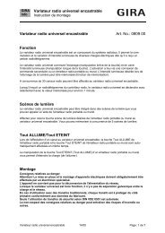
The room temperature controller supports the three control options "heating", "cooling" and "heating and cooling".<br />
In all three control options, the controller can work in different operating modes to which different setpoint<br />
temperatures are assigned. The following diagrams show these setpoint temperatures and their graduations.<br />
Comfort temp.<br />
= basic setpoint<br />
Standby temperature<br />
Night temp.<br />
Night temp.<br />
Standby temperature<br />
Comfort temp.<br />
Temperature<br />
Basic setpoint<br />
Comfort temp.<br />
Standby temperature<br />
Night temp.<br />
Comfort<br />
mode<br />
Temperature<br />
Comfort<br />
mode<br />
"Heating"<br />
Standby<br />
mode<br />
Standby<br />
heating<br />
temp. decrease<br />
Standby<br />
mode<br />
Standby<br />
cooling<br />
temp. increase<br />
Standby<br />
heating<br />
temp. decrease<br />
Night<br />
mode<br />
Night<br />
heating<br />
temp. decrease<br />
Night<br />
mode<br />
Night<br />
cooling<br />
temp. increase<br />
Night<br />
heating<br />
temp. decrease<br />
Frost/heat prot.<br />
mode<br />
Frost protection<br />
setpoint<br />
Night temp.<br />
Standby temp.<br />
Comfort temp.<br />
"Heating and cooling"<br />
Frost/heat prot.<br />
mode<br />
Heat protection<br />
setpoint<br />
Dead band between<br />
heating and cooling /<br />
symmetrical dead band<br />
Frost protection<br />
setpoint<br />
Night temp.<br />
Standby temp.<br />
Comfort temp.<br />
Comfort temp.<br />
= basic setpoint<br />
Standby temperature<br />
Night temp.<br />
Temperature<br />
Temperature<br />
Comfort<br />
mode<br />
Comfort<br />
mode<br />
"Cooling"<br />
Standby<br />
mode<br />
Standby<br />
cooling<br />
temp. increase<br />
Standby<br />
mode<br />
Standby<br />
cooling<br />
temp. increase<br />
Night<br />
cooling<br />
temp. increase<br />
Heat protection<br />
setpoint<br />
12/07 2100-xx/2101 xx Page 21/82<br />
Subject to change without notice<br />
Night<br />
mode<br />
Night<br />
mode<br />
Night<br />
cooling<br />
temp. increase<br />
Frost/heat prot.<br />
mode<br />
Frost/heat prot.<br />
mode<br />
Heat protection<br />
setpoint<br />
Dead band between<br />
heating and cooling /<br />
asymmetrical dead band<br />
Standby<br />
heating<br />
temp. decrease Night<br />
heating<br />
temp. decrease<br />
Frost protection<br />
setpoint
<strong>instabus</strong> <strong>KNX</strong>/<strong>EIB</strong> <strong>System</strong><br />
<strong>Sensor</strong><br />
Temperature control with additional stage considering as an example "heating and cooling" with symmetrical dead<br />
zone…<br />
Additional stage night temp.<br />
Additional stage standby temp.<br />
Additional stage comf. temp.<br />
Additional stage comf. temp.<br />
Additional stage standby temp.<br />
Additional stage night temp.<br />
Additional stage night temp.<br />
Basic stage standby temp.<br />
Basic stage comfort temp.<br />
Basic stage comfort temp.<br />
Basic setpoint<br />
Basic stage standby temp.<br />
Basic stage night temp.<br />
Temperature<br />
Comfort<br />
mode<br />
Standby<br />
mode<br />
SW<br />
Standby<br />
cooling<br />
temp. increase<br />
Standby<br />
heating<br />
temp. decr.<br />
Night<br />
cooling<br />
temp. increase<br />
Heat protection<br />
setpoint<br />
22/82 Page 2100-xx/2101 xx 12/07<br />
Subject to change without notice<br />
SW<br />
SW<br />
SW<br />
Night<br />
mode<br />
SW<br />
Night<br />
heating<br />
temp. decrease<br />
Frost/heat prot.<br />
mode<br />
Dead band between<br />
heating and cooling /<br />
symmetrical dead band<br />
SW<br />
Frost protection<br />
setpoint<br />
SW : Step width parameterized<br />
in the ETS plug-in<br />
If enabled in the ETS, 6 temperature setpoints can be varied in "heating and cooling" control option. Depending<br />
on the temperature decrease, increase or dead zone parameterized in the ETS, all temperature setpoints are<br />
derived from the basic setpoint temperature.<br />
It must be pointed out that changing the setpoint temperature for heating in the comfort mode will also change all<br />
other setpoint temperature values!<br />
The dead zone (temperature zone for which there is neither heating nor cooling) is the difference between the<br />
setpoint temperatures for "heating" and "cooling" in the comfort mode. The following applies:<br />
Tcomfort setpoint cooling – Tcomfort setpoint heating = Tdead zone; Tcomfort setpoint cooling ≥ Tcomfort setpoint heating<br />
Important notes:<br />
- If the dead zone is symmetrical, the basic setpoint is indirectly set via the comfort temperature for heating.<br />
- Changing the comfort setpoint temperature for cooling allows the adjustment of the dead zone. An<br />
adjustment of the dead zone with a symmetrical dead zone position will result in a shift of the comfort<br />
setpoint temperature for heating and thus of all other temperature setpoints. With an asymmetrical dead zone<br />
position, an adjustment of the comfort setpoint temperature for cooling will only shift the temperature<br />
setpoints for cooling. It is possible to shift the dead zone to 0 °C via local control (Tcomfort setpoint cooling = Tcomfort<br />
setpoint heating). In this case there is neither heating nor cooling, if the determined room temperature equals the<br />
comfort setpoint temperatures.<br />
The setpoint temperatures for "Standby" and "Night" are derived from the comfort setpoint temperatures for<br />
heating or cooling. The temperature increase (for cooling) and the temperature decrease (for heating) of both<br />
operating modes can be preset in the ETS.
<strong>instabus</strong> <strong>KNX</strong>/<strong>EIB</strong> <strong>System</strong><br />
<strong>Sensor</strong><br />
In this case, the standby or night setpoint temperatures will always shift together with the temperature<br />
increase/decrease resulting from the local control during the adjustment of the basic setpoint temperature or the<br />
dead zone. After the reprogramming with the ETS, the originally parameterized values can be accepted again.<br />
The following applies:<br />
Tstandby setpoint heating ≤ Tcomfort setpoint heating ≤ Tcomfort setpoint cooling ≤ Tstandby setpoint cooling<br />
12/07 2100-xx/2101 xx Page 23/82<br />
Subject to change without notice<br />
or<br />
Tnight setpoint heating ≤ Tcomfort setpoint heating ≤ Tcomfort setpoint cooling ≤ Tnight setpoint cooling<br />
In case of a two-stage control the setpoints of the additional stage are always derived dynamically from the<br />
setpoints of the basic stage. The temperature setpoints of the additional stage are predefined by the stage offset<br />
which is parameterized in the ETS. The stage offset cannot be adjusted in the local control mode.<br />
As far as a change of the basic setpoint temperature is concerned (when a new comfort setpoint temperature<br />
value for heating is being received by communication object no. 26), there basically two cases to be<br />
distinguished:<br />
- Case 1: The basic setpoint adjustment is permanently adopted,<br />
- Case 2: The basic setpoint adjustment is only temporarily adopted (default).<br />
Via the "Adopt basic temperature setpoint permanently" parameter on the "Room temperature controller function<br />
/setpoints" parameter page, it is possible to determine whether the changed basic temperature value shall be<br />
stored in memory permanently ("Yes") or only temporarily ("No").<br />
Case 1:<br />
If the basic temperature setpoint is changed, it will be permanently stored in the room temperature controller's<br />
EEPROM. The newly adjusted value will overwrite the basic temperature originally parameterized with the ETS!<br />
It should be noted, however, that frequent adjustments of the basic temperature (e.g. several times a day) can<br />
affect the product life of the device as the non-volatile memory is designed only for less frequent write access.<br />
Thus the basic setpoint received by the object remains in memory even after a bus voltage failure.<br />
Case 2:<br />
The basic setpoint received via the object stays only temporarily active in the current operating mode. In case of a<br />
bus voltage failure or following a switch-over into another operating mode (e.g. comfort followed by standby), the<br />
basic setpoint set via local control or received via the object will be discarded and replaced by the value which<br />
was originally parameterized in the ETS.<br />
Notes:<br />
- Since the setpoint temperatures for the "standby" and "night" operating modes or the setpoints for the "cooling"<br />
control option are derived - in consideration of the increase, decrease or dead zone values that are<br />
parameterized in the ETS - from the basic setpoint temperature for "heating", these setpoint temperatures will<br />
shift linearly by the change of the basic setpoint value.<br />
The temperature setpoints for the standby or night mode or "cooling" comfort mode (dead zone) will always be<br />
stored in the non-volatile EEPROM.<br />
- It has to be pointed out that temperature setpoints can only be changed or stored via the "Basic setpoint"<br />
object, if it was enabled in the ETS.
<strong>instabus</strong> <strong>KNX</strong>/<strong>EIB</strong> <strong>System</strong><br />
<strong>Sensor</strong><br />
2 Room temperature controller functions<br />
2.1 Operating modes<br />
The room temperature controller features several operating modes. By selecting theses modes it is possible to<br />
activate different temperature setpoints that, for example, depend on the presence of a person, the status of the<br />
heating or cooling system, the time of day or day of week.<br />
• Comfort mode:<br />
The comfort mode should be activated if people are present in the room that requires the room temperature to be<br />
adjusted to a comfortable and appropriate value. The switch-over into this operating mode can also take place via<br />
presence control.<br />
The comfort mode when activated is signalled by LED B ( ).<br />
• Standby mode<br />
If a room is not in use during the day as people are absent, the standby mode may be activated. This will set the<br />
room temperature to a standby value thus saving heating or cooling energy in the process.<br />
The standby mode when activated is signalled by LED C ( ).<br />
• Night mode<br />
During the night hours or during a longer absence it is often best to adjust the room temperature to cooler<br />
temperatures for heating systems (e.g. in bedrooms). In this case cooling systems can be adjusted to higher<br />
temperature values, if climate control is not required (e.g. in offices). For this purpose the night mode can be<br />
activated.<br />
The night mode when activated is signalled by LED D ( ).<br />
• Frost / heat protection mode<br />
Frost protection is necessary, if, for example, the room temperature must not fall below critical values when the<br />
window is open. Heat protection might be necessary, if the temperature in a mostly warm environment becomes<br />
too high due to external influences.<br />
In these cases a freezing or overheating of the room can be prevented by activating the frost/heat protection<br />
depending on the adjusted "heating" or "cooling" control option by specifying an individual temperature setpoint.<br />
A frost/heat protection when activated is signalled by LED H ( ).<br />
• Comfort mode extension (temporary comfort mode)<br />
The comfort mode extension is to be activated from the night mode or the frost/heat protection (not triggered by<br />
the "window state" object) and can be used to adjust the room temperature to the comfort temperature for a<br />
certain amount of time, if, for example the room 'is used' during the night as well. The extension is activated<br />
exclusively by a parameterized presence key. The comfort mode extension is automatically deactivated after a<br />
settable time has elapsed or by pressing the presence key again or via receiving a presence object value = "0".<br />
The extension cannot be retriggered.<br />
An individual temperature setpoint can be preset for each "heating" or "cooling" control option.<br />
24/82 Page 2100-xx/2101 xx 12/07<br />
Subject to change without notice
<strong>instabus</strong> <strong>KNX</strong>/<strong>EIB</strong> <strong>System</strong><br />
<strong>Sensor</strong><br />
2.1.1 Operating mode switch-over<br />
There are several ways to activate or switch-over the operating modes. Activating or switching-over –<br />
interdependent in terms of priority – are possible via…<br />
a) local operation of the presence key, if enabled,<br />
c) the 1-bit objects that are available separately for each operating mode or alternatively via the KONNEX objects<br />
(1 byte).<br />
Ad a):<br />
If the presence key has been selected for presence detection on parameter page "Controller functions", the<br />
presence key can be used to switch from the night mode or from the frost/heat protection mode over to the<br />
comfort mode for the preset comfort extension time on provision that the above modes have not been activated by<br />
the "Window state" object. The comfort mode extension is deactivated after this time has elapsed, after a new<br />
press on the presence key or after receiving a presence object value = "0". If the duration of the comfort extension<br />
is set to "0", the presence function can be activated, but the operating mode is not changed. During the comfort<br />
extension period, the comfort LED is lit up together with the "night mode" or the "frost/heat protection" LED.<br />
If the standby mode is active, it is possible to switch into the comfort mode by actuating the presence key or via a<br />
presence object value = "1".<br />
Ad b):<br />
One distinguishes whether the operating mode is to be switched-over via separate 1-bit objects or, alternatively,<br />
via the 1-byte KONNEX objects. The "Operating mode switch-over" parameter on the "Controller General"<br />
parameter page predefines how the switch-over will take place.<br />
• Operating mode switch-over via "switching (4 x 1 bit):<br />
There is a separate 1-bit switch-over object for each operating mode. Each one of these objects allows to switchover<br />
or to preset the current operating mode by priority.<br />
Taking into consideration the priority, the following switch-over hierarchy results from an operating mode switchover<br />
via the objects. One distinguishes between presence detection by presence key (table 1 / figure 1) and by<br />
presence detector (table 2 / figure 2 on next page):<br />
Table 1<br />
"Operating mode switch-over" objects:<br />
Obj.-No. 31<br />
Obj.-No. 28<br />
Obj.-No. 29<br />
Obj.-No. 30<br />
Window<br />
status<br />
Obj.-No. 34<br />
Presence<br />
key object<br />
Obj.-No. 33<br />
activated operating mode<br />
X X X X 1 X Frost /heat protection<br />
1 X X X 0 0 Frost /heat protection<br />
0 1 X X 0 0 Comfort<br />
0 0 1 X 0 0 Standby<br />
0 0 0 1 0 0 Night<br />
1 X X X 0 1 Comfort extension<br />
0 1 X X 0 1 Comfort<br />
0 0 1 X 0 1 Comfort<br />
0 0 0 1 0 1 Comfort extension<br />
0 0 0 0 0 0 last available mode<br />
0 0 0 0 0 1 Comfort / comfort mode<br />
extension *<br />
X = irrelevant<br />
*: depends on the last available operating mode.<br />
12/07 2100-xx/2101 xx Page 25/82<br />
Subject to change without notice
<strong>instabus</strong> <strong>KNX</strong>/<strong>EIB</strong> <strong>System</strong><br />
<strong>Sensor</strong><br />
Fig 1:<br />
Comfort prologation<br />
Frost/heat prot.<br />
Comfort<br />
Standby<br />
Comfort prolongation<br />
Night<br />
1<br />
0<br />
1<br />
0<br />
1<br />
0<br />
Comfort<br />
Local presence key/<br />
precence object<br />
Table 2<br />
"Operating mode switch-over" objects:<br />
Obj.-No. 31<br />
Obj.-No. 28<br />
Obj.-No. 29<br />
Obj.-No. 30<br />
Frost/heat prot.<br />
Switch-over objects/<br />
local operation/<br />
operating mode after reset<br />
Window<br />
status<br />
Obj.-No. 34<br />
Presence<br />
detector<br />
object<br />
Obj.-No. 33<br />
26/82 Page 2100-xx/2101 xx 12/07<br />
Subject to change without notice<br />
1<br />
0<br />
Window status<br />
object 34<br />
(possibly delayed)<br />
activated operating mode<br />
X X X X 1 X Frost /heat protection<br />
X X X X 0 1 Comfort<br />
1 X X X 0 0 Frost /heat protection<br />
0 1 X X 0 0 Comfort<br />
0 0 1 X 0 0 Standby<br />
0 0 0 1 0 0 Night<br />
0 0 0 0 0 0 last available mode<br />
X = irrelevant<br />
Fig 2:<br />
Frost/heat prot.<br />
Comfort<br />
Standby<br />
Night<br />
Switch-over objects/<br />
local operation/<br />
operating mode after reset<br />
Frost/heat protection<br />
Comfort<br />
1<br />
1<br />
0<br />
0<br />
Window status<br />
Presence detector object object 34<br />
object 33 (possibly delayed)<br />
Operating mode<br />
Operating mode
Notes on operating mode switch-over via "Switching" (4 x 1-bit):<br />
<strong>instabus</strong> <strong>KNX</strong>/<strong>EIB</strong> <strong>System</strong><br />
<strong>Sensor</strong><br />
• When the operating modes are switched-over, the objects, too, (comfort mode / standby mode / night mode /<br />
frost/heat protection) will always be updated and can, if applicable, be read out (set "read" flag!). Once the<br />
"transmission" flag is set for these objects, changed values will also be actively transmitted to the bus. Following<br />
a return of bus voltage or an initialization, the object corresponding to the set operating mode will be updated<br />
and its value actively transmitted to the bus when the "transmission" flag is set.<br />
• When parameterizing a presence key:<br />
The presence object is active "1") for the duration of an activated comfort mode extension.<br />
The presence object will be automatically deleted ("0"), if the comfort mode extension is terminated after the<br />
extension time has elapsed or if the operating mode has been switched by a higher-priority control via the<br />
switch-over objects or via local operation.<br />
• The operating mode switch-over via "value" (2 x 1-byte):<br />
A shared 1-bit switch-over object exists for all operating modes. Via this value object, the operating mode can<br />
instantly be switched over after receiving only one telegram. The received value will determine the operating<br />
mode.<br />
In addition, there is a second 1-byte object available which can (by forced control and higher ranking) set an<br />
operating mode independent of all other available switch-overs. Both 1-byte objects are implemented according to<br />
the KONNEX specification.<br />
Taking into account the priorities there is the following switching hierarchy for an operating mode switch-over by<br />
objects, with a distinction being made between a presence detection via presence key (table 1 / figure 1) and by<br />
presence detector (table 2 / figure 2 on next page):<br />
Table 1<br />
"Operating mode<br />
switch-over" object<br />
"Forced object<br />
operating mode"<br />
object ***<br />
Obj.-No. 28 Obj.-No. 32<br />
Window<br />
status<br />
Obj.-No. 34<br />
Presence<br />
key object<br />
Obj.-No. 33<br />
activated operating mode<br />
X 01 X X Comfort<br />
X 02 X X Standby<br />
X 03 X X Night<br />
X 04 X X Frost /heat protection<br />
X 00 1 X Frost /heat protection<br />
01 00 0 0 Comfort<br />
02 00 0 0 Standby<br />
03 00 0 0 Night<br />
04 00 0 0 Frost /heat protection<br />
01 00 0 1 Comfort<br />
02 00 0 1 Comfort<br />
03 00 0 1 Comfort extension<br />
04 00 0 1 Comfort extension<br />
00 00 0 0 last available mode<br />
00 00 0 1 Comfort / comfort mode<br />
extension *<br />
*: depends on the last available operating mode. / X = irrelevant<br />
**: Values greater than "04" will not be evaluated. A "00" value will leave the last available operating mode<br />
active.<br />
***: Values greater than "04" will not be evaluated. A "00" value signifies a deactivated forced object.<br />
12/07 2100-xx/2101 xx Page 27/82<br />
Subject to change without notice
<strong>instabus</strong> <strong>KNX</strong>/<strong>EIB</strong> <strong>System</strong><br />
<strong>Sensor</strong><br />
Fig 1:<br />
Comfort<br />
Standby<br />
Comf. prolongation<br />
Night<br />
Comf. prolongation<br />
Frost/heat prot.<br />
Table 2<br />
"Operating mode<br />
switch-over" object<br />
1<br />
0<br />
1<br />
0<br />
1<br />
0<br />
Local presence key/<br />
presence object<br />
Comfort<br />
"Forced-control<br />
object operating<br />
mode" object ***<br />
Obj.-No. 28 Obj.-No. 32<br />
"01"<br />
"02"<br />
"03"<br />
"04"<br />
Frost/heat protection<br />
KONNEX switch-over object/<br />
local operation/<br />
operating mode after reset<br />
Window<br />
status<br />
Obj.-No. 34<br />
28/82 Page 2100-xx/2101 xx 12/07<br />
Subject to change without notice<br />
1<br />
0<br />
Window status<br />
object 34<br />
(poss. delayed)<br />
Comfort<br />
Standby<br />
Night<br />
Frost/heat prot.<br />
Presence<br />
detector<br />
object<br />
Obj.-No. 33<br />
deactivated "00"<br />
"01"<br />
"02"<br />
"03"<br />
"04"<br />
Operat. mode<br />
KONNEX constraint object<br />
activated operating mode<br />
X 01 X X Comfort<br />
X 02 X X Standby<br />
X 03 X X Night<br />
X 04 X X Frost /heat protection<br />
X 00 1 X Frost /heat protection<br />
X 00 0 1 Comfort<br />
01 00 0 0 Comfort<br />
02 00 0 0 Standby<br />
03 00 0 0 Night<br />
04 00 0 0 Frost /heat protection<br />
00 00 0 0 last available mode<br />
X = irrelevant<br />
**: Values greater than "04" will not be evaluated. A "00" value will leave the last available operating mode<br />
active.<br />
***: Values greater than "04" will not be evaluated. A "00" value signifies a deactivated forced object.
Fig 2:<br />
Comfort<br />
Standby<br />
Night<br />
Frost/heat prot.<br />
"01"<br />
"02"<br />
"03"<br />
"04"<br />
KONNEX switch-over object/<br />
local operation/<br />
operating mode after reset<br />
Frost/heat protection<br />
1<br />
Comfort<br />
0<br />
1<br />
Window status<br />
object 34<br />
0<br />
(poss. delayed)<br />
Presence detector object<br />
object 33<br />
Comfort<br />
Standby<br />
Night<br />
Frost/heat protection<br />
Notes for operating mode switch-over via "switching" (2 x 1-byte):<br />
<strong>instabus</strong> <strong>KNX</strong>/<strong>EIB</strong> <strong>System</strong><br />
<strong>Sensor</strong><br />
deactivated "00"<br />
Operat. mode<br />
KONNEX constraint object<br />
• Any operating mode switch-over will also update the KONNEX switch-over object and can be, if applicable, read<br />
out (set "read" flag!). If the "transmission" flag is set with this object, the current value will actively transmitted to<br />
the bus following a change. After a return of bus voltage or an initialization, the value corresponding to the<br />
adjusted operating mode will be actively transmitted on the bus if flag is set to "transmission". In case controller<br />
extensions are used, the "transmission" flag must also be set!<br />
• When parameterizing a presence key:<br />
The presence object is active ("1") for the duration of an activated comfort mode extension.<br />
The presence object will automatically be deleted ("0"), if the comfort mode extension is terminated after the<br />
elapsed extension time, if the operating mode has been switched by a higher-priority control via the switch-over<br />
objects or local operation or if a forced operating mode has been deactivated via the KONNEX forced-control<br />
object (forced-control object � "00").<br />
12/07 2100-xx/2101 xx Page 29/82<br />
Subject to change without notice<br />
"01"<br />
"02"<br />
"03"<br />
"04"
<strong>instabus</strong> <strong>KNX</strong>/<strong>EIB</strong> <strong>System</strong><br />
<strong>Sensor</strong><br />
2.1.2 Notes on the operating modes<br />
Presence function / comfort mode extension:<br />
Via a presence detection the room temperature controller can switch into the comfort mode extension for a short<br />
time when a key is pressed or into the comfort mode if movement is detected. The "Presence detection" and<br />
"Type of presence detection" parameters on the "Room temperature controller function – functions" parameter<br />
page determine whether the presence detection is controlled by movement via the presence detector or manually<br />
by pressing the presence key:<br />
• Presence detection via presence key:<br />
If the presence key is enabled as the type of presence detection, the setting "=Presence key" can be selected<br />
under key functions. In addition, the "Presence object" object 33 is enabled.<br />
That way, it is possible to switch into the comfort mode extension during activated night mode or frost/heat<br />
protection (not activated via the "window status" object) by actuating the presence key or via a presence object<br />
value = "1". The extension is automatically deactivated as soon as the parameterized "Duration of comfort mode<br />
extension" has elapsed. A comfort mode extension can be prematurely deactivated, if the presence key is<br />
pressed again or if a value = "0" is received by the object. Retriggering of the extension time is not possible.<br />
If the duration of the comfort mode extension is set to "0", it will not be possible to activate a comfort mode<br />
extension from the night mode or the frost/heat protection. In this case, the operating mode is not changed even<br />
though the presence function is activated.<br />
If the standby mode is active, it is possible to switch into the comfort mode by actuating the presence key or via<br />
a presence object value = "1". This will also be the case, if the duration of the comfort mode extension is<br />
parameterized to "0". The active mode remains active for as long as the presence function is activated or until<br />
there is another operating mode.<br />
The presence object or the presence function will always be deleted when switching over into another operating<br />
mode or after a forced-control operating mode has been deactivated (with KONNEX forced-control switch-over).<br />
The presence object is bi-directional ("W" and "T" flags set to default) so that an activation (= "1") or a<br />
deactivation (= "0") of the presence function will result in a transmission of telegrams with the corresponding<br />
object value. A presence function including the object that was activated before a reset will always be deleted<br />
after the reset.<br />
• Presence detection by the presence detector:<br />
If a presence detector is enabled for presence detection purposes, only the "Presence object" object 33 will be<br />
visible. This object can be used to incorporate presence detectors in the room temperature control.<br />
If any movement is detected ("1" telegram), the controller will switch into the comfort mode. The presettings by<br />
the switch-over objects or via local control directly on the touch sensor itself are not relevant. Only a window<br />
contact or the KONNEX forced-control object have a higher priority.<br />
After the delay time in the presence detector has elapsed ("0" telegram), the controller switches back into the<br />
mode which was active before the presence detection or it will track the telegrams of the switch-over objects<br />
received during the presence detection.<br />
Switching-over of the operating mode on the room temperature controller is not possible while the presence<br />
detection is active.<br />
A presence function that was activated before a reset will always be deleted after the reset. In this case the<br />
presence detector has to transmit a new "1" telegram in order to activate the presence function.<br />
30/82 Page 2100-xx/2101 xx 12/07<br />
Subject to change without notice
<strong>instabus</strong> <strong>KNX</strong>/<strong>EIB</strong> <strong>System</strong><br />
<strong>Sensor</strong><br />
Window status:<br />
The room temperature controller provides different ways of switching into the frost/heat protection . Besides<br />
switching by means of the corresponding operating mode switch-over object, the frost/heat protection can be<br />
activated by a window contact. Among these options, the window contact has the higher priority.<br />
A telegram with the value = "1" (opened window) to object 34 will activate the frost/heat protection. In this case<br />
the operating mode cannot be deactivated by the operating mode switch-over objects (with the exception of the<br />
KONNEX forced-control object).<br />
Only a telegram with the value = "0" (closed window) will reset the window status and deactivate the frost/heat<br />
protection. Subsequently, the operating mode that was set before the opening of the window or tracked via the<br />
bus during the time the window was open will be activated.<br />
Operating mode after reset:<br />
In the ETS it is possible to determine via the "Operating mode after reset" parameter on the "Controller General"<br />
parameter page which operating mode is to be activated following a return of bus voltage or a programming<br />
operation with the ETS. The following settings are possible:<br />
- "Comfort mode": After the initialization phase the comfort mode is activated.<br />
- "Standby mode": After the initialization phase the standby mode is activated.<br />
- "Night mode": After the initialization phase the night mode is activated.<br />
- "Frost/heat protection": After the initialization phase the frost/heat protection is activated.<br />
- Restore operating mode before reset": The mode that was activated before a reset will be readjusted<br />
after the initialization phase of the device.<br />
The objects associated with the activated operating mode will be updated after a reset.<br />
Notes on the setting "Restoring operating mode before reset":<br />
• Frequent adjustments of the operating mode during ongoing operation (e.g. several times a day) may affect the<br />
product life of the device as the non-volatile storage (EEPROM) is designed only for less frequent write access.<br />
• A presence function including the object that was activated before a reset is deleted after the reset. The<br />
operating mode activated by the presence function, however, remains active after the reset.<br />
A comfort mode extension which was restarted by a reset is automatically deactivated after the extension time<br />
has elapsed.<br />
The "window status" object is deleted after a reset ("0"). In this case, too, the frost/heat protection which was<br />
previously activated via the window status remains activated even after a reset.<br />
12/07 2100-xx/2101 xx Page 31/82<br />
Subject to change without notice
<strong>instabus</strong> <strong>KNX</strong>/<strong>EIB</strong> <strong>System</strong><br />
<strong>Sensor</strong><br />
2.1.3 Controller status<br />
The room temperature controller is able to transmit its status. Available is either a general collective status report<br />
(1-byte) or alternatively one of up to 8 individual status reports (1-bit).<br />
The "Status controller" parameter on the "Actuating variable and status output" parameter page releases the<br />
status report and determines the status format:<br />
• "Status controller" = "controller general":<br />
The 1-byte status object 36 includes the complete status information. The status - controlled by the control<br />
algorithm – is actively transmitted (cyclically every 30 seconds) to the bus (pre-condition: "T" flag is set!)The<br />
setting of the “R” flag allows the read-out of the status.<br />
Settings Relevance of data<br />
Controller general<br />
1-byte<br />
• "Status controller" = "Transmit individual status":<br />
Bit 0: 1: comfort mode active<br />
Bit 1: 1: standby mode active<br />
Bit 2: 1: night mode active<br />
Bit 3: 1: frost/heat protection active<br />
Bit 4: 1: controller disabled<br />
Bit 5: 1: heating; 0: cooling<br />
Bit 6: 1: controller inactive (dead zone)<br />
Bit 7: 1: frost alarm (T room ≤ + 5 °C)<br />
The 1-bit status object 36 includes the status information selected by the "Individual status" parameter. The status<br />
- controlled by the control algorithm – is actively transmitted (cyclically every 30 seconds) to the bus (precondition:<br />
"T" flag is set!)). The setting of the "R" flag allows the read-out of the status.<br />
Parameterization for<br />
"Individual status"<br />
Relevance of data<br />
Comfort mode active 1: comfort mode / extension active 0: no comfort mode<br />
Standby mode active 1: standby mode active 0: no standby mode<br />
Night mode active 1: Night mode active 0: no night mode<br />
Frost/ heat protection active 1: frost/heat protection active 0: no frost/heat protection<br />
Controller disabled 1: controller disabled (dew-point mode) 0: controller not disabled<br />
Heating/cooling 1: heating operation 0: cooling operation<br />
Controller inactive 1: controller inactive (dead zone) 0: controller active<br />
Frost alarm 1: frost alarm (T room ≤ + 5 °C) 0: no frost alarm (T room > + 5 °C)<br />
Meaning of status reports:<br />
• Comfort operation: Active if the operating mode "comfort ' '" or a comfort mode extension<br />
" " or " " is activated.<br />
• Standby operation: active if the "standby ' '" operating mode is activated.<br />
• Night-time operation: active if the "night-time ' '" operating mode is activated.<br />
• Frost/ heat protection: active if the "frost/heat protection ' '" operating mode is activated.<br />
• Controller disabled: active if controller disable is activated (dew-point mode).<br />
• Heating/cooling: active if the heating mode is activated and inactive if cooling mode is activated. (inactive<br />
with controller disabled.)<br />
• Controller inactive: active with the "heating and cooling" control option when the measured room temperature<br />
lies within the dead zone. This status information is always "0" for the individual "heating"<br />
or "cooling" control options! (inactive if controller is disabled.)<br />
• Frost alarm: active if the detected room temperature reaches or drops below + 5 °C. The status report<br />
has no significant influence on the controller behaviour.<br />
The status object 36 will be updated following a reset after the initialization phase. Afterwards the status is<br />
updated every 30 seconds parallel to the calculation of the controller’s actuating variable.<br />
32/82 Page 2100-xx/2101 xx 12/07<br />
Subject to change without notice
<strong>instabus</strong> <strong>KNX</strong>/<strong>EIB</strong> <strong>System</strong><br />
<strong>Sensor</strong><br />
2.1.4 Additional controller status<br />
The additional controller status is an object in which information already available on the bus is to be collected so<br />
that it can be displayed with a suitable device. This 1-byte object is a mere visualization object which does not<br />
allow any write access. This status object possesses a <strong>KNX</strong>-certified (but not standardized) datapoint type.<br />
Settings for "Controller<br />
general"<br />
Relevance of data for "Additional controller status report"<br />
Bit 0 1: normal operating mode 0: forced-control operating mode<br />
Bit 1 1: comfort extension active 0: no comfort extension<br />
Bit 2 1: presence (presence detector) 0: no presence (presence detector)<br />
Bit 3 1: presence (presence key) 0: no presence (presence key)<br />
Bit 4 1: window contact active 0: no window opened<br />
Bit 5 1: additional stage active 0: additional stage not active<br />
Bit 6 1: heat protection active<br />
0: no heat protection<br />
(heat protection temp. < actual (heat protection temp. > actual<br />
temp.)<br />
temp.)<br />
Bit 7 1: controller disabled (dew-point mode) 0: controller not disabled<br />
The status object 57 will be updated following a reset after the initialization phase. Thereafter, the additional<br />
controller status is updated every 30 seconds parallel to the computation of the actuating variable of the controller.<br />
In the event of a change, the new status determined will be transmitted to the <strong>EIB</strong>.<br />
12/07 2100-xx/2101 xx Page 33/82<br />
Subject to change without notice
<strong>instabus</strong> <strong>KNX</strong>/<strong>EIB</strong> <strong>System</strong><br />
<strong>Sensor</strong><br />
2.2 Control options and control option switch-over<br />
The room temperature controller features up to two control options. These control options determine whether the<br />
controller shall address heating systems (individual control option "heating") or cooling systems (individual control<br />
option "cooling") via its actuating variable. It is also possible to activate a mixed-mode in which the controller can<br />
switch-over automatically or, alternatively, object-controlled between "heating" and "cooling".<br />
Moreover, the control operation can be carried out in two stages for addressing an additional heating and cooling<br />
device. If controlled in two stages, actuating variables will be calculated separately for the basic and additional<br />
stage and transmitted on the bus depending on the deviation between actual and setpoint temperature.<br />
The "Control option" parameter on the "Controller General" parameter page determines the control option to be<br />
carried out and activates, if applicable, the additional stage(s).<br />
For the individual control options "heating" or "cooling" without additional stage, the controller runs with only one<br />
actuating variable. Alternatively, it runs with two actuating variables for the parameterized control option, if the<br />
additional stage is activated. Depending on the determined room temperature and the preset setpoint<br />
temperatures of the operating modes, the room temperature controller decides independently whether heating or<br />
cooling energy is required and calculates the actuating variable for the heating or cooling system.<br />
Following a reset (return of bus voltage or new ETS programming) in the "heating" or "cooling" mode, the<br />
controller will always operate in the control option that was set in the ETS.<br />
In the "heating and cooling" mixed-mode the controller is able to address heating and cooling systems. In this<br />
case, the switch-over behaviour of the control options can be preset:<br />
• The "Switching-over between heating and cooling" parameter on parameter page "Controller functions" is set<br />
to "automatic":<br />
Depending on the determined room temperature and the preset basic temperature setpoint value or the dead<br />
zone, the heating or cooling mode is automatically activated . If the room temperature lies within the preset<br />
dead zone, neither heating nor cooling will take place (both actuating variables = "0"). The room will be cooled<br />
down if the room temperature is higher than the temperature setpoint for cooling. The room will be heated up,<br />
if the room temperature is lower than the temperature setpoint for heating.<br />
With an automatic switch-over of the control option, the information can be actively transmitted to the bus via<br />
the "Control option switch-over" object 35. The "Automatic transmission heating/cooling switch-over"<br />
parameter determines when a control option switch-over is transmitted.<br />
- Setting "Changing the control option":<br />
In this case, a telegram is transmitted solely when switching-over from heating to cooling (object value = "0")<br />
or from cooling to heating (object value = "1).<br />
- Setting "Changing the output variable":<br />
With this setting, the current control option will always be transmitted if the output variable has changed. With<br />
the actuating variable = "0" the control option that was last active will be transmitted.<br />
If the determined room temperature lies within the dead zone, the control option last activated will be retained<br />
in the object value until the controller is switched-over into the other control option.<br />
With an automatic switch-over, the object value can also be transmitted cyclically. The "Cyclical<br />
heating/cooling switch-over" parameter enables cyclical transmission (factor setting > "0") and determines the<br />
cycle time.<br />
Notes on the automatic switch-over of the control option:<br />
A dead zone that is too narrow might result in continuous switching over between heating and cooling. For this<br />
reason the dead zone (temperature difference between the set-temperatures for heating and cooling comfort<br />
mode) should preferably not be adjusted below the default value.<br />
34/82 Page 2100-xx/2101 xx 12/07<br />
Subject to change without notice
<strong>instabus</strong> <strong>KNX</strong>/<strong>EIB</strong> <strong>System</strong><br />
<strong>Sensor</strong><br />
• The "Switching-over between heating and cooling" parameter on parameter page "Controller functions" is set<br />
to "via object":<br />
Independent of the dead zone, the control option is then controlled via the "Control option switch-over" object<br />
35. This type of switch-over may be required, for example, in case of heating and cooling via a single-duct<br />
system (combined heating and cooling system). For this purpose, the temperature of the medium in the singleduct<br />
system must be changed beforehand by the system control. Afterwards, the control option is set via the<br />
object (often the single-duct system uses cold water for cooling during the summer, hot water for heating<br />
during the winter).<br />
The "Control option switch-over" object has the following polarity: "1": heating; "0": cooling. After a reset, the<br />
object value "0" and the "Control option heating/ cooling after reset" parameter will be activated.<br />
The "Control option heating / cooling after reset" parameter determines which control option will be activated<br />
after a reset. The "heating" or "cooling" setting causes the controller to activate the parameterized control<br />
option directly after the initialization phase. Setting the "Control option before reset" parameter will activate the<br />
control option that was selected before the reset.<br />
If a switch-over takes place via the control option object, the controller will first switch-over into a control option<br />
that was set after the reset. The controller will switch-over, if applicable, into the other control option only after<br />
the device has received an object update.<br />
Notes on the "control option before reset" setting:<br />
• Frequent adjustments of the control options during ongoing operation (e.g. several times a day) may affect<br />
the product life of the device as in this case the non-volatile storage (EEPROM) is only designed for less<br />
frequent write access.<br />
Heating / cooling message:<br />
Depending on the selected control option it is possible to output the information via separate objects whether<br />
heating or cooling energy is currently required, i.e. whether heating or cooling operation is in progress.<br />
As long as the actuating variable for heating (cooling) is > "0", a "1" telegram is transmitted via the "heating"<br />
("cooling") signalling object. The message telegrams will be reset only if the actuating variables = "0" ("0"<br />
telegram will be transmitted).<br />
Exception: In case of a 2-state control, the LEDs "heating" or "cooling" will light up or the signalling objects for<br />
heating and cooling will already become active as soon as the temperature falls short of the temperature setpoint<br />
in case of heating or exceeds the temperature setpoint in case of cooling. In this case, the parameterized<br />
hysteresis is not being considered.<br />
Heating and cooling at the same time is not possible!<br />
The signalling objects may be enabled via the "Heating message" or the "Cooling message" parameter on the<br />
"Actuating variable and status output" parameter page.<br />
The signalling objects are controlled by the control algorithm. It has to be considered that the actuating variable is<br />
calculated only every 30 seconds (thus updating the signalling objects every 30 seconds).<br />
12/07 2100-xx/2101 xx Page 35/82<br />
Subject to change without notice
<strong>instabus</strong> <strong>KNX</strong>/<strong>EIB</strong> <strong>System</strong><br />
<strong>Sensor</strong><br />
2.3 Room temperature control and actuating variables<br />
2.3.1 Control algorithms, control circuits and calculation of actuating variable<br />
A comfortable temperature control for a living space requires a special control algorithm which controls the<br />
installed heating or cooling systems. By considering the setpoint temperatures as well as the actual room<br />
temperature, the controller determines the actuating variables controlling the heating or cooling system.<br />
The control system (control circuit) consists of the room temperature controller, the servo drive or the switching<br />
actuator (for the use of electro-thermal drives), the actual heating or cooling element (e.g. heaters or cooling<br />
ceiling) and the room. This results in the following control process:<br />
Set value<br />
temperature<br />
+<br />
Room temp. controller<br />
-<br />
Control<br />
algorithm<br />
Actuator/<br />
ETA<br />
Radiator/<br />
cooling<br />
ceiling<br />
Sun radiation,<br />
outside temperature, ...<br />
Room<br />
temperature<br />
The controller measures the actual temperature (determined room temperature) and compares it with the given<br />
setpoint temperature. The control algorithm calculates the actuating variable from the difference between actual<br />
and setpoint temperature. This enables the controller to compensate for actual/setpoint temperature differences in<br />
the control circuit caused by external influences (e.g. strong exposure to sun or varying outside temperatures) by<br />
regularly readjusting the actuating variable. In addition, the flow temperature of the heating and cooling circuit<br />
affects the control process making it necessary to adapt the actuating variables.<br />
The room temperature controller allows the option between a continuous or switching proportional/integral control<br />
(PI) or a switching 2-state control.<br />
36/82 Page 2100-xx/2101 xx 12/07<br />
Subject to change without notice<br />
Room
<strong>instabus</strong> <strong>KNX</strong>/<strong>EIB</strong> <strong>System</strong><br />
<strong>Sensor</strong><br />
The actuating variables calculated by the control algorithm are output via the "Actuating variable heating" or<br />
"Actuating variable cooling" communication objects. The control algorithm selected for the heating and/or cooling<br />
operation determines, among other things, also the format of the actuating variable object. Thus, it is possible to<br />
create 1-bit or 1-byte actuating variable objects.<br />
The control algorithm is determined via the "Type of heating control" or "Type of cooling control" parameters on<br />
the "Controller general" parameter page, possibly also for the additional stages.<br />
Each of the following three algorithms can be selected:<br />
1. <strong>Continuous</strong> PI control:<br />
A PI control is an algorithm consisting of a proportional and an integral part. A combination of these control<br />
characteristics allows to accurately adjust the room temperature as fast as possible without or with only small<br />
control deviations.<br />
This algorithm lets the room temperature controller calculate a new continuous actuating variable periodically<br />
every 30 seconds. This one will be output to the bus via a 1-byte value object, if the calculated actuating variable<br />
has changed by a predetermined percentage. The "Automatic transmission if value changes by..." parameter on<br />
the "Actuating variable and status output" parameter page determines the change interval in percent.<br />
Variable (0 ... 100 %)<br />
Integral part<br />
Proportional part<br />
12/07 2100-xx/2101 xx Page 37/82<br />
Subject to change without notice<br />
Time<br />
An additional PI controlled heating or cooling stage works exactly as the PI control of the basic stage. The<br />
difference is that the setpoint will shift by taking into account the parameterized stage offset.<br />
Characteristic feature of the PI control:<br />
If the setpoint/actual value deviation of the room temperature results in an actuating variable of 100%, the room<br />
temperature controller uses the maximum actuating variable until the determined room temperature reaches the<br />
setpoint. This special control behaviour is known as 'clipping'.<br />
This will quickly heat up or cool down the temperature in chilled or overheated rooms. In two stage heating or<br />
cooling systems, this control behaviour also applies to the actuating variables of the additional stages.
<strong>instabus</strong> <strong>KNX</strong>/<strong>EIB</strong> <strong>System</strong><br />
<strong>Sensor</strong><br />
2. Switching PI control:<br />
This parameterization will also keep the room temperature constant via the PI control algorithm. Averaged over<br />
time, the control system will behave the same as with a continuous controller. The only difference compared to a<br />
continuous control is the actuating variable output.<br />
The actuating variable calculated periodically every 30 seconds by the algorithm is internally converted into an<br />
equivalent pulse width modulated (PWM) actuating variable signal and output to the bus via a 1-bit switching<br />
object after the cycle time.<br />
Allowing for the cycle time which is adjustable via the "Cycle time of the switching actuating variable..." parameter<br />
on the "Actuating variable and status output" parameter page, the average value of the actuating variable signal<br />
resulting from this modulation is a measure for the averaged valve position of the control valve thus making it a<br />
reference value for the adjusted room temperature.<br />
Shifting of the average value and thus changing of the heating output is achieved by changing the pulse/pause<br />
ratio of the actuating variable signal.<br />
Depending on the calculated actuating variable, the controller adapts the pulse/pause ratio only at the end of a<br />
time period! Each change in the actuating variable is realized no matter what the relative change of the actuating<br />
variable is (the "Automatic transmission if value changes by..." and "Cycle time for automatic transmission..."<br />
parameters have no function here). The actuating variable last calculated within an active time period will be<br />
realized. If the setpoint temperature changes, for example, due to switching-over into another operating mode, the<br />
actuating variable will also be adapted only at the end of an active cycle time.<br />
The following figure shows the output actuating variable switching signal depending on the actuating variable<br />
internally calculated (first 30 %, then 50 % actuating variable; actuating variable output not inverted).<br />
Variable<br />
ON<br />
OFF<br />
No new variable calculated since<br />
the beginning of the last cycle time.<br />
Previous variable will be kept.<br />
30 % 70 % 30 % 70 % 50 % 50 %<br />
Cycle time<br />
e. g. 15 min.<br />
Variable (steady value) =<br />
New variable 50 %<br />
calculated and reset.<br />
a<br />
a + b<br />
With an actuating variable of 0 % (continuously switched-off) or 100 % (continuously switched-on) an actuating<br />
variable telegram according to the actuating variable value ("0" or "1") is output after a cycle time has elapsed.<br />
With this type of control, the 'clipping' behaviour (cf. "continuous PI control") is active as well.<br />
Even in case of a switching PI control, the controller always calculates internally with continuous actuating<br />
variable values. These continuous values can be additionally output to the bus via a separate 1-byte value object,<br />
for example, to display it as status information.<br />
With a switching PI control (PWM), the value object 46 is created for heating and the value object 48 for cooling. If<br />
additional stages are used, the value object 47 will be additionally enabled for the additional heating and the value<br />
object 49 for the additional cooling.<br />
If the actuating variable for heating and cooling is to be output via a shared object, the continuous value for the<br />
activated control option will be transmitted via the object 46 and, if applicable, for the additional stages via the<br />
object 47.<br />
The status value objects are only updated after the elapse of the parameterized cycle time together with the<br />
actuating output. The "Automatic transmission if value changes by..." and "cycle time for automatic<br />
transmission..." parameters have no function here.<br />
An additional PI controlled heating or cooling stage works exactly the same as the switching PI control of the<br />
basic stage. The difference is that the setpoint will shift by taking into account the parameterized stage offset. All<br />
PWM controls use the same cycle time.<br />
38/82 Page 2100-xx/2101 xx 12/07<br />
Subject to change without notice<br />
Time
<strong>instabus</strong> <strong>KNX</strong>/<strong>EIB</strong> <strong>System</strong><br />
<strong>Sensor</strong><br />
Cycle time:<br />
In most cases, the pulse width modulated actuating variables are used to control electro-thermal drives. The room<br />
temperature controller transmits the switching actuating variable telegrams to a switching actuator (preferably with<br />
semi-conductor switching elements) which is connected to the drives.<br />
Setting the cycle time for the PWM signal allows to adapt the control to the drives that are being used. The cycle<br />
time determines the switching frequency of the pulse modulated signal and allows the adaptation to the adjusting<br />
cycle times of the servo drive (traversing time the drive requires to adjust the valve from a completely closed<br />
position to a completely opened position). In addition to the adjusting cycle time the dead time (time during which<br />
the servo drives show no response when switching on or off) has to be considered. If different drives with different<br />
adjusting cycle times are used, the longer time is to be considered. The manufacturer’s specifications for the drive<br />
have to be observed.<br />
Two cases for the adjustment of the cycle time can be considered:<br />
I. Cycle time 2 x adjusting cycle time of the drives being used, for example 15 minutes (default)<br />
In this case, the pulse/pause times of the PWM signal are long enough for the drives to completely open or<br />
close within a time period.<br />
Advantages:<br />
The desired average value for the actuating variable and thus the required room temperature is relatively<br />
accurately adjusted even with several drives that are simultaneously activated.<br />
Disadvantages:<br />
It has to be considered that - due to the constantly 'travelled' full valve lift - the product life of the drives may<br />
decrease. The heat transfer to the room in the vicinity of the heater may be non-uniform and may be felt<br />
bothering to some people if the cycle times are very long ( > 15 minutes) and if the system has a slower<br />
response (for example in case of smaller hot water heaters).<br />
Notes:<br />
• This setting for the cycle time is recommended for slower, more inert heating systems (for example<br />
underfloor heating).<br />
• This setting is also recommended for a larger number of possibly different drives making it easier to average<br />
the valve travel.<br />
II. Cycle time > adjusting cycle time of the drives being used, for example 2 minutes (default)<br />
In this case, the short pulse/pause times of the PWM signal are not sufficient for the drives to completely open<br />
or close within a time period.<br />
Advantages:<br />
This setting ensures a constant water flow through the heaters with a uniform heat transfer to the room.<br />
If only one servo drive is controlled, the controller is able to compensate for the shift of the average value<br />
caused by the short cycle time by continuously adapting the actuating variable and is thus able to adjust the<br />
desired room temperature.<br />
Disadvantages:<br />
If more than one drive is controlled at the same time, the desired average for the actuating variable and thus<br />
the required room temperature is adjusted only very poorly or with larger deviations.<br />
Important:<br />
• This setting for the cycle time is recommended for fast-responding heating systems (for example hot water<br />
heaters with higher flow temperature).<br />
12/07 2100-xx/2101 xx Page 39/82<br />
Subject to change without notice
<strong>instabus</strong> <strong>KNX</strong>/<strong>EIB</strong> <strong>System</strong><br />
<strong>Sensor</strong><br />
3. Switching 2-state control:<br />
The 2-state control represents a very simple temperature control. For this type of control, two hysteresis<br />
temperature values are predefined. The controller addresses the actuating elements via switch-on and switchoff<br />
actuating variable commands (1-bit). A continuous actuating variable will not be calculated with this type of<br />
control. The room temperature is evaluated periodically every 30 seconds as well, i.e. the actuating variables, if<br />
required, will change only during these times.<br />
While the 2-state temperature control is very simple, the fluctuating temperature is a disadvantage. For this<br />
reason, no fast responding heating or cooling systems should be controlled via a 2-state control as it may result<br />
in very strong temperature overshoot and thus in a loss of comfort.<br />
When defining the hysteresis limit settings, one has to distinguish between the control options:<br />
• Individual control options "heating" or "cooling":<br />
While in heating mode the controller will switch-on the heater , if the temperature falls below a preset limit. In the<br />
heating mode the controller will switch-off the heater only, if an adjusted temperature limit has been exceeded.<br />
In the cooling mode the controller will switch-on the cooling, if the room temperature has exceeded a preset<br />
limit. While in the cooling mode, the controller will switch-off the cooling only if the temperature has fallen below<br />
an adjusted temperature limit.<br />
Depending on the switching state of the actuating variable, a "1" or "0" will be output, if the value exceeds or<br />
remains under the hysteresis limits.<br />
In case of a 2-step control, the LEDs "heating" or "cooling" will light up or the signalling objects for heating and<br />
cooling will already become active as soon as the temperature falls short of the temperature setpoint in case of<br />
heating or exceeds the temperature setpoint in case of cooling. In this case, the hysteresis is not being<br />
considered.<br />
The upper and lower hysteresis limits are to be parameterized in the ETS for both control options.<br />
The following figure shows a 2-state control for the individual control options "heating" or "cooling” (heating on the<br />
left, cooling on the right; two temperature setpoints; one-stage heating or cooling; non-inverted actuating variable<br />
output):<br />
Setpt. temp. 2<br />
Setpt. temp. 1<br />
Room temperature<br />
ON<br />
OFF<br />
Heating Cooling<br />
Time<br />
Setpt. temp. 2<br />
Setpt. temp. 1<br />
Room temperature<br />
Time<br />
Variable Variable<br />
An additional 2-state control heating or cooling stage works in exactly the same way as the 2-state control of the<br />
basic stage. The difference is that the setpoint and the hysteresis values will shift by taking into account the<br />
parameterized stage offset.<br />
40/82 Page 2100-xx/2101 xx 12/07<br />
Subject to change without notice<br />
ON<br />
OFF<br />
Time<br />
Time
• "Heating" and "cooling" mixed mode:<br />
<strong>instabus</strong> <strong>KNX</strong>/<strong>EIB</strong> <strong>System</strong><br />
<strong>Sensor</strong><br />
While in heating mode the controller will switch-on the heater , if the temperature falls below a preset limit. The<br />
control will switch-off the heater as soon as the room temperature exceeds the temperature setpoint of the<br />
active operating mode.<br />
In the cooling mode the controller will switch-on the cooling, if the room temperature has exceeded a preset<br />
limit. While in the cooling mode the controller will switch-off the cooling as soon as the room temperature falls<br />
below the temperature setpoint of the active operating mode.<br />
Thus, in mixed-mode operation there is no upper hysteresis limit value for heating or no lower hysteresis limit<br />
value for cooling as these values would lie in the dead zone. There is neither heating nor cooling within the dead<br />
zone.<br />
Depending on the switching state the actuating variable "1" or "0" will be output, if the values exceed or remain<br />
under the hysteresis limits.<br />
In case of a 2-state control, the LEDs "heating" or "cooling" will light up or the signalling objects for heating and<br />
cooling will already become active as soon as the temperature falls short of the temperature setpoint in case of<br />
heating or exceeds the temperature setpoint in case of cooling. In this case, the hysteresis is not being<br />
considered.<br />
The upper and lower hysteresis limits are to be parameterized in the ETS for both control options.<br />
The following figure shows a 2-state control for the "heating" or "cooling” mixed-mode (activated heating on the<br />
left, activated cooling on the right; two temperature setpoints; non-inverted actuating variable output):<br />
Setpt. temp. 2<br />
Setpt. temp. 1<br />
Room temperature<br />
Time<br />
Variable Variable<br />
ON<br />
OFF<br />
Dead band<br />
Heating Cooling<br />
Time<br />
Setpt. temp. 2<br />
Setpt. temp. 1<br />
Room temperature<br />
12/07 2100-xx/2101 xx Page 41/82<br />
Subject to change without notice<br />
ON<br />
OFF<br />
Dead band<br />
An additional 2-state control heating or cooling stage works in exactly the same way as the 2-state control of the<br />
basic stage. The difference is that the setpoint and the hysteresis values will shift by taking into account the<br />
parameterized stage offset.<br />
2.3.2 Adapting the control algorithms<br />
2.3.2.1 Adapting the PI control<br />
There are several systems available which may heat or cool a room. Thus, it is possible to uniformly heat or cool<br />
the surroundings with heat transfer media (preferably water or oil) in combination with room air convection. Such<br />
systems are used, for example, with wall mounted heaters, underfloor heating or cooling ceilings.<br />
Alternatively, rooms can be heated or cooled by blower units. In most cases, such systems are electrical fan<br />
heaters, fan coolers or refrigerating compressors with fans. Due to the direct heating of the room air, such heating<br />
and cooling systems work quite fast.<br />
The control parameters need to be adjusted so that the PI control algorithm may efficiently control all common<br />
heating and cooling systems thus making the room temperature control work as fast as possible and without<br />
deviation.<br />
Certain factors can be adjusted in a PI control system that can influence the control behaviour quite significantly<br />
at times. For this reason, the room temperature controller can be set to predefined 'experience values' for the<br />
most common heating and cooling systems. In case the selection of a corresponding heating or cooling system<br />
does not yield a satisfactory result with the default values, the adaptation can optionally be optimized via control<br />
parameters.<br />
Time<br />
Time
<strong>instabus</strong> <strong>KNX</strong>/<strong>EIB</strong> <strong>System</strong><br />
<strong>Sensor</strong><br />
Predefined control parameters for the heating or cooling stage and, if applicable, also for the additional stages are<br />
adjusted via the "Type of heating" or "Type of cooling" parameters These fixed values correspond to the practical<br />
values of a properly planned and executed air conditioning system and will result in an ideal behaviour of the<br />
temperature control. The following types can be set for heating or cooling.<br />
for heating control<br />
default values recommended recommended<br />
Type of heating Proportional range Reset-time type of PI control: PWM cycle time<br />
• Hot-water heating 5 Kelvin 150 minutes continuous / PWM 15 minutes **<br />
• Underfloor heating 5 Kelvin 240 minutes PWM 15 – 20 min.<br />
• Electrical heating 4 Kelvin 100 minutes PWM 10 – 15 min.<br />
• Blower convector 4 Kelvin 90 minutes continuous ---<br />
• Split-unit *<br />
for cooling control<br />
4 Kelvin 90 minutes PWM 10 – 15 min.<br />
default values recommended recommended<br />
Type of cooling Proportional range Reset-time type of PI control: PWM cycle time<br />
• Cooling ceiling 5 Kelvin 240 minutes PWM 15 – 20 min.<br />
• Blower convector 4 Kelvin 90 minutes continuous ---<br />
• Split-unit * 4 Kelvin 90 minutes PWM 10 – 15 min.<br />
*: split mobile climate control unit,<br />
**: for smaller, fast-working heaters (e.g. higher flow temperature) PWM cycle time 2 – 3 minutes.<br />
If the "Type of heating" or "Type of cooling" parameters are set to "via control parameters" it will be possible to<br />
adjust the control parameters manually. The control may be considerably influenced by presetting the proportional<br />
range for heating or for cooling ('P' part) and the reset-time for heating or for cooling ('I' part).<br />
Notes:<br />
• Even minor adjustments of the control parameters will lead to a noticeably different control behaviour.<br />
• The adaptation should start with the control parameter setting for the corresponding heating or cooling system<br />
according to the fixed values mentioned above.<br />
Variable<br />
T N<br />
y = K x d [1 + (t / T N)]<br />
2 K x d<br />
K x d (Proportional part)<br />
PI control algorithm: Actuating variable y = K x d [1 + (t / TN)]; By deactivating the reset-time (setting = "0"):<br />
P control algorithm: Actuating variable y = K x d<br />
t<br />
x d : Regeldifferenz x d = x soll - x ist<br />
P = 1/K : parametrierbarer Proportionalbereich<br />
K = 1/P : Verstärkungsfaktor<br />
T N : parametrierbare Nachstellzeit<br />
Parameter setting Effect<br />
P small proportional range large overshoot in case of setpoint changes (possibly permanently), quick<br />
adjustment to the setpoint<br />
P large proportional range no (or small) overshoot but slow adjustment<br />
T N short reset-time fast compensation of control deviations (ambient conditions), risk of<br />
permanent oscillations<br />
T N long reset-time slow compensation of control deviations<br />
42/82 Page 2100-xx/2101 xx 12/07<br />
Subject to change without notice
<strong>instabus</strong> <strong>KNX</strong>/<strong>EIB</strong> <strong>System</strong><br />
<strong>Sensor</strong><br />
2.3.2.2 Adapting the 2-state control<br />
The 2-state control represents a very simple temperature control. For this type of control, two hysteresis<br />
temperature values are predefined.<br />
The upper and lower temperature hysteresis limits can be adjusted via parameters. It has to be considered that…:<br />
• a small Hysteresis will lead to small temperature variations but to a higher bus load.<br />
• a large hysteresis switches less frequently but will cause uncomfortable temperature variations.<br />
Narrow hysteresis Wide hysteresis<br />
Room temperature<br />
Upper hysteresis value<br />
Setpoint temperature<br />
Lower hysteresis value<br />
Variable<br />
Variable<br />
ON<br />
OFF<br />
Heating<br />
hysteresis<br />
Heating<br />
setpoint<br />
Cooling<br />
hysteresis<br />
Cooling<br />
setpoint<br />
Room temperature<br />
12/07 2100-xx/2101 xx Page 43/82<br />
Subject to change without notice<br />
Time<br />
Time
<strong>instabus</strong> <strong>KNX</strong>/<strong>EIB</strong> <strong>System</strong><br />
<strong>Sensor</strong><br />
2.3.3 Actuating variable output<br />
2.3.3.1 Actuating variable objects<br />
The format of the actuating variable objects is determined depending on the control algorithm selected for heating<br />
and / or cooling and, if applicable, also for the additional stages. 1-bit or 1-byte actuating variable objects can be<br />
created. The control algorithm calculates and outputs the actuating variables in intervals of 30 seconds. With the<br />
pulse-width modulated PI control (PWM), the actuating variable is updated, if required, only at the end of a time<br />
cycle.<br />
Possible object data formats for the actuating variables separately for both control options, for the basic and the<br />
additional stage, are…<br />
• the continuous PI control: 1 byte,<br />
• the switching PI control: 1 bit + additionally 1 byte (e.g. for status indication in visualization systems),<br />
• the switching 2-state control: 1 bit.<br />
Depending on the selected control option, the controller is able to address heating and / or cooling systems, to<br />
determine actuating variables and to output them via separate objects. One distinguishes between two cases for<br />
the mixed mode "heating and cooling:<br />
Case 1: Heating and cooling system are two separate systems.<br />
In this case, the "Transmit actuating variable heating and cooling to a shared object" parameter should be<br />
set to "no" (default) on the "Controller general" parameter page. Thus there are separate objects available<br />
for each actuating variable which can be separately addressed via the individual systems. This setting<br />
allows to define separate types of control for heating and cooling.<br />
Case 2: Heating and cooling system are a combined system.<br />
In this case the "Transmit actuating variable heating and cooling to a shared object" parameter may be<br />
set, if required, to "yes" on the "Controller general" parameter page. This will transmit the actuating<br />
variables for heating and cooling to the same object. In case of a two-stage control, another shared object<br />
will be enabled for the additional stages for heating and cooling.<br />
With this setting, it is only possible to define the same type of control for heating and for cooling as the<br />
control and the data format must be identical. The ("Type of heating / cooling") control parameter for<br />
cooling and heating still have to be defined separately.<br />
A combined actuating variable object may be required, for example, if heating as well as cooling shall<br />
take place via a single-duct system (combined heating and cooling system). For this purpose, the<br />
temperature of the medium in the single-duct system must be changed beforehand by the system control.<br />
Afterwards the control option is set via the object (often the single-duct system uses cold water for cooling<br />
during the summer, hot water for heating during the winter).<br />
Important:<br />
Basically, it is not possible to heat and cool at the same time (actuating variables > "0")!<br />
If required, the actuating variable can be inverted before the transmission. The actuating variable value will be<br />
output in inverted form according to the object data format via the "Output of actuating variable heating" or<br />
"Output of actuating variable cooling" parameters or via a combined "Output of actuating variable" object . The<br />
parameter for inverting the additional stage(s) are additionally available in the two-stage controlled operation.<br />
The following applies…<br />
for continuous actuating variables: not inverted: Actuating variable 0 % ... 100 %, Value 0 … 255,<br />
inverted: Actuating variable 0 % ... 100 %, Value 255 … 0,<br />
for switching actuating variables: not inverted: Actuating variable on / off, Value 0 / 1,<br />
inverted: Actuating variable on / off, Value 1 / 0.<br />
44/82 Page 2100-xx/2101 xx 12/07<br />
Subject to change without notice
<strong>instabus</strong> <strong>KNX</strong>/<strong>EIB</strong> <strong>System</strong><br />
<strong>Sensor</strong><br />
2.3.3.2 Automatic transmission<br />
• <strong>Continuous</strong> PI control:<br />
In case of a continuous PI control the room temperature controller calculates a new actuating variable periodically<br />
every 30 seconds and outputs them to the bus via a 1-byte value object. The change interval of the actuating<br />
variable can be determined in percent according to which a new actuating variable is to be output on the bus via<br />
the "Automatic transmission if value changes by..." parameter on the "Actuating variables and status output"<br />
parameter page . The change interval can be parameterized to "0" so that a change in the actuating variable will<br />
not result in an automatic transmission.<br />
In addition to the actuating variable output following a change, the current actuating variable value can be<br />
periodically transmitted to the bus. In addition to the times when changes are to be expected, other actuating<br />
variable telegrams will be output according to the active value after a parameterizable cycle time.<br />
This ensures that telegrams can be received within the monitoring interval during periodic safety monitoring of the<br />
actuating variable in the servo drive or in the addressed switching actuator. The time interval predetermined by<br />
the "Cycle time for automatic transmission..." parameter should correspond to the monitoring interval in the<br />
actuator (cycle time in the controller is preferably to be parameterized smaller).<br />
The "0" setting will deactivate the periodic transmission of the actuating variable.<br />
With the continuous PI control it should be noted that - if periodic and automatic transmission are both deactivated<br />
- no more actuating variable telegrams will be transmitted in case of a change!<br />
• Switching PI control PWM):<br />
In case of a switching PI control (PWM), the room temperature controller calculates a new actuating variable<br />
internally every 30 seconds. With this type of control, however, updating of the actuating variable takes place, if<br />
required, only at the end of a cycle. The "Automatic transmission if value changes by..." and "Cycle time for<br />
automatic transmission..." parameters are not enabled with this control algorithm.<br />
• 2-state control:<br />
In case of a 2-state control, the room temperature and thus the hysteresis values are evaluated periodically every<br />
30 seconds, so that the actuating variables, if required, will change only during these times. The "Automatic<br />
transmission if value changes by..." parameter is not enabled as this control algorithm does not calculate<br />
continuous actuating variables.<br />
In addition to the actuating variable output following a change, the current actuating variable value can be<br />
periodically transmitted to the bus. In addition to the times when changes are to be expected, other actuating<br />
variable telegrams will be output according to the active value after a parameterizable cycle time.<br />
This ensures that telegrams can be received within the monitoring interval during periodic safety monitoring of the<br />
actuating variable in the servo drive or in the addressed switching actuator. The time interval predetermined by<br />
the "Cycle time for automatic transmission..." parameter should correspond to the monitoring interval in the<br />
actuator (cycle time in the controller is preferably to be parameterized smaller).<br />
The "0" setting will deactivate the periodic transmission of the actuating variable.<br />
12/07 2100-xx/2101 xx Page 45/82<br />
Subject to change without notice
<strong>instabus</strong> <strong>KNX</strong>/<strong>EIB</strong> <strong>System</strong><br />
<strong>Sensor</strong><br />
2.4 Temperature setpoints<br />
2.4.1 Setpoint presettings in the ETS<br />
Temperature setpoints can be preset independently for each operating mode. The setpoints for the "comfort ",<br />
"standby " und "night " modes can be parameterized in the ETS. If desired, the setpoint temperatures can be<br />
subsequently adjusted via object control. The "frost/heat protection " operating mode allows the separate<br />
parameterization of two temperature setpoints for heating (frost protection) and cooling (heat protection) only in<br />
the ETS.<br />
When presetting the setpoint temperatures for comfort, standby and night mode, attention has to be paid to the<br />
fact that all setpoints depend on each other as all values are derived from the basic temperature (basic setpoint).<br />
The "Basic temperature after reset" parameter on the "Setpoints" parameter page determines the basic setpoint<br />
which is loaded when the device is programmed with the ETS.<br />
Taking into account the "Decreasing /increasing the setpoint temperature in standby mode" or<br />
"Decreasing/ increasing the setpoint temperature in night mode" parameters, the temperature setpoints for the<br />
standby and night mode are derived from this value depending on the heating or cooling control option. The dead<br />
zone will be additionally considered for the "heating and cooling" mode.<br />
In two stage control mode, all setpoint temperatures of the additional stage are derived from the setpoint<br />
temperatures of the basic stage. The setpoint temperatures of the additional stage are determined by subtracting<br />
the "stage offset" , which is parameterized in the ETS from the setpoints of the basic stage in heating mode or by<br />
adding the setpoints in cooling mode. If the temperature setpoints of the basic stage are changed by setting a<br />
new basic setpoint, the setpoint temperatures of the additional stage will be indirectly and automatically changed<br />
as well. Both stages will heat or cool with the same actuating variable at the same time when the setpoint<br />
difference is "0".<br />
Depending on the control option, the relationships described on the following pages have to be considered for the<br />
setpoint temperatures.<br />
46/82 Page 2100-xx/2101 xx 12/07<br />
Subject to change without notice
2.4.1.1 Setpoints for the "heating" control option<br />
Comfort temp.<br />
= basic setpoint<br />
Standby temperature<br />
Night temp.<br />
Temperature<br />
Comfort<br />
mode<br />
Standby<br />
mode<br />
Standby<br />
heating<br />
temp. decrease<br />
Night<br />
mode<br />
Night<br />
heating<br />
temp. decrease<br />
(Recommended setpoint temperatures)<br />
<strong>instabus</strong> <strong>KNX</strong>/<strong>EIB</strong> <strong>System</strong><br />
<strong>Sensor</strong><br />
Frost/heat prot.<br />
mode<br />
Frost protection<br />
setpoint<br />
The setpoint temperatures for comfort, standby and night mode exist for this control option. The frost protection<br />
temperature can be preset. The following applies:<br />
Tstandby setpoint heating ≤ Tcomfort setpoint heating or Tnight setpoint heating ≤ Tcomfort setpoint heating<br />
The standby and night setpoint temperatures are derived from the comfort setpoint temperature (basic setpoint) in<br />
line with the parameterized decrease-temperatures.<br />
The frost protection is supposed to prevent the heating system from freezing. For this reason the frost protection<br />
temperature should be set to a smaller value than the night temperature for heating (default: +7 °C). In principle,<br />
however, it is possible to select frost protection temperature values between +7 °C and +40 °C.<br />
The possible range of values for a setpoint temperature lies between + 7.0 °C and + 99.9 °C for "heating" and is<br />
limited by the frost protection temperature in the lower range.<br />
The stage offset parameterized in the ETS will be additionally considered in a two stage heating mode.<br />
Temperature<br />
Additional stage comf. temp.<br />
Additional stage standby temp.<br />
Additional stage night temp.<br />
Basic stage comf. temp.<br />
Basic stage standby temp.<br />
Basic stage night temp.<br />
Comfort<br />
mode<br />
Standby<br />
mode<br />
Standby<br />
heating<br />
temp. decr.<br />
SW<br />
Night<br />
mode<br />
Frost/heat prot.<br />
mode<br />
Night<br />
heating<br />
temp. decrease<br />
SW<br />
Frost protection<br />
setpoint<br />
12/07 2100-xx/2101 xx Page 47/82<br />
Subject to change without notice<br />
SW<br />
SW: Step width parameterized in the ETS plug-in<br />
Tcomfort setpoint additional stage heating ≤ Tcomfort setpoint basic stage heating / Tstandby setpoint additional stage heating ≤ Tstandby setpoint basic<br />
stage heating<br />
Tstandby setpoint heating ≤ Tcomfort setpoint heating<br />
or<br />
Tcomfort setpoint additional stage heating ≤ Tcomfort setpoint basic stage heating / Tnight setpoint additional stage heating ≤ Tnight setpoint basic stage<br />
heating<br />
Tnight setpoint value heating ≤ Tcomfort setpoint heating
<strong>instabus</strong> <strong>KNX</strong>/<strong>EIB</strong> <strong>System</strong><br />
<strong>Sensor</strong><br />
2.4.1.2 Setpoints for the "cooling" control option<br />
Night temp.<br />
Standby temp.<br />
Comfort temp.<br />
Temperature<br />
Comfort<br />
mode<br />
Standby<br />
mode<br />
Standby<br />
cooling<br />
temp. increase<br />
Night<br />
mode<br />
Night<br />
cooling<br />
temp. increase<br />
(Recommended setpoint temperatures)<br />
Frost/heat prot.<br />
mode<br />
Heat protection<br />
setpoint<br />
The setpoint temperatures for comfort, standby and night mode exist for this control option. The heat protection<br />
temperature can be preset. The following applies:<br />
Tcomfort setpoint value cooling ≤ Tstandby setpoint cooling or Tcomfort setpoint cooling ≤ Tnight setpoint cooling<br />
The standby and night setpoint temperatures are derived from the comfort setpoint temperature (basic setpoint) in<br />
line with the parameterized increase-temperatures.<br />
The heat protection is supposed to prevent the temperature from exceeding the maximum permissible room<br />
temperature in order to protect system components.<br />
For this reason, the heat protection temperature should be set to a larger value than the night temperature<br />
(default: +35 °C). In principle, however, it is possible to select heat protection temperature values between +7 °C<br />
and +45 °C.<br />
The possible range of values for a set-temperature lies between - 99.9 °C and + 45.0 °C for "cooling" and is<br />
limited by the heat protection temperature in the upper range.<br />
The stage offset parameterized in the ETS will be additionally considered in a two stage heating mode.<br />
Additional stage night temp.<br />
Additional stage standby temp.<br />
Additional stage comf. temp.<br />
Additional stage night temp.<br />
Basic stage standby temp.<br />
Basic stage comfort temp.<br />
Temperature<br />
Comfort<br />
mode<br />
Standby<br />
mode<br />
SW<br />
Standby<br />
cooling<br />
temp. increase<br />
Night<br />
mode<br />
Night<br />
cooling<br />
temp. increase<br />
Frost/heat prot.<br />
mode<br />
SW : Step width parameterized in the ETS plug-in<br />
Heat protection<br />
setpoint<br />
Tcomfort setpoint basic stage cooling ≤ Tcomfort setpoint additional stage cooling / Tstandby setpoint basic stage cooling ≤ Tstandby setpoint additional<br />
48/82 Page 2100-xx/2101 xx 12/07<br />
Subject to change without notice<br />
SW<br />
stage cooling<br />
Tcomfort setpoint cooling ≤ Tstandby setpoint cooling<br />
or<br />
Tcomfort setpoint basic stage cooling ≤ Tcomfort setpoint additional stage cooling / Tnight setpoint basic stage cooling ≤ Tnight setpoint additional stage<br />
cooling<br />
Tcomfort setpoint cooling ≤ Tnight setpoint cooling<br />
SW
2.4.1.3 Setpoint for the "heating and cooling" control option:<br />
Night temp.<br />
Standby temperature<br />
Comfort temp.<br />
Basic setpoint<br />
Comfort temp.<br />
Standby temp.<br />
Night temp.<br />
Temperature<br />
Comfort<br />
mode<br />
Standby<br />
mode<br />
Standby<br />
cooling<br />
temp. increase<br />
Standby<br />
heating<br />
temp. decrease<br />
Night<br />
mode<br />
Night<br />
cooling<br />
temp. increase<br />
Night<br />
heating<br />
temp. decrease<br />
Frost/heat prot.<br />
mode<br />
Heat protection<br />
setpoint<br />
Dead band between<br />
heating and cooling /<br />
symmetrical dead band<br />
Frost protection<br />
setpoint<br />
Night temp.<br />
Standby temp.<br />
Comfort temp.<br />
Comfort temp.<br />
= basic setpoint<br />
Standby temp.<br />
Night temp.<br />
Temperature<br />
(Recommended setpoint temperatures)<br />
<strong>instabus</strong> <strong>KNX</strong>/<strong>EIB</strong> <strong>System</strong><br />
<strong>Sensor</strong><br />
Standby<br />
cooling<br />
temp. increase<br />
Night<br />
cooling<br />
temp. increase<br />
Heat protection<br />
setpoint<br />
12/07 2100-xx/2101 xx Page 49/82<br />
Subject to change without notice<br />
Comfort<br />
mode<br />
Standby<br />
mode<br />
Night<br />
mode<br />
Frost/heat prot.<br />
mode<br />
Dead band between<br />
heating and cooling /<br />
asymmetrical dead band<br />
Standby<br />
heating<br />
temp. decrease Night<br />
heating<br />
temp. decrease<br />
Frost protection<br />
setpoint<br />
For this control option, the setpoint temperatures of both control options exist for comfort, standby and night mode<br />
as well as the dead zone. In addition, the frost protection and the heat protection temperatures can be preset. The<br />
following applies:<br />
Tstandby setpoint heating ≤ Tcomfort setpoint heating ≤ Tcomfort setpoint cooling ≤ Tstandby setpoint cooling<br />
or<br />
Tnight setpoint heating ≤ Tcomfort setpoint heating ≤ Tcomfort setpoint cooling ≤ Tnight setpoint cooling<br />
The setpoint temperatures for "Standby" and "Night" are derived from the comfort setpoint temperatures for<br />
heating or cooling. The temperature increase (for cooling) and the temperature decrease (for heating) of both<br />
operating modes can be preset in the ETS. The comfort temperatures themselves are derived from the dead<br />
zone and the basic setpoint.<br />
The frost protection is supposed to prevent the heating system from freezing. For this reason, the frost protection<br />
temperature should be to a set smaller value than the night temperature for heating (default: +7 °C). In principle,<br />
however, it is possible to select frost protection temperature values between +7 °C and +40 °C.<br />
The heat protection is supposed to prevent the temperature from exceeding the maximum permissible room<br />
temperature in order to protect system components. For this reason the heat protection temperature should be set<br />
to a larger value than the night temperature for cooling (default: +35 °C). In principle, however, it is possible to<br />
select heat protection temperature values between +7 °C and +45 °C.<br />
The possible range of values for a setpoint temperature ("heating and cooling") lies between + 7 °C and + 45.0 °C<br />
and is limited by the frost protection temperature in the lower range and by the heat protection temperature in the<br />
upper range.
<strong>instabus</strong> <strong>KNX</strong>/<strong>EIB</strong> <strong>System</strong><br />
<strong>Sensor</strong><br />
The stage offset parameterized in the ETS will be additionally considered in a two stage heating or cooling mode.<br />
Additional stage night temp.<br />
Additional stage standby temp.<br />
Additional stage comf. temp.<br />
Additional stage comf. temp.<br />
Additional stage standby temp.<br />
Additional stage night temp.<br />
Additional stage night temp.<br />
Additional stage standby temp.<br />
Additional stage comf. temp.<br />
Additional stage comf. temp.<br />
Additional stage standby temp.<br />
Additional stage night temp.<br />
Basic stage night temp.<br />
Basic stage standby temp.<br />
Basic stage comfort temp.<br />
Basic stage comfort temp.<br />
= basic setpoint<br />
Basic stage standby temp.<br />
Basic stage night temp.<br />
Basic stage night temp.<br />
Basic stage standby temp.<br />
Basic stage comfort temp.<br />
Basic stage comfort temp.<br />
= basic setpoint<br />
Basic stage standby temp.<br />
Basic stage night temp.<br />
Temperature<br />
Temperature<br />
Comfort<br />
mode<br />
Standby<br />
mode<br />
Standby<br />
cooling<br />
temp. increase<br />
Standby<br />
heating<br />
temp. decr.<br />
Night<br />
cooling<br />
temp. increase<br />
Heat protection<br />
setpoint<br />
50/82 Page 2100-xx/2101 xx 12/07<br />
Subject to change without notice<br />
SW<br />
SW<br />
Comfort<br />
mode<br />
SW<br />
SW<br />
SW<br />
SW<br />
Standby<br />
mode<br />
SW<br />
Standby<br />
cooling<br />
temp. increase<br />
Standby<br />
heating<br />
temp. decr.<br />
SW<br />
Night<br />
mode<br />
SW<br />
Night<br />
heating<br />
temp. decrease<br />
Frost/heat prot.<br />
mode<br />
Dead band between<br />
heating and cooling /<br />
symmetrical dead band<br />
SW<br />
Night<br />
mode<br />
SW<br />
Night<br />
cooling<br />
temp. increase<br />
Night<br />
heating<br />
temp. decrease<br />
Frost protection<br />
setpoint<br />
Frost/heat prot.<br />
mode<br />
Heat protection<br />
setpoint<br />
Dead band between<br />
heating and cooling /<br />
symmetrical dead band<br />
SW<br />
Frost protection<br />
setpoint<br />
SW : Step width parameterized<br />
in the ETS plug-in<br />
SW : Step width parameterized<br />
in the ETS plug-in<br />
Tcomfort setpoint additional heating ≤ Tcomfort setpoint basic heating ≤ Tcomfort setpoint basic cooling ≤ Tcomfort setpoint additional cooling<br />
Tstandby setpoint additional heating ≤ Tstandby setpoint basic heating ≤ Tstandby setpoint basic cooling ≤ Tstandby setpoint additional cooling<br />
Tstandby setpoint heating ≤ Tcomfort setpoint heating ≤ Tcomfort setpoint cooling ≤ Tstandby setpoint cooling<br />
or<br />
Tcomfort setpoint additional heating ≤ Tcomfort setpoint basic heating ≤ Tcomfort setpoint basic cooling ≤ Tcomfort setpoint additional cooling<br />
Tnight setpoint additional heating ≤ Tnight setpoint basic heating ≤ Tnight setpoint basic cooling ≤ Tnight setpoint additional cooling<br />
Tnight setpoint heating ≤ Tcomfort setpoint heating ≤ Tcomfort setpoint cooling ≤ Tnight setpoint cooling
<strong>instabus</strong> <strong>KNX</strong>/<strong>EIB</strong> <strong>System</strong><br />
<strong>Sensor</strong><br />
Dead zone:<br />
The comfort setpoint temperatures for heating and cooling are derived from the basic setpoint in consideration<br />
of the adjusted dead zone. The dead zone (temperature zone for which there is neither heating nor cooling) is<br />
the difference between the comfort setpoint temperatures.<br />
The "Dead zone between heating and cooling", "Dead zone position" parameters as well as the "Basic<br />
temperature after reset" parameter are preset in the ETS. The following settings must be distinguished:<br />
Dead zone = "symmetrical" (default):<br />
The dead zone preset in the ETS is divided into two parts at the basic setpoint. The comfort<br />
setpoint temperatures are derived directly from the basic setpoint resulting from the half dead<br />
zone. The following applies:<br />
Tbasic setpoint – ½Tdead zone = Tcomfort setpoint heating or Tbasic setpoint + ½Tdead zone = Tcomfort setpoint cooling<br />
Tcomfort setpoint cooling – Tcomfort setpoint heating = Tdead zone; Tcomfort setpoint cooling ≥ Tcomfort setpoint heating<br />
Dead zone position = "asymmetrical":<br />
With this setting, the comfort setpoint temperature for heating equals the basic setpoint!<br />
The dead zone preset in the ETS takes only effect from the basic setpoint in the direction of<br />
comfort temperature for cooling. Thus the comfort setpoint temperature for cooling is derived<br />
directly from the comfort setpoint for heating. The following applies:<br />
Tbasic setpoint = Tcomfort setpoint heating � Tbasic setpoint + Tdead zone = Tcomfort setpoint cooling<br />
� Tcomfort setpoint cooling – Tcomfort setpoint heating = Tdead zone; Tcomfort setpoint cooling ≥ Tcomfort setpoint heating<br />
Feedback of setpoint temperature within the dead zone:<br />
If the room temperature is within the preset dead zone, the temperature setpoint value last active for heating and<br />
cooling will be displayed via object 50 "Setpoint temperature".<br />
2.4.2 Adjusting the setpoints<br />
2.4.2.1 Adjusting basic temperature and setpoint temperatures for comfort, standby and night mode<br />
When presetting the setpoint temperatures for comfort, standby and night mode, attention has to be paid to the<br />
fact that all setpoints depend on each other as all values are derived from the basic temperature (basic setpoint).<br />
The "Basic temperature after reset" parameter on the "Setpoints" parameter page determines the basic setpoint<br />
which is loaded when the device is programmed with the ETS.<br />
It is possible to change or adjust the setpoint temperatures 'later' via the "Basic setpoint" object.<br />
Any change must always be enabled in the ETS on the "Setpoints" parameter page.<br />
In case the basic setpoint adjustment via the bus is disabled, object 26 will be hidden.<br />
12/07 2100-xx/2101 xx Page 51/82<br />
Subject to change without notice
<strong>instabus</strong> <strong>KNX</strong>/<strong>EIB</strong> <strong>System</strong><br />
<strong>Sensor</strong><br />
Adjusting the basic setpoint / comfort temperature for heating:<br />
It is only in the event of a basic setpoint change that two cases must be distinguished:<br />
- Case 1: The basic setpoint change is permanently adopted,<br />
- Case 2: The basic setpoint change is adopted only temporarily (default).<br />
Via the "Adopt basic temperature setpoint change permanently" parameter on the "Room temperature controller<br />
function /setpoints" parameter page, it is possible to determine whether the changed basic temperature value<br />
shall be stored in memory permanently ("yes") or only temporarily ("no").<br />
Case 1:<br />
If the basic temperature setpoint is changed, it will be permanently stored in the room temperature controller's<br />
EEPROM. The newly adjusted value will overwrite the basic setpoint temperature originally parameterized in<br />
the ETS! This is the only way to keep the changed basic setpoint even after switching-over the operating mode<br />
or after a reset.<br />
Notes:<br />
• Frequent adjustments of the basic temperature (e.g. several times a day) can affect the product life of the<br />
device as the non-volatile storage (EEPROM) is designed only for less frequent write access.<br />
• The stored basic setpoint will still be active after the return of bus voltage. The value of the object 26 or 27 is<br />
then however "0". The current basic setpoint can be read out only after an external object update (set "R"<br />
flag!).<br />
Case 2:<br />
The basic setpoint received via the object stays only temporarily active in the current operating mode. In case<br />
of a bus voltage failure or following a switch-over into another operating mode (e.g. comfort followed by<br />
standby), the basic setpoint received via the object will be discarded and replaced by the value which was<br />
originally parameterized in the ETS.<br />
Adjusting the setpoints for standby mode, night mode and dead zone (comfort temperature for cooling):<br />
Since the setpoint temperatures for the "standby" and "night" operating modes or the setpoints for the "cooling"<br />
control option are derived - in consideration of the increase, decrease or dead zone values that are parameterized<br />
in the ETS - from the basic setpoint temperature, these setpoint temperatures will shift linearly by the change of<br />
the basic setpoint value.<br />
2.4.2.2 Basic setpoint shifting<br />
In addition to the setting of individual temperature setpoints by the ETS by the basic setpoint object, the user is<br />
able to shift the basic setpoint anytime with the control wheel within the parameterized limits.<br />
It has to be considered that a shift of the setpoint temperature (temperature offset of the basic temperature) will<br />
directly affect the basic setpoint and as a result shift all other temperature setpoints.<br />
In general, shifting of the basic setpoint affects all operating modes. The shift is maintained even after switchingover<br />
the operating mode or the control option or after readjusting the basic setpoint.<br />
The adjustable temperature range for a basic setpoint shift is defined via the "Adjusting the basic setpoint<br />
temperature upwards" or "Adjusting the basic setpoint temperature downwards" parameters. It is possible to shift<br />
the current setpoint by a maximum of +/- 10 K. The stage offset is set to a non-adjustable 0.5 °C.<br />
Notes on the basic setpoint shifting:<br />
• A setpoint shift does not affect the temperature setpoints for frost or heat protection.<br />
52/82 Page 2100-xx/2101 xx 12/07<br />
Subject to change without notice
Communication objects for the basic setpoint shifting:<br />
<strong>instabus</strong> <strong>KNX</strong>/<strong>EIB</strong> <strong>System</strong><br />
<strong>Sensor</strong><br />
The controller tracks the current setpoint shift in the communication object 52 ("Current setpoint shifting") with a 1byte<br />
counting value (acc. to <strong>KNX</strong> DPT 6.010 – representation of positive and negative values in a 2's<br />
complement). By connecting to this object the controller extensions are also able to display the current setpoint<br />
shift.<br />
As soon as there is an adjustment by one temperature step (0.5 °C) in positive direction, the controller counts up<br />
the value by one digit. The counting value will be counted down by one digit, if there is a negative adjustment of<br />
the temperature.<br />
Thus the possible range of values for the object is determined by the setpoint’s adjustment options. A value of "0"<br />
means that no setpoint shift has been adjusted.<br />
Example:<br />
Initial situation:<br />
The temperature step for the setpoint shift is set to 0.5 °K.<br />
Current setpoint temperature = 21.0°C / counting value in object 52 = "0" (no setpoint shift active )<br />
After shifting the setpoint:<br />
- A setpoint shift by one temperature step in positive direction will count up the value in object 52 by one = "1".<br />
Current setpoint temperature = 21.5°C.<br />
- Another setpoint shift by one temperature step in positive direction will count up the value in object 52 again by<br />
one = "2.. Current setpoint temperature = 22.0°C.<br />
- A setpoint shift by one temperature step in negative direction will count down the value in object 52 by one =<br />
"1". Current setpoint temperature = 21.5°C.<br />
- Another setpoint shift by one temperature step in negative direction will count down the value in object 52<br />
again by one = "0". Current setpoint temperature = 21.0°C.<br />
- Another setpoint shift by one temperature step in negative direction will count down the value in object 52<br />
again by one = "-1". Current setpoint temperature = 20.5°C.<br />
etc.<br />
The maximum possible range of values for the "Current setpoint shift" communication object depends on the<br />
"Adjustment options of the basic setpoint temperature upwards/downwards" parameter. A parameterization of<br />
± 10 K at this point will have the value of the object move within the limits –20 ... +20.<br />
In addition, the setpoint shift of the controller can be externally adjusted via communication object 53 ("Setpoint<br />
shift preset"). This object has the same datapoint type and range of values as object 52 (see above). By<br />
connecting to object 53, the controller extensions are able to directly adjust the current setpoint shift of the<br />
controller.<br />
As soon as the controller receives a value, it will adjust the setpoint shift accordingly. Each value increment<br />
corresponds to a temperature step of 0.5°C (cf. example above). Values that lie within the possible range of<br />
values can be approached directly.<br />
The controller monitors the received value independently. As soon as the external preset value exceeds the limits<br />
of the adjustment options for the setpoint shift in positive or negative direction, the controller will correct the<br />
received value and adjust the setpoint shift to maximum shift. Depending on the direction of the shift, the value<br />
feedback is set to the maximum value via communication object 52 ("Current setpoint shift").<br />
Effect of the control wheel in conjunction with the external setpoint shift preset:<br />
An external setpoint shift (preset, for instance, at a controller extension) overrides a temperature shift last<br />
adjusted on the controller with the control wheel. The opposite case is equally valid: a change of the control wheel<br />
position overrides an externally preset setpoint shift.<br />
Thus, the value of the feedback via communication object 52 ("Current setpoint shift") always corresponds to the<br />
shift last performed.<br />
12/07 2100-xx/2101 xx Page 53/82<br />
Subject to change without notice
<strong>instabus</strong> <strong>KNX</strong>/<strong>EIB</strong> <strong>System</strong><br />
<strong>Sensor</strong><br />
2.4.3 Transmitting the setpoint temperature<br />
The setpoint temperature determined by the current operating mode or subsequently readjusted can be<br />
transmitted actively to the bus by means of object 50 "Setpoint temperature".<br />
The "Transmission when setpoint temperature changes by..." parameter on the "Room temperature controller<br />
functions – setpoints" parameter page determines the temperature value by which the setpoint has to change in<br />
order to have the setpoint temperature value transmitted automatically via the object. Temperature value changes<br />
between 0.1 C and 25.5°C or 0.1 K and 25.5 K are possible. A setting of "0" at this point will deactivate the<br />
automatic transmission of the set temperature.<br />
In addition, the setpoint can be transmitted cyclically. The "Cyclical transmission of room temperature" parameter<br />
determines the cycle time (1 to 255 minutes). The value "0" (default) will deactivate the cyclical transmission of<br />
the setpoint temperature.<br />
It should be noted that in case of deactivated cyclical transmission and deactivated automatic transmission, no<br />
setpoint temperature telegrams will be transmitted anymore.<br />
Setting the "R" flag on the "Setpoint temperature" object makes it possible to read out the current setpoint. After<br />
return of bus voltage or new programming via the ETS, the object value will be updated according to the current<br />
setpoint temperature value and actively transmitted on the bus.<br />
2.5 Room temperature measurement<br />
The room temperature controller measures the actual temperature cyclically and compares it with the given<br />
setpoint temperature. The control algorithm calculates the adjusted actuating variable from the difference between<br />
actual and set-temperature.<br />
In order to always ensure a fault-free and effective room temperature control, it is very important to determine the<br />
exact actual temperature.<br />
The room temperature controller features an intergrated temperature sensor. Alternatively (e.g. if the room<br />
temperature controller has been installed in an unfavourable location or operates in difficult conditions, for<br />
example, in a moist atmosphere) or additionally (e.g. in large rooms or halls), a second <strong>KNX</strong>/<strong>EIB</strong> temperature<br />
sensor externally coupled via the bus or an external sensor at channel 4 of the pushbutton interface can be used<br />
to determine the actual value.<br />
When choosing the installation location of the controller or the external sensor, the following points should be<br />
considered:<br />
• The controller sensor should not be used in multiple combinations, especially together with flush-mounted<br />
dimmers in the same combination.<br />
• The sensors should not be installed in the vicinity of large electrical consumers (heat radiation).<br />
• The sensor should not be installed in the vicinity of heaters or cooling systems.<br />
• The temperature sensor should not be exposed to direct sun.<br />
• The installation of sensors on the inside of an outside wall might have a negative impact on the temperature<br />
measurement.<br />
• Temperature sensors should be installed at least 30 cm away from doors or windows and at least 1.5 m above<br />
the floor.<br />
54/82 Page 2100-xx/2101 xx 12/07<br />
Subject to change without notice
<strong>instabus</strong> <strong>KNX</strong>/<strong>EIB</strong> <strong>System</strong><br />
<strong>Sensor</strong><br />
2.5.1 Temperature detection and determination of measured value<br />
The "Temperature detection" parameter on the "Room temperature controller function – room temperature<br />
measurement" parameter page will determine which one of the sensors is used for sensing the actual<br />
temperature. The following settings are possible:<br />
• "Internal sensor":<br />
The temperature sensor integrated in the room temperature controller is activated. Thus, the actual<br />
temperature is determined only locally on the device.<br />
When parameterized as such, the control will start directly after a reset.<br />
• "External sensor":<br />
The actual temperature is determined only by the external temperature sensor. The internal sensor is<br />
deactivated. The external sensor must transmit the detected temperature value to the room temperature<br />
controller's 2-byte "External temperature sensor" (DPT-ID 9.001) object 24 . Alternatively or additionally, the<br />
room temperature controller can cyclically request the current temperature value (set "R" flag for the external<br />
sensor). For this purpose, the "Interrogation interval for external sensor..." parameter has to be set to a value ><br />
“0”. The interrogation interval can be set from 1 minute to 255 minutes. This parameterization will cause the<br />
room temperature controller to wait for a temperature value telegram from the external temperature sensor<br />
after a reset until the control starts and an actuating variable, if applicable, is output.<br />
• "Internal and external sensor":<br />
With this setting, the internal as well as the external temperature sensor is active. The external sensor must<br />
transmit the detected temperature value to the room temperature controller's 2-byte "External temperature<br />
sensor" (DPT-ID 9.001) object 24 . Alternatively or additionally, the room temperature controller can cyclically<br />
request the current temperature value (set "R" flag for the external sensor). For this purpose, the "Interrogation<br />
interval for external sensor..." parameter has to be set to a value > “0”. The interrogation interval can be set<br />
from 1 minute to 255 minutes. This parameterization will cause the room temperature controller to wait for a<br />
temperature value telegram from the external temperature sensor after a reset until the control starts and an<br />
actuating variable, if applicable, is output.<br />
The actual-temperature is made up from the two measured temperature values. The weighting of the<br />
temperature values is determined by the "Calculation of temperature based on internal / external<br />
measurement" parameter. Depending on the different locations of the sensors or a possible non-uniform heat<br />
distribution inside the room, it is thus possible to adjust the actual temperature measurement. Often, those<br />
temperature sensors that are subject to negative external influences (for example, unfavourable location<br />
because of exposure to sun or heater or door / window directly next to it) are weighted less heavily.<br />
Example:<br />
Room temperature controller installed next to the entrance door (internal sensor). An additional external<br />
temperature sensor is installed on an inner wall in the middle of the room below the ceiling.<br />
Internal sensor: 21.5°C (measuring range of internal sensor: 0 C … + 40°C ±1%)<br />
External sensor: 22.3 °C<br />
Calculation of temperature: 30% to 70 %<br />
Result: Tresult internal = T intern ⋅ 0.3 = 6.45°C, Tresult external = T external = 22.3 °C ⋅0.7 = 15.61 C �<br />
Tresult actual = Tresult intern + Tresult extern = 22.06 C<br />
Note:<br />
If a temperature sensor is connected to channel 4 of the pushbutton interface and if the function "External<br />
temperature sensor for the controller" is selected on parameter page "Pushbutton interface – General", the<br />
measured values of this sensor will be written automatically into the controller's communication object. To prevent<br />
malfunctions, no other values must be written into this communication object via a group address. The parameter<br />
"Interrogation interval for external sensor" is then without function.<br />
12/07 2100-xx/2101 xx Page 55/82<br />
Subject to change without notice
<strong>instabus</strong> <strong>KNX</strong>/<strong>EIB</strong> <strong>System</strong><br />
<strong>Sensor</strong><br />
2.5.2 Calibrating the measured values<br />
In some cases it may be required to calibrate the temperature measurements of the internal and external sensor.<br />
A calibration becomes necessary, if the temperature measured by the sensors stays permanently below or above<br />
the actual room temperature in the vicinity of the sensor. The actual room temperature should be determined by a<br />
reference measurement with a calibrated temperature measuring device.<br />
The "Calibration of internal sensor..." or "Calibration of external sensor..." parameter on the "Room temperature<br />
controller function –room temperature measurement" parameter page allows to parameterize the positive<br />
temperature adjustment (increase, factors: 1…127) or the negative adjustment (temperature decrease: factors<br />
– 128…-1) in 0.1°C increments. Thus, the calibration is made only once and is the same for all operating modes.<br />
Important:<br />
• The measured value has to be increased, if the value measured by the sensor lies below the actual room<br />
temperature. The measured value has to be decreased, if the value measured by the sensor lies above the actual<br />
room temperature.<br />
• When the measured values from internal and external sensor are used, the actual value is calculated on the basis<br />
of the adjusted value.<br />
2.5.3 Transmitting the actual temperature<br />
The measured actual temperature can be actively transmitted to the bus via the "Actual temperature" object 23.<br />
The "Transmission when setpoint temperature changes by..." parameter on the "Room temperature controller<br />
functions –room temperature measurement" parameter page determines the temperature value by which the<br />
actual value has to change in order to have the actual temperature value transmitted automatically via the object<br />
23. Temperature value changes between 0.1 C and 25.5°C or 0.1 K and 25.5 K are possible. A setting of "0" at<br />
this point will deactivate the automatic transmission of the actual temperature.<br />
In addition, the actual value can be transmitted cyclically. The "Cyclical transmission of room temperature"<br />
parameter determines the cycle time (1 to 255 minutes). The value "0" (default) deactivates the cyclical<br />
transmission of the actual temperature value.<br />
Setting the "R" flag on the "Actual temperature" object makes it possible to read out the current actual value.<br />
It should be noted that in case of deactivated cyclical transmission and deactivated automatic transmission, no<br />
setpoint temperature telegrams will be transmitted anymore.<br />
After return of bus voltage or after new programming with the ETS, the object value will be updated according to<br />
the actual temperature value and transmitted to the bus.<br />
If no temperature value telegram has as yet been received from the external sensor when such an external<br />
<strong>KNX</strong>/<strong>EIB</strong> sensor is used, only the value provided by the internal sensor will be transmitted. If only the external<br />
sensor is used, the value "0" will be in the object after a reset. For this reason, the external <strong>KNX</strong>/<strong>EIB</strong> temperature<br />
sensor should always transmit the current value after a reset.<br />
56/82 Page 2100-xx/2101 xx 12/07<br />
Subject to change without notice
2.6 Disable functions of the room temperature controller<br />
<strong>instabus</strong> <strong>KNX</strong>/<strong>EIB</strong> <strong>System</strong><br />
<strong>Sensor</strong><br />
2.6.1 Disabling the control function<br />
In certain operating conditions it may be required to deactivate the room temperature control. For example, the<br />
control can be switched-off during the dew-point mode of a cooling system or during maintenance work on the<br />
heating or cooling system.<br />
The "Switch-off controller (dew-point mode)" parameter on the "Controller functions" parameter page enables the<br />
"Disable controller" object 40 when set to "via object". In addition, the controller disable function can be<br />
permanently deactivated when set to "no" (default).<br />
If a "1" telegram is received via the enabled disable object, the room temperature control is completely<br />
deactivated. In this case all actuating variables = "0" and the "dew-point operation" LED is lit up (wait for 30 s<br />
actuating variable update interval). The controller, however, can be operated in this case.<br />
In the two-stage heating or cooling mode, the additional stage can be separately disabled. The "Disable object<br />
additional stage" parameter on the "Controller general" parameter page will enable the "Disable additional stage"<br />
object 41 when set to "yes". In addition, the disable function of the additional stage can be permanently<br />
deactivated when set to "no" (default).<br />
In case a "1" telegram is received via the enabled disable object, the room temperature control is completely<br />
deactivated by the additional stage. The actuating variable of the additional stage is "0" while the basic stage<br />
continues to operate.<br />
A disable is always deleted after a reset (return of bus voltage, ETS programming operation).<br />
2.7 Valve protection<br />
A valve protection may be carried out periodically in order to prevent the addressed control valves of the heater or<br />
cooling system to become calcified or stuck. The "Valve protection" parameter on the "Controller functions"<br />
parameter page will activate the valve protection when set to "yes".<br />
This type of protection is generally started not only for non-active actuating variable outputs, i.e. for outputs which<br />
have not requested any heating or cooling energy over the past 24 hours.<br />
For these outputs, the controller will periodically set the actuating variable to the maximum value once a day for a<br />
duration of approx. 5 minutes based on the following parameterization:<br />
Actuating variable output not inverted: 1-bit actuating variable: "1", 1-byte actuating variable: "255",<br />
Actuating variable inverted: 1-bit actuating variable: "0", 1-byte actuating variable: "0".<br />
Thus, even valves closed for prolonged periods will be shortly opened on a regular basis.<br />
After a reset of the controller (ETS programming operation or bus voltage return), the 24-hour counter is<br />
automatically set to zero and restarted.<br />
12/07 2100-xx/2101 xx Page 57/82<br />
Subject to change without notice
<strong>instabus</strong> <strong>KNX</strong>/<strong>EIB</strong> <strong>System</strong><br />
<strong>Sensor</strong><br />
3 Pushbutton interface functions<br />
The pushbutton interface features four channels which can be put to different uses.<br />
- All four inputs allow the connection of potential-free contacts. In this case, the channels work as binary<br />
inputs.<br />
- Channel 4 can also be used for connection of an NTC which can then optionally be used as an external<br />
temperature sensor for room temperature controller or as a temperature limiter for an underfloor heating.<br />
- Channels 1 and 2 can also be used as outputs. In this case, they can control LEDs.<br />
3.1 Binary input functions<br />
If a channel is used as binary input, it can be optionally configured as having no function, for switching, for<br />
dimming, for blind/shutter control or as value transmitter. If configured as "value transmitter", the following<br />
functions: "dimming value transmitter", "light-scene extension without storage function", "light-scene extension<br />
with storage function", "temperature value transmitter" and "brightness value transmitter" are moreover available.<br />
3.1.1 "No function"<br />
If the input function is parameterized for "no function", the pertaining objects are deactivated.<br />
3.1.2 "Switching" function<br />
If the input function is parameterized for "switching", the parameters "Command on rising edge" and "Command<br />
on falling edge" are visible for two separate switching objects in each case. Executable switching commands may<br />
include "ON", "OFF" or "TOGGLE". In case of "TOGGLE", the value which is stored in the switching object will be<br />
switched and transmitted. In addition, the transmission of a switching command can be suppressed (setting "no<br />
reaction").<br />
3.1.3 "Dimming" function<br />
If the input function is parameterized for "dimming", several parameters for the dimming function as well as the<br />
"switching" and "dimming" objects will become visible. The parameter "Control" determines whether this channel<br />
is used alone (one-surface control) or in combination with another channel (two-surface control) and defines the<br />
switching and dimming commands that are output to the bus after a key-press. Executable switching commands<br />
may include "Darker (OFF)", "Brighter (ON)" or "TOGGLE".<br />
With the "Darker (OFF)" command, a short key-press will trigger an OFF telegram, a long key-press will trigger a<br />
dimming telegram (darker). With the "Brighter (ON)" command, a short key-press will trigger an ON telegram, a<br />
long key-press will trigger a dimming telegram (brighter). With the "TOGGLE" command, a short key-press will<br />
change the switching state internally stored in the switching object. If the stored state is ON (OFF), an OFF (ON)<br />
telegram will be triggered. A long key-press will transmit a "darker" telegram followed by a "brighter" telegram and<br />
vice versa.<br />
In addition, the dimming step width for "increasing and decreasing brightness" and the time "between switching<br />
and dimming" can be adjusted. A "stop telegram" can also be released at the end of a dimming operation<br />
(telegram transmission when releasing the key). If the "Telegram repetition" parameter is set to "yes", dimming<br />
telegrams can be cyclically transmitted during a key-press. The "Time between two dimming telegrams" is<br />
adjustable. A new dimming telegram is issued with the parameterized dimming step width every time the period<br />
ends.<br />
58/82 Page 2100-xx/2101 xx 12/07<br />
Subject to change without notice
<strong>instabus</strong> <strong>KNX</strong>/<strong>EIB</strong> <strong>System</strong><br />
<strong>Sensor</strong><br />
3.1.4 "Blind/shutter" function<br />
If the input function is parameterized for "Blind/shutter", several parameters for the blind/shutter function as well<br />
as the "Short-time operation" and "Long-time operation" objects will be visible. The "Operating concept"<br />
parameter predefines the telegram sequence for short and long-time telegrams that are transmitted with or during<br />
a key-press.<br />
- Short – Long - Short":<br />
Press<br />
T1 T2<br />
Release = STEP No action<br />
STEP MOVE<br />
Pressing the key will transmit a step command and time T1 is started ("Time between short and long-time<br />
operation"). If the key is released within T1, no further telegram will be transmitted. This STEP serves the purpose<br />
of stopping a continuous move.<br />
If the key is pressed for more than T1, a MOVE command is automatically transmitted after T1 has elapsed while<br />
time T2 ("slat adjustment time") is started. If the key is released again within T2, the binary input will transmit a<br />
STEP telegram. This function is used for the adjustment of the slats. T2 should correspond to the time needed for<br />
a slat rotation through 180°.<br />
- Long - Short":<br />
Press<br />
T1<br />
Release = STEP No action<br />
MOVE<br />
Pressing a key will transmit a MOVE command and time T1 is started ("slat adjustment time"). If the key is<br />
released again within T1, the binary input will transmit a STEP telegram. This function is used for the adjustment<br />
of the slats. T1 should correspond to the time needed for a slat rotation through 180°.<br />
The "Command on rising edge" parameter determines the polarity of the telegrams for long or short-time<br />
operation, i.e. their activated direction depending on the actuated (left or right) key. Executable commands may<br />
include "UP", "DOWN" or "TOGGLE".<br />
Important:<br />
A special role is played by the "TOGGLE" key function. For example, in the operation concept:<br />
• Step – Move – Step<br />
(on a press of the key, the blind is to move visibly in the direction of the MOVE, before the step-move time has<br />
elapsed)<br />
- toggling takes place at every move<br />
- every step is executed in a direction opposite the one of the last move<br />
- several successive steps have the same direction<br />
• Move – Step<br />
- after a move telegram, the step object value of the step telegram is adapted to the move object value.<br />
12/07 2100-xx/2101 xx Page 59/82<br />
Subject to change without notice
<strong>instabus</strong> <strong>KNX</strong>/<strong>EIB</strong> <strong>System</strong><br />
<strong>Sensor</strong><br />
3.1.5 "1-byte value transmitter" and 2-byte value transmitter" function<br />
In the event of a value transmitter parameterization (value transmitter, temperature value transmitter or brightness<br />
value transmitter), the value to be transmitted can be changed by means of a long key-press (> 5 s) if the value is<br />
to be transmitted on the rising or the falling edge. In this case, the programmed value is increased by the<br />
parameterized step width and transmitted. After releasing of the contact at the input, the value last transmitted<br />
remains stored. On the next long key-press, the direction of value change is reversed.<br />
1-byte dimming value transmitter example<br />
Value (0...255) 17<br />
Step width (1...10) 5<br />
edge at input<br />
bus<br />
telegram<br />
< 5 s<br />
5 s<br />
value change<br />
value variation direction change<br />
value change<br />
value = 17 17 17 12 7 2 0 0 0 2 7 12 17<br />
time between<br />
two telegrams<br />
no further value change<br />
minimum value reached<br />
Important:<br />
- During value variation there is no overrun and no underrun. When the maximum (255) resp. the minimum (0)<br />
value is reached, no more telegrams are transmitted.<br />
- To ensure that the concerned lighting switches off or on with the max. value during value variation, the limit<br />
values (values "0" resp. "255") are always transmitted when the limits of the variation range are reached. This is<br />
also the case when the parameterized step width does not directly account for these values (cf. example above:<br />
step width = 5; value "2" is transmitted, thereafter value "0").<br />
To ensure that the original starting value can be set again during a new change (change of variation direction),<br />
the first value jump will not correspond to the preset step width (cf. example above: step width = 5; value "0" is<br />
transmitted, thereafter values "2", "7" etc.).<br />
- When values are changed, the newly set values are stored in the RAM.<br />
After a bus voltage failure or a bus reset, the changed values will be replaced by the values originally<br />
parameterized in the ETS.<br />
60/82 Page 2100-xx/2101 xx 12/07<br />
Subject to change without notice<br />
> 5 s<br />
time<br />
time
3.1.6 "Light-scene extension with / without storage" function<br />
<strong>instabus</strong> <strong>KNX</strong>/<strong>EIB</strong> <strong>System</strong><br />
<strong>Sensor</strong><br />
In a parameterization as light-scene extension without storage function it is possible to recall a light-scene. In<br />
case of a rising edge, a falling edge or a rising and a falling edge, the parameterized light-scene number is<br />
transmitted immediately.<br />
In a parameterization as light-scene extension with storage function it is possible to generate a storage telegram<br />
depending on the light-scene to be transmitted. A long actuation of the n.o. contact (rising edge) or of the n.c.<br />
contact (falling edge) causes the corresponding storage telegram to be transmitted. In this case, the time for a<br />
long press is parameterizable (however not below 5 s). After a short press < 1 s, the parameterized light-scene<br />
number (without storage telegram) is transmitted. If the actuation is longer than 1 s, but shorter than 5 s, no<br />
telegram will be transmitted at all. In addition, it is possible to transmit only a storage telegram without preceding<br />
light-scene recall. In this case, the "Storage function only" parameter must be set to "YES".<br />
Examples for light-scene extension with storage function:<br />
1.) storage function only = NO:<br />
2.) storage function only = YES:<br />
1.)<br />
edge at input<br />
bus<br />
telegram<br />
light-sene<br />
recall<br />
2.) bus<br />
telegram<br />
light-scene<br />
storage<br />
storage<br />
< 1 s 1 s to 3 s<br />
5 s<br />
light-scene<br />
recall<br />
light-scene<br />
storage<br />
light-scene<br />
storage<br />
light-scene<br />
storage<br />
undefined input<br />
no telegram<br />
light-scene<br />
storage<br />
storage function only = NO:<br />
If a rising or a falling edge is detected at the input (depending on parameterization), the timer is started. If the key<br />
is released within the first second, the corresponding light-scene is recalled immediately. If the key is pressed<br />
longer, the storage telegram is transmitted after 5 s.<br />
storage function only = YES:<br />
The storage telegram is transmitted immediately after detection of the corresponding edge.<br />
12/07 2100-xx/2101 xx Page 61/82<br />
Subject to change without notice<br />
time<br />
time<br />
time
<strong>instabus</strong> <strong>KNX</strong>/<strong>EIB</strong> <strong>System</strong><br />
<strong>Sensor</strong><br />
3.1.7 External temperature sensor<br />
In combination with an NTC resistor, channel 4 can be used as external temperature sensor for the room<br />
temperature controller. Two parameters must be observed. At first, the parameter "Temperature detection" on the<br />
"Room temperature measurement" parameter page must be set to "external sensor" or to "internal and external<br />
sensor". Secondly, the function of channel 4 on parameter page "Pushbutton interface - General" must be<br />
observed.<br />
The measured values of the temperature sensor are then written automatically into communication object 24<br />
"External temperature sensor". To prevent malfunctions, no other values must be written into this communication<br />
object via a group address.<br />
External temperature sensor examples:<br />
Company Article no. / order no.:<br />
<strong>Gira</strong> 1493 00<br />
3.1.8 Temperature limiter<br />
If an underfloor heating is used, it may become necessary to limit the temperature inside the floor. The external<br />
temperature sensor at channel 4 can be used for purpose, too. When the parameter "Function of channel 4" on<br />
parameter page "Pushbutton interface - General" is set to "temperature limiter (underfloor heating)", the ETS will<br />
display three further parameters and a communication object.<br />
The parameter "Acting on..." is used to select whether the underfloor heating is controlled via the basic stage or<br />
the additional stage of the controller.<br />
The parameter "Limit temperature..." determines to which temperature the floor may be heated. As soon as this<br />
temperature is exceeded, the parameterized actuating variable output of the controller is internally set to "0". This<br />
prevents the temperature from rising any further. The parameter "Hysteresis..." determines how far the<br />
temperature must drop below the limit temperature until the actuating variable output is re-enabled.<br />
It should be noted that an unfavourable parameterization of the controller in this respect may influence the<br />
controller characteristics to such an extent that it will no longer be possible to reach the setpoint temperature.<br />
With communication object no. 3 "Floor temperature", the current temperature can be output.<br />
62/82 Page 2100-xx/2101 xx 12/07<br />
Subject to change without notice
3.1.9 Behaviour of the inputs on return of bus voltage<br />
<strong>instabus</strong> <strong>KNX</strong>/<strong>EIB</strong> <strong>System</strong><br />
<strong>Sensor</strong><br />
It is possible to specify separately for each input whether a reaction or what kind of reaction is to take place on<br />
return of bus voltage. Thus, a defined telegram can be transmitted to the bus depending on the input signal or by<br />
forced control.<br />
The defined reaction takes place only after the parameterized "Delay after bus voltage return" has elapsed.<br />
Within the delay, any signals or edges present on the inputs are not evaluated and disregarded. The delay is<br />
generally parameterized for all inputs and also for the outputs.<br />
It is possible to parameterize a general telegram rate limitation. In this case, no telegram is transmitted within the<br />
first 17 s after bus voltage return.<br />
It should be noted that the parameterized "Delay on return of bus voltage" is active also during this time and that<br />
the parameterized reaction on bus voltage return is not executed if the delay elapses within the first 17 seconds.<br />
3.1.10 Input disable function<br />
Each input can be independently configured for a certain reaction at the beginning or at the end of disable. It is<br />
also possible to parameterize the input for "No reaction". Only in this case will dimming or shutter control<br />
procedures or value changes in progress before activation of the disable function continue to be executed until<br />
the end when disable is active. In all other cases, the parameterized command will be transmitted immediately at<br />
the beginning of disable. Moreover, edges or signals at the corresponding inputs are not evaluated during an<br />
active disable.<br />
Updates on disable objects (disable or enable) will always lead to the transmission of the corresponding<br />
command parameterized for "the beginning resp. the end of disable".<br />
During an active disable, no cyclical transmission takes place via the disabled input.<br />
If cyclical transmission did take place before activation of the disable function, no cyclical transmission will take<br />
place anymore at the end of disable when "no reaction" is parameterized. In this case, the object value will again<br />
be transmitted cyclically only after an update on the switching object. In all other cases, the object value will again<br />
be transmitted cyclically after the end of disable.<br />
3.1.11 Cyclical transmission<br />
The object value transmitted is always the object value internally or externally tracked in the switching objects. For<br />
this reason, the object value is transmitted cyclically even if "no reaction" is assigned to a rising or a falling edge.<br />
Cyclical transmission takes place also directly after the return of bus voltage, if the parameterized value of the<br />
telegram after bus voltage return corresponds to the object value parameterization for cyclical transmission. If<br />
telegram rate limitation is enabled, cyclical transmission will occur at the earliest after 17 seconds.<br />
During an active disable, no cyclical transmission takes place via the disabled input.<br />
12/07 2100-xx/2101 xx Page 63/82<br />
Subject to change without notice
<strong>instabus</strong> <strong>KNX</strong>/<strong>EIB</strong> <strong>System</strong><br />
<strong>Sensor</strong><br />
3.2 Description of output functions<br />
Channels 1 and 2 of the pushbutton interface can be parameterized as outputs. In this case, they are used to<br />
drive LEDs or electronic relays (current consumption < 0.8 mA at 5 V DC). To increase the overall current<br />
output (cf. technical data), both switching outputs can be connected in parallel if they have the same<br />
parameterization.<br />
The parameter "Output function" can be used to define the information to be provided by the output. The user<br />
can choose whether a 1-bit actuating variable of the controller or the value of an external switching object is to<br />
be output.<br />
If an actuating variable is to be output, the controller must either work as a two-stage controller or with pulsewidth<br />
modulation. If the controller is used as a continuous PI controller with a 1-byte output, the output remains<br />
in the off state.<br />
If the output works with an external switching object, the ETS will indicate this state with object no. 4 or no. 5.<br />
In the event of a change of the switching status of an output, the current switching status is transmitted to the<br />
bus via the corresponding feedback object (no. 0 or no. 1).<br />
The feedback object value will be updated after the return of the bus voltage when the delay has elapsed and<br />
transmitted actively to the bus. With the telegram rate limitation enabled, no telegram will be transmitted via the<br />
feedback object within the first 17 s after return of bus voltage. The feedback message is stored and will be<br />
transmitted when the 17 s delay has elapsed.<br />
If applicable, the object status can be read out by a visualization software (set R-flag).<br />
64/82 Page 2100-xx/2101 xx 12/07<br />
Subject to change without notice
Parameters<br />
<strong>instabus</strong> <strong>KNX</strong>/<strong>EIB</strong> <strong>System</strong><br />
<strong>Sensor</strong><br />
Description: Values: Remarks:<br />
Controller general<br />
Control option<br />
heating<br />
cooling<br />
heating and cooling<br />
basic and additional heating<br />
basic and additional cooling<br />
basic and additional heating and<br />
cooling<br />
Setting of the control option<br />
Only in two-stage heating or cooling mode<br />
Disable object additional<br />
stage<br />
no<br />
yes<br />
The additional stages can be separately<br />
disabled via the bus. The parameter enables<br />
the disable object.<br />
The additional stages cannot be separately<br />
disabled.<br />
The additional stages cannot be separately<br />
disabled via the disable object.<br />
Only with control options "heating and cooling" or "basic and additional heating and cooling"<br />
Transmit actuating variables<br />
for heating and cooling to<br />
shared object<br />
Type of heating control<br />
(if applicable, for basic and<br />
additional stage)<br />
no<br />
yes<br />
continuous PI control<br />
switching PI control PWM)<br />
switching 2-state control<br />
(ON/OFF)<br />
Only with continuous or switching PI control:<br />
Type of heating<br />
(if applicable, for basic and<br />
additional stage)<br />
Only with separate input of control parameter:<br />
Proportional range heating<br />
(10 … 127) * 0.1 K<br />
Reset time heating<br />
(0 ... 255) * 1 min; 0 =<br />
inactive<br />
hot-water heating<br />
(5 K / 150 min)<br />
underfloor heating (5 K / 240min)<br />
electric heating (4 K / 100 min)<br />
fan convector (4 K / 90 min)<br />
split unit (4 K / 90 min)<br />
via control parameter<br />
If the parameter is set to "yes", the actuating<br />
variable will be transmitted to a shared object<br />
during heating or cooling. This function is used,<br />
if the same heating system is used to cool the<br />
room in the summer and used to heat the room<br />
in the winter.<br />
Selects a control algorithm (PI or 2-point) with<br />
data format (1-byte or 1-bit) for the heating<br />
system.<br />
Adapts the PI algorithm to different heating<br />
systems using experience values for the<br />
proportional range and reset time control<br />
parameters.<br />
Separate input of control parameter.<br />
10...127, 50 Separate setting of the "proportional range"<br />
control parameter.<br />
Only if "type of heating" = "via control<br />
parameter".<br />
0...250, 150 Separate setting of the "reset time" control<br />
parameter.<br />
Only if "type of heating" = "via control<br />
parameter".<br />
12/07 2100-xx/2101 xx Page 65/82<br />
Subject to change without notice
<strong>instabus</strong> <strong>KNX</strong>/<strong>EIB</strong> <strong>System</strong><br />
<strong>Sensor</strong><br />
Only with switching 2-state control:<br />
Upper hysteresis of the 2state<br />
controller heating<br />
(5 ... 127) * 0.1 K<br />
Lower hysteresis of the 2state<br />
controller heating<br />
(-128 ... –5) * 0.1 K<br />
Type of cooling control<br />
(if applicable, for basic and<br />
additional stage)<br />
5...127, 5 Definition of switch-on and switch-off<br />
temperatures for heating.<br />
Only if "type of heating control" = "2-state".<br />
-128...-5, -5 Definition of switch-on and switch-off<br />
temperatures for heating.<br />
Only if "type of heating control" = "2-state".<br />
<strong>Continuous</strong> PI control<br />
Switching PI control PWM)<br />
Switching 2-point control<br />
(ON/OFF)<br />
Only with continuous or switching PI control:<br />
Type of cooling<br />
(if applicable, for basic and<br />
additional stage)<br />
Cooling ceiling (5 K / 240 min)<br />
Fan convector (4 K / 90 min)<br />
Split unit (4 K / 90 min)<br />
Via control parameter<br />
Only with separate input of control parameter:<br />
Proportional range cooling 10...127, 50<br />
(10 ... 127) * 0.1 K<br />
Reset time cooling<br />
(0 ... 255) * 1 min; 0 =<br />
inactive<br />
Only with switching 2-state control:<br />
Upper hysteresis of the 2state<br />
controller cooling<br />
(5 ... 127) * 0.1 K<br />
Lower hysteresis of the 2state<br />
controller cooling<br />
(-128 ... –5) * 0.1 K<br />
Selects a control algorithm (PI or 2-state) with<br />
data format (1 byte or 1 bit) for the cooling<br />
system.<br />
Only if "Transmit actuating variables for heating<br />
and cooling to shared object" = "no".<br />
If "Transmit actuating variables for heating and<br />
cooling to shared object" = "yes", the parameter<br />
settings for "Type of heating control" will be<br />
accepted.<br />
Adapts the PI algorithm to different cooling<br />
systems using experience values for the<br />
proportional range and reset time control<br />
parameters.<br />
Separate input of control parameter.<br />
Separate setting of the "proportional range"<br />
control parameter.<br />
Only if "Type of cooling" = "via control<br />
parameter".<br />
0...255, 240 Separate setting of the "reset time" control<br />
parameter.<br />
Only if "Type of cooling" = "via control<br />
parameter".<br />
5...127, 5 Defines the switch-on and switch-off<br />
temperatures for cooling.<br />
Only if "Type of cooling control" = "2-state".<br />
-128...-5, -5 Defines the switch-on and switch-off<br />
temperatures for cooling<br />
Only if "Type of cooling control" = "2-state".<br />
66/82 Page 2100-xx/2101 xx 12/07<br />
Subject to change without notice
Operating mode switch-over via value (1-byte)<br />
Via switching (4 x 1-bit)<br />
Operating mode after reset Comfort mode<br />
standby mode<br />
Night mode<br />
Frost /heat protection<br />
Only with operating mode switch-over via 1-bit objects:<br />
Operating mode when all bit<br />
objects = 0<br />
(preferred state)<br />
Setpoint values<br />
Basic temperature after<br />
reset (7 ... 4) * 1 °C<br />
Basic temperature setpoint<br />
change<br />
Adopt basic temperature<br />
setpoint permanently<br />
Frost protection setpoint<br />
temperature<br />
(7...40) * 1 °C<br />
Heat protection setpoint<br />
temperature<br />
(7...45) * 1 °C<br />
Comfort mode<br />
standby mode<br />
Night mode<br />
Frost /heat protection<br />
last state before change to 0<br />
<strong>instabus</strong> <strong>KNX</strong>/<strong>EIB</strong> <strong>System</strong><br />
<strong>Sensor</strong><br />
The switch-over of the operating modes via the<br />
bus takes place according to the KONNEX<br />
specification via a 1-byte value object. In<br />
addition, a higher-ranking forced-control object<br />
is available for this setting.<br />
The 'classic' switch-over of the operating modes<br />
via the bus is via separate 1-bit objects.<br />
Defines the operating mode which is set, for<br />
instance after a reset caused by bus voltage<br />
return or by new programming.<br />
Defines the operating mode which is activated<br />
when all 1-bit operating mode objects have<br />
value "0".<br />
7.0 °C … + 40 °C, 21 °C Defines the basic setpoint value after the<br />
initialization.<br />
deactivated<br />
permit via the bus<br />
NO<br />
YES<br />
Determines whether an adjustment of the basic<br />
temperature possible via the bus.<br />
This parameter determines whether the basic<br />
temperature value which has been adjusted via<br />
the bus is to be permanently (setting "yes") or<br />
only temporarily (setting "no") stored in memory.<br />
When set to "yes" the changed basic value will<br />
be retained even after a switch-over of the<br />
operating mode and after a reset.<br />
Only if "Basic temperature setpoint change" =<br />
"permit via the bus"<br />
7 °C … + 40 °C, 7 °C Defines the setpoint temperature with activated<br />
frost protection.<br />
Only if "Control option" = "heating" or "heating<br />
and cooling", if applicable, with additional stage<br />
7 °C … + 45 °C, 35 °C Defines the setpoint temperature with activated<br />
heat protection.<br />
Only if "Control option" = "cooling" or "heating<br />
and cooling", if applicable, with additional stage.<br />
12/07 2100-xx/2101 xx Page 67/82<br />
Subject to change without notice
<strong>instabus</strong> <strong>KNX</strong>/<strong>EIB</strong> <strong>System</strong><br />
<strong>Sensor</strong><br />
Dead zone position:<br />
Dead zone between heating<br />
and cooling<br />
(0...127) * 0,1 K<br />
Stage offset from the basic<br />
to the additional stage<br />
(0...127) * 0.,1 K<br />
Transmit when setpoint<br />
temperature changes by<br />
(0...255) * 0,1 K<br />
Cyclical transmission of<br />
setpoint temperature<br />
(0...255) * 1 min;<br />
0 = inactive<br />
Symmetrical<br />
Asymmetrical<br />
The comfort setpoint temperatures for heating<br />
and cooling are derived from the basic setpoint<br />
in consideration of the adjusted dead zone. The<br />
dead zone (temperature zone for which there is<br />
neither heating nor cooling) is the difference<br />
between the comfort setpoint temperatures.<br />
Symmetrical: The dead zone can be equally<br />
positioned above and below the basic setpoint<br />
(e.g. +/- 1K). The comfort setpoint temperatures<br />
are derived directly from the basic setpoint<br />
resulting from the half dead zone.<br />
Asymmetrical: With this setting, the comfort<br />
setpoint temperature for heating equals the<br />
basic setpoint! The preset dead zone takes only<br />
effect from the basic setpoint in the direction of<br />
comfort temperature for cooling. Thus the<br />
comfort setpoint temperature for cooling is<br />
derived directly from the comfort setpoint for<br />
heating.<br />
Only with the "heating and cooling" or "basic /<br />
additional heating/cooling" mixed modes !<br />
0 ... 127, 20 The comfort setpoint temperatures for heating<br />
and cooling are derived from the basic setpoint<br />
in consideration of the adjusted dead zone. The<br />
dead zone (temperature zone for which there is<br />
neither heating nor cooling) is the difference<br />
between the comfort setpoint temperatures.<br />
Only with the "heating and cooling" or "basic /<br />
additional heating/cooling" mixed modes<br />
0 ... 127, 20 In a two stage control mode it is necessary to<br />
determine the temperature difference to the<br />
basic stage with which the additional stage is to<br />
be incorporated into the control<br />
Only in two stage control operation!<br />
0 ... 255, 1 Determines the size of the value change<br />
required for automatic transmission of the<br />
current value via the "Setpoint temperature"<br />
object.<br />
0 = no automatic transmission<br />
0 ... 255, 0 Determines whether the setpoint temperature is<br />
to be cyclically output via the "Setpoint<br />
temperature" object.<br />
68/82 Page 2100-xx/2101 xx 12/07<br />
Subject to change without notice
Adjustment of setpoint to<br />
higher temperatures<br />
Adjustment of setpoint to<br />
lower temperatures<br />
(-10...0) * 1 K<br />
Decreasing the setpoint<br />
temperature in standby<br />
mode (heating)<br />
(-128...0) * 0.1 K<br />
Increasing the setpoint<br />
temperature in night mode<br />
(heating)<br />
(-128...0) * 0,1 K<br />
Decreasing the setpoint<br />
temperature in standby<br />
mode (cooling)<br />
(0...127) * 0.1 K<br />
Increasing the setpoint<br />
temperature in night mode<br />
(cooling)<br />
(0...127) * 0.1 K<br />
0 K<br />
+1 K<br />
+2 K<br />
+3 K<br />
+4 K<br />
+5 K<br />
+6 K<br />
+7 K<br />
+8 K<br />
+9 K<br />
+10 K<br />
0 K<br />
-1 K<br />
-2 K<br />
-3 K<br />
-4 K<br />
-5 K<br />
-6 K<br />
-7 K<br />
-8 K<br />
-9 K<br />
-10 K<br />
<strong>instabus</strong> <strong>KNX</strong>/<strong>EIB</strong> <strong>System</strong><br />
<strong>Sensor</strong><br />
Determines the maximum adjustment range for<br />
the upward adjustment of the basic setpoint<br />
temperature.<br />
(cf. "Basic temperature setpoint change"<br />
parameter)<br />
Determines the maximum adjustment range for<br />
the downward adjustment of the basic setpoint<br />
temperature.<br />
(cf. "Basic temperature setpoint change"<br />
parameter)<br />
-128 ... 0, -20 The value by which the standby setpoint<br />
temperature for heating is lowered compared to<br />
the basic setpoint.<br />
Only if "Control option" = "heating" or "heating<br />
and cooling", if applicable, with additional<br />
stages.<br />
-128 ... 0, -40 The value by which the night setpoint<br />
temperature for heating is lowered compared to<br />
the basic setpoint.<br />
Only if "Control option" = "heating" or "heating<br />
and cooling", if applicable, with additional<br />
stages.<br />
0 ... 127, 20 The value by which the standby setpoint<br />
temperature for cooling is lowered compared to<br />
the basic setpoint.<br />
Only if "Control option" = "cooling" or "heating<br />
and cooling", if applicable, with additional<br />
stages.<br />
0 ... 127, 40 The value by which the night set-temperature<br />
for cooling is lowered compared to the basic<br />
setpoint.<br />
Only if "Control option" = "cooling" or "heating<br />
and cooling", if applicable, with additional<br />
stages.<br />
12/07 2100-xx/2101 xx Page 69/82<br />
Subject to change without notice
<strong>instabus</strong> <strong>KNX</strong>/<strong>EIB</strong> <strong>System</strong><br />
<strong>Sensor</strong><br />
Controller functions<br />
Presence detection none<br />
presence key<br />
Only with presence key:<br />
Duration of comfort mode<br />
extension<br />
(0 .. 255) * 1 min; 0 = OFF<br />
Switching-over between<br />
heating and cooling<br />
Automatic transmission<br />
heating/cooling switch-over<br />
Switch-off controller (dewpoint)<br />
presence detector<br />
The presence detection takes place via a<br />
presence key on the controller or via the<br />
presence object (e.g. presence detector). A<br />
press on the presence key activates the comfort<br />
mode extension.<br />
The presence detection takes place via an<br />
external presence detector. The detector will be<br />
coupled via the presence object. If presence is<br />
detected, the comfort mode will be activated as<br />
long as the presence detector detects<br />
movement. The presence key is without<br />
function.<br />
0 ... 255, 30 During a presence detection the controller can<br />
temporarily switch into the comfort extension –<br />
depending on the active operating mode. The<br />
parameter determines the time after which the<br />
comfort mode extension is automatically<br />
terminated.<br />
automatically<br />
via object (heating/cooling<br />
switch-over)<br />
when control option changes<br />
when output variable changes<br />
no<br />
via the bus<br />
Only if "Presence detection" = "presence key".<br />
In parameterized mixed mode it is possible to<br />
switch-over between heating and cooling.<br />
Depending on the operating mode and the room<br />
temperature, the switch-over takes place<br />
automatically.<br />
Switch-over takes place only via the "Heating /<br />
cooling switch-over" object 35.<br />
Only with the "heating and cooling" or "basic /<br />
additional heating/cooling" mixed modes.<br />
Determines when an operating mode switchover<br />
telegram will be transmitted automatically<br />
to the bus via the "Heating / cooling switch-over"<br />
object 35.<br />
Only if "Switch-over between heating and<br />
cooling" = "automatic"!<br />
This parameter enables the "Disable controller"<br />
object 40. There is no control until enabled<br />
(actuating variables = 0).<br />
When controller disable is active (dew-point<br />
operation), the " " LED lights up.<br />
70/82 Page 2100-xx/2101 xx 12/07<br />
Subject to change without notice
Valve protection no<br />
yes<br />
Room temperature measurement<br />
Temperature detection<br />
Determination of measured<br />
value from internal /<br />
external ratio<br />
Calibration of internal<br />
sensor<br />
(-128...127) * 0.1 K<br />
Calibration of external<br />
sensor<br />
(-128...127) * 0.1 K<br />
Interrogation interval for<br />
external sensor<br />
(0...255) * 1 min;<br />
0 = inactive<br />
Transmission when room<br />
temperature changes by<br />
(0..255) * 0,1 K;<br />
0 = no automatic<br />
transmission<br />
Cyclical transmission of<br />
room temperature<br />
(0...255) * 1 min;<br />
0 = inactive<br />
internal sensor<br />
external sensor<br />
internal and external sensor<br />
10% to 90 %<br />
20% to 80 %<br />
30% to 70 %<br />
40% to 60 %<br />
50% to 50 %<br />
60% to 40 %<br />
70% to 30 %<br />
80% to 20 %<br />
90% to 10 %<br />
<strong>instabus</strong> <strong>KNX</strong>/<strong>EIB</strong> <strong>System</strong><br />
<strong>Sensor</strong><br />
The valve is periodically opened (every 24<br />
hours). Works against calcification and thus<br />
prevents the valve from getting stuck.<br />
Determines which sensor will be used for room<br />
temperature measurement.<br />
Internal sensor: built-in sensor of the controller<br />
External sensor: an external sensor coupled via<br />
the bus, e.g. for severe measuring conditions<br />
(swimming pools or similar).<br />
Internal and external sensor: Both sensors are<br />
used, for example, in large rooms.<br />
Determines the weighting of the measured<br />
temperature value for the internal and external<br />
sensors.<br />
That results in an overall value which will be<br />
used for the further evaluation of the room<br />
temperature.<br />
Only if "Temperature detection" = "internal and<br />
external sensor"<br />
-128 ... 127, 0 Determines the value by which the internal<br />
sensor’s room temperature value is calibrated.<br />
Only if "Temperature detection" = "internal<br />
sensor" or "internal and external sensor".<br />
-128 ... 127, 0 Determines the value by which the external<br />
sensor’s room temperature value is calibrated.<br />
Only if "Temperature detection" = "external<br />
sensor" or "internal and external sensor".<br />
0 ... 255, 0 Determines the interrogation interval for the<br />
external sensor’s temperature value .<br />
0" = sensor transmits its temperature value<br />
automatically.<br />
Only if "Temperature detection" = "external<br />
sensor" or "internal and external sensor".<br />
0 ... 255, 3 Determines the size of the value change of the<br />
room temperature after which the current values<br />
are automatically transmitted to the bus via<br />
"Actual temperature" object 23.<br />
0 to 255, 15 Determines whether or when the determined<br />
room temperature is to be cyclically output via<br />
"Actual temperature" object 23.<br />
12/07 2100-xx/2101 xx Page 71/82<br />
Subject to change without notice
<strong>instabus</strong> <strong>KNX</strong>/<strong>EIB</strong> <strong>System</strong><br />
<strong>Sensor</strong><br />
Actuating variable and status output<br />
Automatic transmission if<br />
value changes by...<br />
(0...100) * 1 %; 0 = inactive<br />
Cycle time of switching<br />
variable<br />
(1...255) * 1 min<br />
Cycle time for automatic<br />
transmission<br />
(0...255) * 1 min;<br />
0 = inactive<br />
Output of actuating variable<br />
heating<br />
Output of actuating variable<br />
basic stage heating<br />
Output of actuating variable<br />
additional stage heating<br />
Output of actuating variable<br />
cooling<br />
0 to 100, 3<br />
1 to 255, 15<br />
0 to 255, 10<br />
inverted (closed when sourcing<br />
current)<br />
normal (opened when sourcing<br />
current)<br />
inverted (closed when sourcing<br />
current)<br />
normal (opened when sourcing<br />
current)<br />
inverted (closed when sourcing<br />
current)<br />
normal (opened when sourcing<br />
current)<br />
inverted (closed when sourcing<br />
current)<br />
normal (opened when sourcing<br />
current)<br />
Determines the size of the actuating variable<br />
change that will cause the automatic<br />
transmission of the continuous actuating<br />
variables via the actuating variable objects.<br />
Only if at least one type of control is<br />
parameterized to "continuous PI control"!<br />
Determines the cycle time for the pulse-widthmodulated<br />
actuating variable (PWM).<br />
Only if at least one type of control is<br />
parameterized to "switching PI control (PWM)".<br />
Time interval for the cyclical transmission of the<br />
actuating variable via the actuating variable<br />
objects.<br />
Only if at least one type of control is<br />
parameterized to "continuous PI control" or<br />
"switching 2-state control".<br />
continuous: Act. var.= 100 % - normal act. var.<br />
switching: Act. var. = 1 - normal act. var.<br />
normal actuating variable output heating<br />
Only if "Control option" = "heating" or "heating<br />
and cooling".<br />
continuous: Act. var. = 100 % - normal act. var.<br />
switching: Act. var. = 1 - normal act. var.<br />
normal actuating variable output basic stage<br />
heating<br />
Only if "control option= basic and additional<br />
heating" or "basic/additional heating/cooling".<br />
continuous: Act. var. = 100 % - normal act.var.<br />
switching: Act. var. = 1 - normal act. var.<br />
normal actuating variable output additional<br />
stage heating<br />
Only if "Control option" = "basic and additional<br />
heating" or "basic/additional heating/cooling".<br />
continuous: Act. var. = 100 % - normal act. var.<br />
switching: Act. var. = 1 - normal act. var.<br />
normal actuating variable output cooling<br />
Only if "Control option" = "cooling" or "heating<br />
and cooling".<br />
72/82 Page 2100-xx/2101 xx 12/07<br />
Subject to change without notice
Output of actuating variable<br />
basic stage cooling<br />
Output of actuating variable<br />
additional stage cooling<br />
Heating message no<br />
yes<br />
Cooling message no<br />
yes<br />
Controller status<br />
inverted (closed when sourcing<br />
current)<br />
normal (opened when sourcing<br />
current)<br />
inverted (closed when sourcing<br />
current)<br />
normal (opened when sourcing<br />
current)<br />
no status<br />
controller general<br />
transmitting individual status<br />
Individual status comfort mode active<br />
standby mode active<br />
night mode active<br />
frost/heat protection active<br />
controller disabled<br />
heating/cooling<br />
controller inactive<br />
frost alarm<br />
Pushbutton interface - General<br />
Function of channel 1 binary input<br />
output for electronic relay and<br />
LED<br />
Function of channel 2 binary input<br />
output for electronic relay and<br />
LED<br />
Function of channel 3 binary input<br />
<strong>instabus</strong> <strong>KNX</strong>/<strong>EIB</strong> <strong>System</strong><br />
<strong>Sensor</strong><br />
continuous: Act. var. = 100 % - normal act. var.<br />
switching: Act. var. = 1 - normal act. var.<br />
normal actuating variable output basic stage<br />
cooling<br />
Only if "Control option" = "basic and additional<br />
cooling" or "basic/additional heating/cooling".<br />
continuous: Act. var. = 100 % - normal act. var.<br />
switching: Act. var. = 1 – normal act. var.<br />
normal actuating variable output additional<br />
stage cooling<br />
Only if "Control option" = "basic and additional<br />
cooling" or "basic/additional heating/cooling".<br />
Enables the "heating" message function and<br />
thus the "Heating message" object 37.<br />
Enables the "cooling" message function and<br />
thus the "message cooling" object 38.<br />
The controller can output its current operating<br />
status.<br />
No status will be output.<br />
The controller status is generally output via the<br />
1-byte object (object 36 "Controller status").<br />
The controller status preset by the "Individual<br />
status" parameter will be output via the 1-bit<br />
object (Object 36 "Controller status").<br />
Defines the controller status to be transmitted.<br />
Only if "Controller status" = "transmit individual<br />
status".<br />
Channel 1 of the pushbutton interface can<br />
optionally be used as input for a potential-free<br />
contact or as output for an LED or an electronic<br />
relay.<br />
Channel 2 of the pushbutton interface can<br />
optionally be used as input for a potential-free<br />
contact or as output for an LED or an electronic<br />
relay.<br />
Channel 3 is always used as input for a<br />
potential-free contact.<br />
12/07 2100-xx/2101 xx Page 73/82<br />
Subject to change without notice
<strong>instabus</strong> <strong>KNX</strong>/<strong>EIB</strong> <strong>System</strong><br />
<strong>Sensor</strong><br />
Function of channel 4 binary input<br />
input for temperature sensor<br />
temperature limiter<br />
(underfloor heating)<br />
Delay on return of bus<br />
voltage, base<br />
Delay on return of bus<br />
voltage, factor (3 … 127)<br />
Debouncing time,<br />
(factor 10 … 255)<br />
(base = 0.5 ms)<br />
130 ms<br />
260 ms<br />
520 ms<br />
1 s<br />
2.1 s<br />
…<br />
1.2 h<br />
3 … 127, 17<br />
Telegram rate limitation disabled<br />
enabled<br />
Telegrams per 17 s 30<br />
60<br />
100<br />
127<br />
Channel 4 can optionally be used as input for a<br />
potential-free contact, as external temperature<br />
sensor of the room temperature controller or as<br />
temperature limiter for an underfloor heating.<br />
When used as temperature sensor, the<br />
parameter "Temperature detection" on<br />
parameter page "Room temperature<br />
measurement" must at the same time be set to<br />
"external sensor" or "internal and external<br />
sensor".<br />
When used as temperature limiter, the other<br />
settings are made on a separate parameter<br />
page.<br />
For all channels of the pushbutton interface it is<br />
possible to define a common delay time during<br />
which no reactions take place or no telegrams<br />
are transmitted after return of bus voltage.<br />
The pushbutton interface begins to evaluate the<br />
separately parameterized reactions of the<br />
channels only after this delay has elapsed.<br />
If the delay time is less than 17 seconds and if<br />
the telegram rate limitation is additionally active,<br />
the defined behaviour of the channels on return<br />
of bus voltage will not be executed.<br />
10 … 255, 60 Depending on the quality of the contacts<br />
connected, this parameter can be used to<br />
define how long the contact must be actuated<br />
until the pushbutton interface detects a valid<br />
press.<br />
When a channel (X = 1 to 4) of the pushbutton interface is used as binary input<br />
Input X<br />
Function of input X no function<br />
switching<br />
dimming<br />
blind/shutter<br />
value transmitter<br />
If the telegram rate limitation is enabled, the<br />
pushbutton interface does not transmit<br />
telegrams in the first 17 seconds after bus<br />
voltage return.<br />
When the telegram rate limitation is activated,<br />
this parameter defines the maximum number of<br />
telegrams that can be transmitted.<br />
When used as binary input, the available<br />
settings are the same for all channels.<br />
74/82 Page 2100-xx/2101 xx 12/07<br />
Subject to change without notice
Only if function = switching<br />
Command on rising edge<br />
switching object X.1<br />
Command on falling edge<br />
switching object X.1<br />
Command on rising edge<br />
switching object X.2<br />
Command on falling edge<br />
switching object X.2<br />
Behaviour on return of bus<br />
voltage<br />
no reaction<br />
ON<br />
OFF<br />
TOGGLE<br />
no reaction<br />
ON<br />
OFF<br />
TOGGLE<br />
no reaction<br />
ON<br />
OFF<br />
TOGGLE<br />
no reaction<br />
ON<br />
OFF<br />
TOGGLE<br />
no reaction<br />
transmission of ON telegram<br />
transmission of OFF telegram<br />
transmission of current input<br />
state<br />
Cyclical transmission? no cyclical transmission<br />
repeat when ON<br />
repeat when OFF<br />
repeat when ON and OFF<br />
Time base for cyclical<br />
transmission<br />
switching object X.1<br />
Time base for cyclical<br />
transmission<br />
switching object X.2<br />
Time factor for cyclical<br />
transmission<br />
switching object X.1 and X.2<br />
(3…127)<br />
1 s<br />
2.1 s<br />
4.2 s<br />
8.4 s<br />
…<br />
35 min<br />
no cyclical transmission via<br />
switching object X.1<br />
1 s<br />
2.1 s<br />
4.2 s<br />
8.4 s<br />
…<br />
35 min<br />
no cyclical transmission via<br />
switching object X.2<br />
3 … 127, 60<br />
<strong>instabus</strong> <strong>KNX</strong>/<strong>EIB</strong> <strong>System</strong><br />
<strong>Sensor</strong><br />
Defines the command transmitted when a<br />
make-contact button is pressed.<br />
Defines the command transmitted when a<br />
make-contact button is released.<br />
Defines the command transmitted when a<br />
make-contact button is pressed.<br />
Defines the command transmitted when a<br />
make-contact button is released.<br />
Defines whether and what kind of information<br />
will be transmitted after return of bus voltage<br />
Defines whether the telegrams are repeated in<br />
the event of sustained actuation.<br />
Together with the common factor, this<br />
parameter defines the intervals within which the<br />
telegrams are repeated.<br />
Together with the common factor, this<br />
parameter defines the intervals within which the<br />
telegrams are repeated.<br />
Together with the individual bases, this<br />
parameter defines the intervals within which the<br />
telegrams are repeated.<br />
12/07 2100-xx/2101 xx Page 75/82<br />
Subject to change without notice
<strong>instabus</strong> <strong>KNX</strong>/<strong>EIB</strong> <strong>System</strong><br />
<strong>Sensor</strong><br />
Only if function = dimming<br />
Control one-surface control<br />
darker/brighter (TOGGLE)<br />
two-surface control<br />
brighter (ON)<br />
two-surface control<br />
darker (OFF)<br />
two-surface control<br />
brighter (TOGGLE)<br />
two-surface control<br />
darker (TOGGLE)<br />
Time between switching<br />
and dimming, base<br />
Time between switching<br />
and dimming, factor (4 …<br />
127)<br />
Behaviour on return of bus<br />
voltage<br />
130 ms<br />
260 ms<br />
520 ms<br />
1 s<br />
4 … 127, 4<br />
Increase brightness by 100 %<br />
50 %<br />
…<br />
no reaction<br />
transmission of ON telegram<br />
transmission of OFF telegram<br />
1.5 %<br />
Reduce brightness by 100 %<br />
50 %<br />
…<br />
1.5 %<br />
Transmit stop telegram no<br />
yes<br />
Telegram repetition no<br />
yes<br />
Time between two<br />
telegrams, base<br />
Time between two<br />
3 … 127, 10<br />
telegrams, factor (3 … 127)<br />
Only if function = blind/shutter<br />
Command on rising edge no function<br />
UP<br />
DOWN<br />
TOGGLE<br />
Behaviour on return of bus<br />
voltage<br />
130 ms<br />
260 ms<br />
520 ms<br />
1 s<br />
no reaction<br />
UP<br />
DOWN<br />
Defines the reactions in case of a sustained or<br />
a brief press. A sustained press sends dimming<br />
telegrams whereas a brief press sends<br />
switching telegrams.<br />
With "brighter/darker" and with "TOGGLE", the<br />
internally stored state will be changed and<br />
transmitted on the next press.<br />
Time after which the function assigned to a long<br />
key-press (dimming) is executed.<br />
Defines whether and what kind of information<br />
will be transmitted after return of bus voltage<br />
Determines the maximum step width of a<br />
dimming telegram. A dimming telegram can<br />
increase the brightness by X % maximum.<br />
Determines the maximum step width of a<br />
dimming telegram. A dimming telegram can<br />
reduce the brightness by X % maximum.<br />
A release of the key transmits one or no stop<br />
telegram.<br />
Cyclical repetition of a dimming telegram during<br />
a key-press.<br />
Time between two telegrams when telegram<br />
repetition is selected.<br />
After this time, a new dimming telegram will be<br />
sent.<br />
Only if telegram repetition = "yes".<br />
Defines the command transmitted when a<br />
make-contact button is pressed.<br />
Defines whether and what kind of information<br />
will be transmitted after return of bus voltage<br />
76/82 Page 2100-xx/2101 xx 12/07<br />
Subject to change without notice
Operation concept short - long - short<br />
long - short<br />
Time between short- and<br />
long-time operation base<br />
Time between short- and<br />
long-time operation<br />
factor (4 … 127)<br />
130 ms<br />
260 ms<br />
…<br />
34 s<br />
4 … 127, 4<br />
<strong>instabus</strong> <strong>KNX</strong>/<strong>EIB</strong> <strong>System</strong><br />
<strong>Sensor</strong><br />
Determines the telegram sequence following a<br />
key-press.<br />
Short – long – short:<br />
Drücken<br />
T1 T2<br />
Loslassen = STEP Keine Aktionen<br />
STEP MOVE<br />
Pressing the key will transmit a STEP command<br />
and time T1 ("time between short and long-time<br />
operation") is started. If the key is released<br />
within T1, no further telegram will be<br />
transmitted. This STEP serves the purpose of<br />
stopping a continuous move.<br />
If the key is pressed longer than T1, a MOVE<br />
command is automatically transmitted after T1<br />
has elapsed and time T2 ("slat adjustment<br />
time") is started. A STEP command will be<br />
transmitted, if the key is released again within<br />
T2. This function is used for the adjustment of<br />
the slats. T2 should correspond to the time<br />
needed for a slat rotation through 180°.<br />
Long – Short:<br />
Drücken<br />
12/07 2100-xx/2101 xx Page 77/82<br />
Subject to change without notice<br />
T1<br />
Loslassen = STEP Keine Aktionen<br />
MOVE<br />
Pressing a key will transmit a MOVE command<br />
and time T1 ("slat adjustment time") is started. A<br />
STEP command will be transmitted, if the key is<br />
released again within T1. This function is used<br />
for the adjustment of the slats. T1 should<br />
correspond to the time required for a 180°<br />
rotation of the slats.<br />
Time after which the function assigned to the<br />
long key-press is executed.<br />
Only if "Operation concept" = "Short – Long –<br />
Short".
<strong>instabus</strong> <strong>KNX</strong>/<strong>EIB</strong> <strong>System</strong><br />
<strong>Sensor</strong><br />
Slat adjustment time base<br />
Slat adjustment time factor<br />
(3 … 127)<br />
130 ms<br />
260 ms<br />
…<br />
34 s<br />
3 … 127, 20<br />
Only if function = value transmitter<br />
Function as dimming value transmitter<br />
light-scene extension without<br />
storage function<br />
light-scene extension with<br />
storage function<br />
temperature value transmitter<br />
brightness value transmitter<br />
Only with dimming value transmitter<br />
Transmit value on rising edge (key as make<br />
contact)<br />
falling edge (key as break<br />
contact)<br />
rising and falling edge (switch)<br />
Value on rising edge<br />
Value on falling edge<br />
Behaviour on return of bus<br />
voltage<br />
Value adjustment by long<br />
press<br />
Time between two<br />
telegrams, base<br />
0 … 255, 100<br />
0 … 255, 0<br />
no reaction<br />
reaction as with rising edge<br />
reaction as with falling edge<br />
transmission of current input<br />
state<br />
NO<br />
YES<br />
130 ms<br />
260 ms<br />
520 ms<br />
1 s<br />
Time during which a transmitted MOVE<br />
telegram can be terminated by releasing the<br />
key (STEP). This function is used for adjusting<br />
the slats of a blind.<br />
When used as value transmitter, the settings for<br />
some applications are predefined.<br />
Defines whether telegrams are to be<br />
transmitted when a key is pressed and / or<br />
released<br />
Defines the values transmitted after the above<br />
type of actuation.<br />
Defines whether and what kind of information<br />
will be transmitted after return of bus voltage<br />
Pressing the key for at least 5 s will cause the<br />
current value to be cyclically reduced by the<br />
parameterized step width and to be transmitted.<br />
After release of the key, the previously<br />
transmitted value remains stored.<br />
This parameter defines whether a value<br />
adjustment is possible.<br />
Time between two telegrams when telegram<br />
repetition is selected.<br />
A new dimming telegram is transmitted<br />
whenever this time elapses.<br />
Only if "Value adjustment by long press" = "yes"<br />
Time between two<br />
telegrams, factor (3 … 127)<br />
3 … 127, 3<br />
Step width (1 … 10) 1 … 10, 10 Step width by which the adjusted value is<br />
changed on a long key-press.<br />
78/82 Page 2100-xx/2101 xx 12/07<br />
Subject to change without notice
Only with light-scene extension without storage function<br />
Transmit light-scene<br />
number on...<br />
Light-scene on rising edge<br />
(1 … 64)<br />
Light-scene on falling edge<br />
(1 … 64)<br />
Behaviour on return of bus<br />
voltage<br />
rising edge (key as make<br />
contact)<br />
falling edge (key as break<br />
contact)<br />
rising and falling edge (switch)<br />
1 … 64, 1<br />
1 … 64, 1<br />
no reaction<br />
reaction as with rising edge<br />
reaction as with falling edge<br />
transmission of current input<br />
state<br />
Only with light-scene extension with storage function<br />
Transmit light-scene<br />
number on...<br />
Light-scene on rising edge<br />
(1 … 64)<br />
Light-scene on falling edge<br />
(1 … 64)<br />
Behaviour on return of bus<br />
voltage<br />
rising edge (key as make<br />
contact)<br />
falling edge (key as break<br />
contact)<br />
1 … 64, 1<br />
1 … 64, 1<br />
Storage function only? NO<br />
YES<br />
Time of a long press for<br />
storage<br />
base<br />
Time of a long press for<br />
storage<br />
factor (9 … 127)<br />
no reaction<br />
reaction as with rising edge<br />
reaction as with falling edge<br />
transmission of current input<br />
state<br />
130 ms<br />
260 ms<br />
520 ms<br />
1 s<br />
9 … 127, 10<br />
<strong>instabus</strong> <strong>KNX</strong>/<strong>EIB</strong> <strong>System</strong><br />
<strong>Sensor</strong><br />
Defines whether telegrams are to be<br />
transmitted when a key is pressed and / or<br />
released.<br />
Defines the values transmitted after the above<br />
type of actuation.<br />
Defines whether and what kind of information<br />
will be transmitted after return of bus voltage<br />
Defines whether telegrams are to be<br />
transmitted when a key is pressed and / or<br />
released.<br />
Defines the values transmitted after the above<br />
type of actuation.<br />
Defines whether and what kind of information<br />
will be transmitted after return of bus voltage<br />
In the basic setting, the input distinguishes<br />
between a brief press (recall of the scene) and<br />
a long press (storage of the scene)<br />
If only the storage function is desired, a brief<br />
press alone is sufficient to store the scene.<br />
Defines the time the channel must be activated<br />
so that the telegram for scene storage will be<br />
transmitted.<br />
Depending on previous parameter.<br />
12/07 2100-xx/2101 xx Page 79/82<br />
Subject to change without notice
<strong>instabus</strong> <strong>KNX</strong>/<strong>EIB</strong> <strong>System</strong><br />
<strong>Sensor</strong><br />
Only with temperature value transmitter<br />
Transmit value on rising edge (key as make<br />
contact)<br />
falling edge (key as break<br />
contact)<br />
rising and falling edge (switch)<br />
Value on rising edge<br />
Value on falling edge<br />
Behaviour on return of bus<br />
voltage<br />
Value change by long press NO<br />
YES<br />
Time between two<br />
telegrams<br />
base<br />
Time between two<br />
telegrams<br />
factor (3 … 127)<br />
0 °C … 40 °C, 20 °C<br />
0 °C … 40 °C, 18 °C<br />
no reaction<br />
reaction as with rising edge<br />
reaction as with falling edge<br />
transmission of current input<br />
state<br />
130 ms<br />
260 ms<br />
520 ms<br />
1 s<br />
3 … 127, 3<br />
Only with brightness value transmitter<br />
Transmit value on rising edge (key as make<br />
contact)<br />
falling edge (key as break<br />
contact)<br />
rising and falling edge (switch)<br />
Value on rising edge<br />
Value on falling edge<br />
Behaviour on return of bus<br />
voltage<br />
0 lux, 50 lux, … 1500 lux,<br />
200 lux<br />
0 lux, 50 lux, … 1500 lux,<br />
0 lux<br />
no reaction<br />
reaction as with rising edge<br />
reaction as with falling edge<br />
transmission of current input<br />
state<br />
Defines whether telegrams are to be<br />
transmitted when a key is pressed and / or<br />
released.<br />
Defines the values transmitted after the above<br />
type of actuation.<br />
Defines whether and what kind of information<br />
will be transmitted after return of bus voltage<br />
Pressing the key for at least 5 s will cause the<br />
current value to be cyclically reduced by the<br />
fixed step width (1 K) and to be transmitted.<br />
After releasing the key, the previously<br />
transmitted value remains stored.<br />
This parameter defines whether a value<br />
adjustment is possible.<br />
Time between two telegrams when telegram<br />
repetition is selected.<br />
A new dimming telegram is transmitted<br />
whenever this time elapses.<br />
Only if "Value adjustment by long press" = "yes"<br />
Defines whether telegrams are to be<br />
transmitted when a key is pressed and / or<br />
released.<br />
Defines the values transmitted after the above<br />
type of actuation.<br />
Defines whether and what kind of information<br />
will be transmitted after return of bus voltage<br />
80/82 Page 2100-xx/2101 xx 12/07<br />
Subject to change without notice
Value change by long press NO<br />
YES<br />
Time between two<br />
telegrams<br />
base<br />
Time between two<br />
telegrams<br />
factor (3 … 127)<br />
130 ms<br />
260 ms<br />
520 ms<br />
1 s<br />
3 … 127, 3<br />
Input X, disable<br />
Disabling function disabled<br />
enabled<br />
Only with disabling function enabled<br />
Polarity of disable object disable = 0 (enable = 1)<br />
disable = 1 (enable = 0)<br />
Behaviour at the beginning<br />
of disable<br />
Behaviour at the end of<br />
disable<br />
no reaction<br />
reaction as with rising edge<br />
reaction as with falling edge<br />
transmission of current input<br />
state<br />
no reaction<br />
reaction as with rising edge<br />
reaction as with falling edge<br />
transmission of current input<br />
state<br />
<strong>instabus</strong> <strong>KNX</strong>/<strong>EIB</strong> <strong>System</strong><br />
<strong>Sensor</strong><br />
Pressing the key for at least 5 s will cause the<br />
current value to be cyclically reduced by the<br />
fixed step width (50 lux) and to be transmitted.<br />
After releasing the key, the previously<br />
transmitted value remains stored.<br />
This parameter defines whether a value<br />
adjustment is possible.<br />
Time between two telegrams when telegram<br />
repetition is selected.<br />
A new dimming telegram is transmitted<br />
whenever this time elapses.<br />
Only if "Value adjustment by long press" = "yes"<br />
Channels used as binary inputs can be disabled<br />
or enabled via an independent object.<br />
Defines the value of the disable object at which<br />
the input is disabled or enabled.<br />
When the disabling function is used, the<br />
reaction of the input can be defined separately<br />
for the beginning and the end of disable.<br />
When channel 4 of the pushbutton interface is used as temperature limiter for the underfloor heating<br />
Input 4<br />
Limit temperature<br />
(10 … 60) * 1 °C<br />
Hysteresis 0.5 K<br />
1 K<br />
1.5 K<br />
2 K<br />
2.5 K<br />
3 K<br />
3.5 K<br />
4 K<br />
4.5 K<br />
5 K<br />
10 … 60, 35 If the temperature inside the floor exceeds this<br />
value, the actuating variable of the heating<br />
defined below will be set to "0" to prevent<br />
excessive heat build-up in the floor.<br />
If the temperature inside the floor drops below<br />
the above limit value minus the hysteresis, the<br />
actuating variable of the heating defined below<br />
will be released again.<br />
12/07 2100-xx/2101 xx Page 81/82<br />
Subject to change without notice
<strong>instabus</strong> <strong>KNX</strong>/<strong>EIB</strong> <strong>System</strong><br />
<strong>Sensor</strong><br />
Acting on... basic stage heating<br />
additional stage heating<br />
Defines the actuating variable by which the<br />
underfloor heating is addressed.<br />
When a channel (X = 1 to 2) of the pushbutton interface is used as output<br />
Output X<br />
Function of output X 1-bit actuating variable basic When channel 1 or channel 2 of the pushbutton<br />
stage heating<br />
interface are used as outputs, they can output<br />
1-bit actuating variable basic optionally an actuating variable of the room<br />
stage cooling<br />
temperature controller or the value of an<br />
1-bit actuating variable basic<br />
stage heating and cooling<br />
external switching object<br />
1-bit actuating variable additional If the actuating variable of the room<br />
stage heating<br />
temperature controller is to be output, this<br />
1-bit actuating variable additional variable must be a switching variable (PWM or<br />
stage cooling<br />
1-bit actuating variable additional<br />
stage heating and cooling<br />
output of external switching<br />
object<br />
2-state).<br />
82/82 Page 2100-xx/2101 xx 12/07<br />
Subject to change without notice