MIC Sensor Pt1000
MIC Sensor Pt1000
MIC Sensor Pt1000

You also want an ePaper? Increase the reach of your titles
YUMPU automatically turns print PDFs into web optimized ePapers that Google loves.
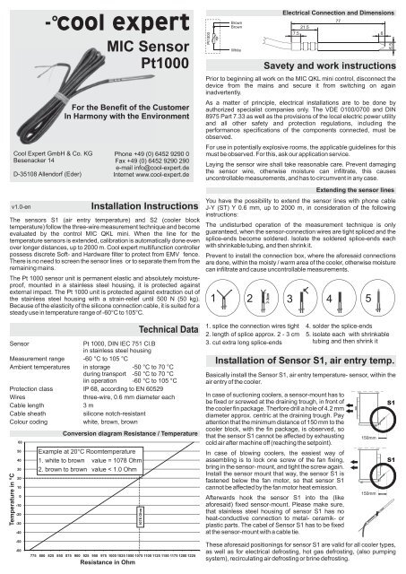
Cool Expert GmbH & Co. KGBesenacker 14D-35108 Allendorf (Eder)For the Benefit of the CustomerIn Harmony with the EnvironmentPhone +49 (0) 6452 9290 0Fax +49 (0) 6452 9290 290e-mail info@cool-expert.deInternet www.cool-expert.deInstallation InstructionsThe sensors S1 (air entry temperature) and S2 (cooler blocktemperature) follow the three-wire measurement technique and becomeevaluated by the control <strong>MIC</strong> QKL mini. When the line for thetemperature sensors is extended, calibration is automatically done evenover longer distances, up to 2000 m. Cool expert multifunction controllerpossess discrete Soft- and Hardware filter to protect from EMV fence.There is no need to screen the sensor lines or to separate them from theremaining mains.The Pt 1000 sensor unit is permanent elastic and absolutely moistureproof,mounted in a stainless steel housing, it is protected againstexternal impact. The Pt 1000 unit is protected against extraction out ofthe stainless steel housing with a strain-relief until 500 N (50 kg).Because of the elasticity of the silicone connection cable, it is suited for asteady use in temperature range of -60°C to 105°C.Technical Data<strong>Sensor</strong>Pt 1000, DIN IEC 751 Cl.Bin stainless steel housingMeasurement range -60 °C to 105 °CAmbient temperatures in storage -50 °C to 70 °Cduring transport -50 °C to 70 °Ciin operation -60 °C to 105 °CProtection class IP 68, according to EN 60529Wiresthree-wire, 0.6 mm diameter eachCable length3 mCable sheathsilicone notch-resistantColour codingwhite, brown, brownTemperature in °Cv1.0-en6050403020100-10-20-30-40Conversion diagram Resistance / TemperatureExample at 20°C Roomtemperature1. white to brown value = 1078 Ohm2. brown to brown value < 1.0 Ohm<strong>MIC</strong> <strong>Sensor</strong><strong>Pt1000</strong>1078 Ohm<strong>Pt1000</strong>BrownBrownWhiteElectrical Connection and Dimensions7721.57.5 6Savety and work instructionsPrior to beginning all work on the <strong>MIC</strong> QKL mini control, disconnect thedevice from the mains and secure it from switching on againinadvertently.As a matter of principle, electrical installations are to be done byauthorized specialist companies only. The VDE 0100/0700 and DIN8975 Part 7.33 as well as the provisions of the local electric power utilityand all other safety and protection regulations, including theperformance specifications of the components connected, must beobserved.For use in potentially explosive rooms, the applicable guidelines for thismust be observed. For this, ask our application service.Laying the sensor wire shall take reasonable care. Prevent damagingthe sensor wire, otherwise moisture can infiltrate, this causesuncontrollable measurements, and has to circumvent in any case.You have the possibility to extend the sensor lines with phone cableJ-Y (ST) Y 0.6 mm, up to 2000 m, in consideration of the followinginstructions:The undisturbed operation of the measurement technique is onlyguaranteed, when the sensor-connection wires are tight spliced and thesplice-ends become soldered. Isolate the soldered splice-ends eachwith shrinkable tubing, and then shrink it.Prevent to install the connection box, where the aforesaid connectionsare done, within the moisty / warm area of the cooler, otherwise moisturecan infiltrate and cause uncontrollable measurements.Installation of <strong>Sensor</strong> S1, air entry temp.Basically install the <strong>Sensor</strong> S1, air entry temperature- sensor, within theair entry of the cooler.In case of suctioning coolers, a sensor-mount has tobe fixed or screwed at the draining trough, in front ofthe cooler fin package. Therfore drill a hole of 4.2 mmdiameter approx. centric at the draining trough. Payattention that the minimum distance of 150 mm to thecooler block, with the fin package, is observed, sothat the sensor S1 cannot be affected by exhaustingcold air after machine off (reaching the setpoint).In case of blowing coolers, the easiest way ofassembling is to lock one screw of the fan fixing,bring in the sensor- mount, and tight the screw again.Install the sensor mount that way, the sensor S1 isfastened below the fan motor, so that sensor S1cannot be affected by the fan motor heat emission.Afterwards hook the sensor S1 into the (likeaforesaid) fixed sensor-mount. Please make sure,that stainless steel housing of sensor S1 has noheat-conductive connection to metal- ceramik- orplastic parts. The cabel of <strong>Sensor</strong> S1 has to be fixedat the sensor-mount with a cable tie.Extending the sensor lines1 2 3 4 51. splice the connection wires tight 4. solder the splice-ends2. length of splice approx. 2 - 3 cm 5. isolate each with shrinkable3. cut extra long splice-ends tubing and then shrink it150mm150mm6.5S1S1-50-60775 800 825 850 875 900 925 950 975 1000 1025 1050 1075 1100 1125 1150 1175 1200 1225Resistance in OhmThese aforesaid positionings for sensor S1 are valid for all cooler types,as well as for electrical defrosting, hot gas defrosting, (also pumpingsystem), recirculating air defrosting or brine defrosting.
Installation of <strong>Sensor</strong> S2, cooler block temp.Here it is necessary (except in case of recirculation air defrosting), to findout which part of the cooler is reaching a defrost end temperature of10°C last. If this part is located, it serves as measurement point for thecooler block temperature sensor S2.Over its total length, the stainless steel housing of <strong>Sensor</strong> S2, must builda constant, safe heat-conducting connection with the cooler block. Tobring in the <strong>Sensor</strong> S2 sideways into the punched voidage of the coolerblock is not permissible, because of the insufficient heat-conductivity. Tobring in the <strong>Sensor</strong> S2 across the cooler core tubing is not advisable.If the cooler manufacturer has defined theplacement for the cooler block temperature<strong>Sensor</strong> by a so called dip tube, the <strong>Sensor</strong> S2becomes inserted 100 mm deep inside of theprovided dip tube, and the sensor cable getsfastened at one bent tube, using a cable tie.In case of brine defrosting, the sensor S2, candirectly get fixed at the tubing, where thedefrosting brine is leaving the cooler again, usinga pipe clip. Pay attention to a good heatconductivity.Secure the sensor S2 from falling out of the cooler block. For this, theconnection cable of S2 has to be fixed safely at the bent tube.In case of electrical defrosting, lay and fix the connection cable inside thecooler with a sufficient safe distance to the tube heating devices.These aforesaid positions for sensor S2 are valid for all cooler types, aswell as for electric defrosting hot gas defrosting (also pumping system),recirculating air defrosting or brine defrosting.Recirculating air defrostingIn case of recirculating air defrosting, basically both sensors have to beconnected. <strong>Sensor</strong> S1 to determine the air entry temperature and<strong>Sensor</strong> S2 to determine the cooler block temperature. The sensor S2has to get fastened inside the lower range of the cooler block, at that sideof refrigerant entry.S2S2S1S1S2S2S1S2S1Electric defrostingThe position for sensor S2 normally is in the upper range of the coolerblock, at that side, where the electric connection for the heatingelements is located. For suctioning coolers within the cooler block at theair entry side, for blowing coolers within the cooler block at the air exitside.S2S2S2S2S2Brine defrostingS2S1S2Here the position for sensor S2 is located in that range of the coolerblock, where the refrigerant leaves the cooler. For suctioning coolerswithin the cooler block at the air entry side, for blowing coolers within thecooler block at the air exit side.S2S2S1RLRLS2S2S2RLVLS1S2VLRLS2S1S2VLS1VLS2S1S2S2RLVLS1S2VLS2S1S2S2RLVLS1S2RLVLHot gas defrostingFor coolers with hot gas defrosting, the measurement point to placesensor S2 is located in that range of the cooler block, where therefrigerant leaves the cooler again. For suctioning coolers, within thecooler block at the air entry side, for blowing coolers within the coolerblock at the air exit side.S2RLVLS1S2RLVL