Spindle Assembly Removal - Little Machine Shop
Spindle Assembly Removal - Little Machine Shop
Spindle Assembly Removal - Little Machine Shop
- No tags were found...

You also want an ePaper? Increase the reach of your titles
YUMPU automatically turns print PDFs into web optimized ePapers that Google loves.
Making the BracketsThere are several brackets and an arm for mounting the display. The first stepis to make these parts.There are two alternates for mounting the X-axis scale. Use Bracket 3 if you donot have a mini mill power feed unit. Use Brackets 7 and 8 if you do have themini mill power feed unit. Parts marked with a single asterisk (*) are usedwithout the power feed unit. Parts marked with a double asterisk (**) are usedwith the power feed unit.You will need the following material for the brackets. We recommend 6061-T6aluminum because it is easy to machine. You can order the material, cut tosize, from Online Metals for about $20.00. Click the link on the left side of the<strong>Little</strong><strong>Machine</strong><strong>Shop</strong>.com home page.Part Size Required Order fromOnline MetalsBracket 1 ½ x 3 x 6½” ½ x 3 x 6½” Aluminum Flat BarBracket 2 ½ x 1½ x 3” ½ x 1½ x 3” Aluminum Flat BarBracket 3*5/8 x ¾ x 4½” ¾ x ¾ x 4½” Aluminum Square BarBracket 4 5/8 x 1½ x 3” ¾ x 1½ x 3” Aluminum Flat BarBracket 5 ½ x 5/8 x 3” 5/8 x 5/8 x 3” Aluminum Square BarDisplay Arm 3/8 x 2 x 4”3/8 x 2 x 4” Aluminum Flat BarBracket 6 ¼ x ¾ x 4” ¼ x ¾ x 4” Aluminum Flat BarBracket 7 1/8 x ¾ x 4” 1/8 x ¾ x 4” Aluminum Flat BarThere are drawings of these parts at the end of this document.2
Bracket 1Bracket 1 mounts on the left side of the saddle. The Y-axis encoder as well asBracket 2 mount on this bracket.Lay out the outside shape of the bracket. Drill two ½” holes about 1/16”outside the layout lines in the corners that are to be radiused.Use a band saw or hacksaw to cut away most of the waste material.Locate and drill the two 0.257” mounting holes. Use ¼” bolts through theseholes to clamp the material on top of a 1-2-3 block so you can mill the part tosize.Move the step clamps as you work around the part. The two bolts will hold thebracket in position.Drill the other holes in this part now, while you have a good reference tomeasure from.Bracket 2Bracket 2 mounts on Bracket 1 and the X-axis encoder mounts on it.3
Bracket 3*Bracket 3 extends the mill table to the left and mounts the end of the X-axisrack. Make this bracket if you do not have a mini mill power feed unit. If youhave the mini mill power feed unit, make brackets 7 and 8 instead.Bracket 4Bracket 4 mounts the Z-axis encoder and the arm for the display.Bracket 5Bracket 5 mounts the display to the display arm.Display ArmThe Display arm goes between Bracket 4 and Bracket 5.Brackets 7 and 8**These brackets extend the mill table to the left and mount the end of theX-axis rack. Make these brackets if you have a mini mill power feed unit. If youdo not have the mini mill power feed unit, make bracket 3 instead.Mounting the DROOnce the brackets are completed, the next step is to mount them on the minimill.Y-axisMount Bracket 2 on Bracket 1 using two 8-32 x ½” socket head cap screws.Mount the Y-axis encoder on Bracket 1 using the screws furnished with theDRO.Using two ¼-20 x ¾” socket head cap screws, mount Bracket 1 on the left sideof the carriage. The top of the bracket should be flush with the top of the4
center of the carriage. Using the bracket as a template, use a transfer punch tomark the hole locations. Using an electric hand drill, drill and tap two ¼-20 NCholes.Once Bracket 1 is mounted, measure the gap between the rack support blocksat the ends of the rack and the base casting.Cut one of the spacer tubes furnished with the DRO across the middle at a 5degree angle. This angle matches the draft angle of the casting. Cut and faceeach spacer to fit between the rack support block and the base casting.Drill and tap 10-32 NF holes in the base casting, using the rack support blocksas templates.Cut one of the short racks to fit. See the DRO User’s Manual for the correctprocedure.X-axisDrill and tap a 10-32 NF hole in the back of the mill table near the right end.The hole should be 3/8” up from the bottom of the table, and 3/8” in from theend of the table.Mount the X-axis encoder on Bracket 2.5
If you do not have a mini mill power feed unit, mount Bracket 3 on the end ofthe table, using an M6x16 socket head cap screw. Use the existing hole in theend of the table.Measure the gap between the rack support blocks at the ends of the rack andthe table and Bracket 3. Cut and face spacers, or use a few washers to fill thegap.If you have a mini mill power feed unit, assemble brackets 7 and 8 using two#6-21 x 3/8” socket head cap screws. The relieved area on bracket 7 facesaway from bracket 8.Sandwich bracket 8 between the mini mill power feed motor unit and the milltable. Use the existing socket head cap screws from the power feed unit tomount both the power feed and bracket 8.Cut the long rack to fit this axis. See the DRO User’s Manual for the correctprocedure.6
Z-axisRemove the Z-axis scale from the left side of the column.Using the spacer tubes supplied with the DRO, cut and face two spacers 3/16”long.Drill and tap a 10-32 NF hole for the upper rack support block centeredhorizontally on the angled face from which you removed the scale. Position theblock as high as you can on this face.Drill and tap a 10-32 NF hole for the lower rack support block centeredhorizontally on the angled face from which you removed the scale. Position theblock as low as you can on this face.Cut one of the short racks to fit between the two rack support blocks. See theDRO User’s Manual for the correct procedure.Mount the Z-axis encoder on Bracket 4. Then mount the two rack supportblocks on the column.Use a transfer punch to mark the mounting holes for Bracket 4. Drill and taptwo 10-32 NF holes to mount Bracket 4. Mount Bracket 4 with two 10-32 x ½”flat head socket screws.7
DisplayMount Bracket 5 on the back of the display with two 10-32 x ½” flat headsocket screws.Mount the Display Arm on Bracket 5 using two 8-32 NC x 1/4 ” self-locking dogpoint setscrews.Mount the Display Arm on Bracket 4 using two 8-32 NC x 1/4 ” self-locking dogpoint setscrews.8
WiringPlug the wire from the X-axis encoder into the left connector on the bottom ofthe display.Plug the wire from the y-axis encoder into the center connector on the bottomof the display.Plug the wire from the Z-axis encoder into the right connector on the bottomof the display.Plug the wire from the power supply into the connector on the bottom of thedisplay.Use split wire loom to dress and protect the wiring. Place a plastic cable tie ateach end to prevent the wires from coming out.9
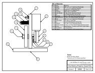
6.1250.5004.1250.1253.8253.637Ø0.1702.7500.165Ø0.2570.500Ø0.2850.5620.1560.8122.6251.8752.1252.3981.1251.4372.188R0.250Ø0.50.1252.5253.769Ø0.1560.2505.881<strong>Little</strong><strong>Machine</strong><strong>Shop</strong>.com© 2001 <strong>Little</strong><strong>Machine</strong><strong>Shop</strong>.com. All rights reserved.DRO Bracket 1Revision 0Scale 1:1Sheet 1 of 1
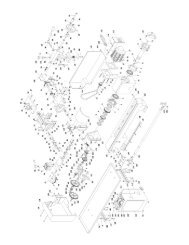
2.6252.250.1880.187Ø0.1562.3580.500.2440.37510.1521.3130.6570.501.500.750.3750.1870.3758-32 NC<strong>Little</strong><strong>Machine</strong><strong>Shop</strong>.com© 2001 <strong>Little</strong><strong>Machine</strong><strong>Shop</strong>.com. All rights reserved.DRO Bracket 2Revision 0Scale 1:1Sheet 1 of 1
4.1250.2500.090.6250.500Ø0.2363.7500.7500.500 0.5630.350 0.3750.384Ø0.1591.000<strong>Little</strong><strong>Machine</strong><strong>Shop</strong>.com© 2001 <strong>Little</strong><strong>Machine</strong><strong>Shop</strong>.com. All rights reserved.DRO Bracket 3Revision 0Scale 1:1Sheet 1 of 1
2.6002.358Ø0.1560.2440.2775°0.279Ø0.2811.50.5000.2700.55Ø0.196 Ø0.4110.8750.2500.6252.052.33#8 - 32 NC0.375R0.09<strong>Little</strong><strong>Machine</strong><strong>Shop</strong>.com© 2001 <strong>Little</strong><strong>Machine</strong><strong>Shop</strong>.com. All rights reserved.DRO Bracket 4Revision 0Scale 1:1Sheet 1 of 1
2.600 0.6250.2500.5000.2700.5500.125Ø0.196 Ø0.411 #8 - 32 NC2.0500.3752.330<strong>Little</strong><strong>Machine</strong><strong>Shop</strong>.com© 2001 <strong>Little</strong><strong>Machine</strong><strong>Shop</strong>.com. All rights reserved.DRO Bracket 5Revision 0Scale 1:1Sheet 1 of 1
4.0000.3750.125Ø0.100 R0.0303.8750.1252.000<strong>Little</strong><strong>Machine</strong><strong>Shop</strong>.com© 2001 <strong>Little</strong><strong>Machine</strong><strong>Shop</strong>.com. All rights reserved.DRO Readout ArmRevision 0Scale 1:1Sheet 1 of 1
40.2503.6273.1250.1490.3120.1250.75R0.250.6250.375#10 - 32 ThreadØ0.159 Tap drill0.125#6-32 ThreadØ0.106 Tap drill<strong>Little</strong><strong>Machine</strong><strong>Shop</strong>.comDRO Bracket 7© 2001 <strong>Little</strong><strong>Machine</strong><strong>Shop</strong>.com. All rights reserved.Revision 0Scale 1:1Sheet 1 of 1
3.6773.5430.7090.5750.1250.625 0.400 0.1250.1870.1250.750Ø0.1383.938Ø0.248<strong>Little</strong><strong>Machine</strong><strong>Shop</strong>.comDRO Bracket 8© 2003 <strong>Little</strong><strong>Machine</strong><strong>Shop</strong>.com. All rights reserved.Revision 0Scale 1:1Sheet 1 of 1