Getting the Utmost From the AR-88.pdf
Getting the Utmost From the AR-88.pdf
Getting the Utmost From the AR-88.pdf
- No tags were found...
Create successful ePaper yourself
Turn your PDF publications into a flip-book with our unique Google optimized e-Paper software.
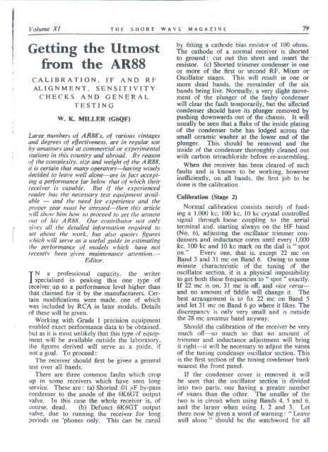
Volume XI THE SHORT WAVE MAGAZINE 79<strong>Getting</strong> <strong>the</strong> <strong>Utmost</strong>from <strong>the</strong> <strong>AR</strong>88CALIBRATIO N. IF AND RFAL I G N MEN T. S ENS I T I V I T YCHECKS AND GENERALTESTINGW. K. MILLER (G6QF)Lafl.!e numbers of <strong>AR</strong>88's, of various "imagescJlld degrees of effectiveness, are ill regular llseby amateur.r alld at commercial or experimental'tations in this cOllntry and abroad. By reasonuf <strong>the</strong> complexity, size and weight of <strong>the</strong> A R88,it is certain that many operalOrs-hal'ing wiselydecided 10 Leave well alone-are in fact accept·i/lg a performance far belol
80 THE SIiORT WAYE "'IAGAZINE A "ril, 1953
Volume Xl THE SHORT WAVE MAGAZINE 81General appearance of <strong>the</strong> famous <strong>AR</strong>88, in use a.t a g,reat many stations at hOnle and overseas. The tunin~ dial is ..:entre top. with.... . <strong>the</strong> band indication panel on <strong>the</strong> left and <strong>the</strong> S·meter to <strong>the</strong> right.IF Set-up. The IF crystal frequency is 455KC. The IF signal from <strong>the</strong> wobbulator set:at 455 kc is fed through a .0 I .',F condenser topin 5 of <strong>the</strong> 6SA7 mixer valve. The 615()scillator valve is not removed during IF:alignment. Oscilloscope input is taken from.chassis and point C on IF transformer 1'9.Time base voltage is fed from oscilloscope towobbulator.Control SettingsOil-off lwilc.:hRcc. Mod.Band S"'itch, Band J LF end.RF gainMax.A IIdio gain \1 ax .SelediFify Position 1.AVC Position 4.Crysllll P,', ;;I.\'illg COlllro! C75 Half-mesh.
82 THE SHORT WAVE MAGAZINE April. 1951and. working with <strong>the</strong> receiver turned on itsleft side, to tune <strong>the</strong> top and bottom trimmersat <strong>the</strong> same time. With care and attention to<strong>the</strong> curve centreing and amplitude, it is quitea straightforward job, but one which does takesome time. Unless <strong>the</strong> receiver has been badlymis-used, no trouble should arise from <strong>the</strong> IFcomponents, as <strong>the</strong> writer has yet to find <strong>the</strong>first fault in this respect. Do not be misled;nto thinking <strong>the</strong> IF transformer is a "dud."It is almost always your tuning which is atfault!Testing IF Sensitivity. Remove oscilloscopeand wobbulator leads from receiver. Connectmatched output meter to output terminals atback of receiver. Set signal generator at 455kc and feed through .01 flF condenser to pin 5of mixer as before, and-with selectivity switchin pos. 3-rock <strong>the</strong> signal generator tuning togive maximum output on meter, <strong>the</strong>n switchselectivity switch to pos. 2 for future readings.Set modulation on signal generator at 30% andfeed in sufficient signal to bring output meterreading up to one watt. Read off <strong>the</strong> inputon <strong>the</strong> scale of signal generator. This maybe anything from 600 to 1000 microvolts on<strong>the</strong> first test. A note should be made of thisfigure.Now take out <strong>the</strong> first and second RF valves(6SGTs) and removing each of <strong>the</strong> 6SG7 IFvalves in turn, substitute one or o<strong>the</strong>r in turnof <strong>the</strong> RF valves. This should show on <strong>the</strong>outout meter if <strong>the</strong> valves are all of a standardefficiency. It a substitution results in an increasein output, leaving <strong>the</strong> valve which caused<strong>the</strong> impravement in circuit. Should sparevalves be available <strong>the</strong>y should be tested inturn, to obtain <strong>the</strong> best team in <strong>the</strong> IF stages.It better valves have been found for <strong>the</strong> IF's<strong>the</strong> input required from <strong>the</strong> signal generatorwill, of course, be smaller. to give one wattoutout. The IF's should now be trimmed upwith <strong>the</strong> substituted valves in use. using <strong>the</strong>oscilloscope as before, and <strong>the</strong> input requiredfor one watt output again measured. Thisshould be lower than <strong>the</strong> previous figure. butmay still be around 600 to 700 microvolts. Toimprove this figure still fur<strong>the</strong>r remove <strong>the</strong>6SA 7 melal mixer valve and substitute a 6SA 7glass type. If one or two of <strong>the</strong> glass ones areavailable. try <strong>the</strong>m in turn. not forgetting tore-align with each change.The result in almost every case is that <strong>the</strong>required IF input for one watt of output willdrop frolll aboul 600 microvolls 10 belween 80and lOO-which is a considerable gain .The IF efficiency measurement is alwaysmade with selectivity switch in pos. 2. butconstant checks of signal frequency are required,to be made by switching to pos. 3and rocking generator frequency.Once this figure is obtained with <strong>the</strong> curvescentral on all positions of selectivity switch.<strong>the</strong> IF's can be sealed by painting <strong>the</strong> trimmerspindles with a spot of shellac to preventaccidental rotation.If any difficulty is found in adjusting a particularIF transformer, <strong>the</strong> signal generatorshould be fed through <strong>the</strong> grid of <strong>the</strong> preceding.IF valve and <strong>the</strong> stage roughly aligned: <strong>the</strong>signal generator is <strong>the</strong>n returned to pin 5 of <strong>the</strong>6SA 7 for final alignment.Crystal Phasing adjustmelll. Connect a highresistance sensitive DC voltmeter to point Con last IF transformer. Feed signal generatortuned to 7 kc off IF resonance to pin 5 of6SA 7 mixer, and adjust C75 for minimumresponse.Adjustment Crystal Load Circuit(I) With set-up as for IF alignment andselectivity switch on pos. 3, rock signal generatorthrough IF frequency and adjust L34 forsymmetrical round-topped curve. (2) Withselectivity switch in pos. 4 adjust C81 forsymmetrical curve. (3) With selectivity switchin pos. 5 adjust C80 for symmetrical curve.rocking signal generator as for I and 2.Wave Trap Adjustmetll. With range switchon Band I, feed a modulated signal of 455 kcinto aerial and ground and adjust L57 on backof chassis for minimum output on meter orspeaker.This adjustment should be made before finalRF alignment.I 2 3 45 ' 54 3 2 "'
J·olulIle XI THE SHORT WAVE MAGAZINE 83The.<strong>AR</strong>88 with tbe lid open, showing chassis layour and pla cement of main parts. The accompanying article s uggests how <strong>the</strong>recenercan be checked and adjusted for nlaximunl pcrfonnance on <strong>the</strong> amateur bands. This should not he undertaken withoutp roper test equipment and experience in its use.RF Alignment (Stage .t)Connect matched output meter to outputtermmals of receiver, <strong>the</strong>n connect signalgenerator with 30% modulation \·ia a 200-ohmresistor to aerial and ground. (Shorting linkfrom o<strong>the</strong>r aerial terminal to ground is kft illposition.) The manufacturers ~recornmend that<strong>the</strong> meter be connected across <strong>the</strong> voice coilof <strong>the</strong> speaker. but <strong>the</strong> figures quoted later inthiS article refer to readings on J. i\1arconimatched output meter without speaker Ic'ad .Control ~t.,~ett i" gsTOlle COll1ra/AIIICfIf//l TrimlllerOn-nf] .\'11,//('11Range S'II"itchRF Caill:1udio Caincl VC5iefe("lil'i/\' SI\'ifchFu ll y clockwisL'Adjustt:d for rH:!X . outputat Hr t'nJ 01 ,,',1.: 11h; .lIld ill tum.Rl"c. ~'Lh" !.To hand hr.: ln ~ ~t! i~nl"dMax.M::tx.Pusitilln ..J..Pu"iti(l[iBegin alignment on Band 6 by feeding 30.5me from signal generator. T une receiver formaximum output and adjust aerial tuning onfront panel for maximum output. Adjust 1stand 2nd RF trimmers C45 and eG8 carefullyfor maximunl output. Then se t signal generatorto 22.5 me and retune receiver for maximumoutput, but do not alter <strong>the</strong> previous settlllgof aerial tuning on front panel. (This is tunedfor maximum at <strong>the</strong> HF end only of each bandin turn, and is left so tuned wh~n <strong>the</strong> remainingadjustments arc made at <strong>the</strong> LF end of eachband.) Adjust aerial inductance trimmer Ll2(on back of chassis) and 1st and 2nd RFtrimmers L21 and L31 fo r maximum output.Repeat <strong>the</strong>se adjustments at <strong>the</strong> HF and LFends several times to obtain peak output.The writer obtained 5 watts output for onemicrovolt input consistently at both ends of thishand on a properly aligned receiver.Switch off modulator fr011l signal generatorand read off <strong>the</strong> noise-Ie\el on meter. The
84 THE SHORT WAVE MAGAZINE April. 1953reading should be below one watt. but if itis higher remove <strong>the</strong> 1st RF valve and substitutea 6AC7. or 717A. or 6SH7 for <strong>the</strong> 6SG7and re-align_ This should reduce <strong>the</strong> noise considerablywithout alIecting <strong>the</strong> output withmodulation on generator signal.Band 5. Tune 22.4 mc generator signal onreceiver. adjust aerial tuning and C43 and C66.all for maximum output. Tune 16.4 mcgenerator signal on receiver and adjust LlO(on back of chassis) and L20 and L30. all formaximum output. Repeat several times. Outputshould be between 4 and 5 watts for onemicrovolt input.Band 4. Tune 16.4 mc generator signal onreceiver and adjust aerial tuning and C41 andC64. all for maximum output. Tune 12.2 megenerator signal on receiver and adjust L8(on back of chassis) and Ll9 and 29 for fulloutput. Repeat several times. Output shouldbe 3.5 to 4.5 watts for one microvolt input.Band 3_ Tune 11.5 me generator signal onreceiver. adjust aerial tuning and C39 and C62.all for full output. Tune 4.6 me generator.signal on receiver and adjust L6 (on back ofchassis) and Ll8 and L28 for maximum output.Repeat several times. Output should be3_0 to 3.5 watts for 1 microvolt input.Band 2. Tune 4.4 . mc generator ' signal onreceiver. adjust aerial tuning and C38 and C60,all for maximum output Tune 1.7 me generatorsignal on receiver. adjust L4 (on back ofchassis) and Ll6 and L26, all for full output.Repeat several times. Output should be 2.510 3.5 watts for one microvolt input.Band 1. Tune 1500 kc generator signal onreceiver. adjust aerial tuning and C37 and C59.all for full output. Tune 550 kc generatorsignal on receiver and ad just L2 (on back ofchassis) and L14 and L24 for maximum output.Repeat several times. Output should be I to1.5 watts for input of one microvolt.When <strong>the</strong> receiver ' has been tuned up topeak performance with <strong>the</strong> modifications mentioned.it may be found that IF oscillationappears. as indicated by unwanted whistles atodd places on one band, or perhaps several.To eliminate this with certainty, <strong>the</strong> writerspent many hours before finding that <strong>the</strong>trouble was caused by <strong>the</strong> close proximity toeach o<strong>the</strong>r of <strong>the</strong> anode, screen and cathodeleads of <strong>the</strong> last 6SG7 IF valve. These leadseach go to .05 ... F fixed condensers on <strong>the</strong>chassis front. and should be cut out andrenlaced by screened leads. as short as possible.with <strong>the</strong> screening braid well grounded.Since <strong>the</strong> discovery of this cure, <strong>the</strong> manufacturershave included secened leads at thispoint . as a standard modification. This will<strong>the</strong>refore only apply to earlier models. Yourscan be identified by <strong>the</strong> main tuning dial.which is of translucent material with figuresin black. Later models (which include <strong>the</strong>modification mentioned) are provided with dialsof <strong>the</strong> same material. but with alternate bandsmarked all black with translucent figures.Readers wishing to fit an S-meter (5 mAf.s.d. right hand zero) will find <strong>the</strong> adjustingpotentiometer in <strong>the</strong> centre back of chassis.provided with screwdriver slot.The "0" in <strong>the</strong> <strong>AR</strong>880 indicates that provisionis made in <strong>the</strong> receiver design fordiversity reception. R.C.A. manufacture astandard rack to accommodate two <strong>AR</strong>88D's.and a diversity switching unit which automaticallyselects <strong>the</strong> most useful signal fromseparate aerials, and feeds this signal to one oro<strong>the</strong>r of <strong>the</strong> receivers. The output is <strong>the</strong>reforekept as near as possible at a constant level,irrespective of fading in one or o<strong>the</strong>r of <strong>the</strong>signal paths.So, if you want to keep track of that fadingOX, this is <strong>the</strong> set-up you require. and <strong>the</strong>writer does not know of a better. Beforeorderin,g. however, make sure you have animport licence, a dollar bank balance. and anaerial farm !It is realised. of course. that much informationcan be obtained from <strong>the</strong> manufacturers'handbook, but <strong>the</strong> writer has tried to set outhis own results and conclusions, arrived at aftermonths of concentrated study and experiment.toge<strong>the</strong>r with modifications which <strong>the</strong> readermay care to try out.MORE ABOUT THE TIFD AERIALT}le article by G2NS in our issue for January, 1953.describing an unusually effective multi-band aerial forconfined spaces developed by W3HH. has aroused agood deal of interest. Many versions of <strong>the</strong> design arenow being operated by G stations, and following aresome fur<strong>the</strong>r notes on <strong>the</strong> TIFD offered by G2NSafter correspondence with <strong>the</strong> States: The best angle oftilt is 30° and <strong>the</strong> optimum value of <strong>the</strong> terminatingresistance is fairly critical for best results, being 390ohms for a 300-0hm feed line. and 650 ohms for a 600-ohm line. These resistors should be non-inductiveand capable of dissipating <strong>the</strong> power involved. Wirewoundresistors will do, but if <strong>the</strong>y are used <strong>the</strong> systemas a whole tends to become non-aperiodic and calJsfor changes in <strong>the</strong> method of coupling when goingfrom band to band. High-wattage wire-wound resistorsare still readily available, but carbon types are preferableif <strong>the</strong>y can be obtained. It has been found in practicethat a three-band version of <strong>the</strong> T2FD can be loadedup and operated efficiently on five bands.


