Instruction manual "optoNCDT 2300" - Micro-Epsilon
Instruction manual "optoNCDT 2300" - Micro-Epsilon
Instruction manual "optoNCDT 2300" - Micro-Epsilon

Create successful ePaper yourself
Turn your PDF publications into a flip-book with our unique Google optimized e-Paper software.
<strong>Instruction</strong> Manual<strong>optoNCDT</strong> 2300ILD 2300-2ILD 2300-50ILD2300-2LLILD2300-2BLILD 2310-10ILD 2300-5ILD 2300-100ILD2300-10LLILD2300-5BLILD 2310-20ILD 2300-10ILD 2300-200ILD2300-20LLILD2310-50BLILD 2310-50ILD 2300-20ILD2300-50LLILD 2300-40
MICRO-EPSILONMESSTECHNIKGmbH & Co. KGKönigbacher Strasse 1594496 Ortenburg / GermanyTel. +49 (0) 8542 / 168-0Fax +49 (0) 8542 / 168-90e-mail info@micro-epsilon.dewww.micro-epsilon.comCertified acc. to DIN EN ISO 9001: 2008EtherCAT® is registered trademark and patented technology,licensed by Beckhoff Automation GmbH, Germany.
Contents1. Safety....................................................................................................................................... 111.1 Symbols Used................................................................................................................................................ 111.2 Warnings......................................................................................................................................................... 111.3 CE Compliance............................................................................................................................................... 121.4 Proper Use...................................................................................................................................................... 131.5 Proper Environment........................................................................................................................................ 132. Laser Class.............................................................................................................................. 143. Functional Principle, Technical Data...................................................................................... 173.1 Short Description............................................................................................................................................ 173.2 Real Time Control (A-RTSC)........................................................................................................................... 173.3 Exposure Control............................................................................................................................................ 173.4 Technical Data................................................................................................................................................ 183.5 Indicator Elements at Sensor......................................................................................................................... 234. Delivery.................................................................................................................................... 244.1 Unpacking....................................................................................................................................................... 244.2 Storage........................................................................................................................................................... 245. Installation............................................................................................................................... 255.1 Diffuse Reflection............................................................................................................................................ 255.2 Direct Reflection.............................................................................................................................................. 295.3 Electrical Connections.................................................................................................................................... 315.3.1 Connection Possibilities................................................................................................................ 315.3.2 Supply Voltage.............................................................................................................................. 335.3.3 Laser on......................................................................................................................................... 335.3.4 Input and Outputs......................................................................................................................... 345.3.5 Ethernet......................................................................................................................................... 355.3.6 EtherCAT....................................................................................................................................... 365.3.7 Connector and Sensor Cable....................................................................................................... 37<strong>optoNCDT</strong> 2300
7.6.2 Trigger Counter............................................................................................................................. 687.6.2.1 General......................................................................................................................... 687.6.2.2 Trigger ID (T)................................................................................................................ 687.6.2.3 Trigger Event Counter.................................................................................................. 687.6.2.4 Trigger Measurement Value Counter........................................................................... 697.6.2.5 Example........................................................................................................................ 697.6.2.6 Function........................................................................................................................ 707.6.2.7 Presets for Trigger Mode and Trigger Edge................................................................ 717.6.3 Synchronization............................................................................................................................. 727.7 Loading, Saving, Extras ................................................................................................................................. 747.7.1 Loading/Saving Settings............................................................................................................... 747.7.2 Extras............................................................................................................................................. 758. Digital Interfaces..................................................................................................................... 768.1 Preliminary Remarks....................................................................................................................................... 768.2 Ethernet........................................................................................................................................................... 768.2.1 Default Settings............................................................................................................................. 768.2.2 Data Format Output Values, Measurement Value Frame Ethernet............................................... 778.2.3 Measurement Data Transmission to a Measurement Value Server, Measurement Value Block.. 818.2.4 Ethernet Video Signal Transmission............................................................................................. 838.3 RS422............................................................................................................................................................. 838.4 EtherCAT......................................................................................................................................................... 858.5 Change Ethernet to EtherCAT........................................................................................................................ 859. Value Output............................................................................................................................ 869.1 RS422............................................................................................................................................................. 869.1.1 Possible Output Values and Output Sequence............................................................................ 889.1.2 Error Codes................................................................................................................................... 899.2 Ethernet........................................................................................................................................................... 909.3 EtherCAT......................................................................................................................................................... 909.4 Analog Output................................................................................................................................................. 919.5 Error Handling................................................................................................................................................ 91<strong>optoNCDT</strong> 2300
10. <strong>Instruction</strong>s for Operating...................................................................................................... 9210.1 Reflection Factor of the Target Surface.......................................................................................................... 9210.2 Error Influences ............................................................................................................................................. 9310.2.1 Light from other Sources .............................................................................................................. 9310.2.2 Color Differences .......................................................................................................................... 9310.2.3 Surface Roughness ...................................................................................................................... 9310.2.4 Temperature Influences ................................................................................................................ 9310.2.5 Mechanical Vibration .................................................................................................................... 9310.2.6 Movement Blurs ............................................................................................................................ 9310.2.7 Angle Influences ........................................................................................................................... 9410.3 Optimizing the Measuring Accuracy ............................................................................................................. 9510.4 Cleaning.......................................................................................................................................................... 9610.5 Protective Housing ........................................................................................................................................ 9710.5.1 Versions......................................................................................................................................... 9710.5.2 Guidelines ..................................................................................................................................... 9710.5.3 Delivery ......................................................................................................................................... 9711. RS422 Connection with USB Converter............................................................................... 10012. Software Support with MEDAQLib....................................................................................... 10013. Warranty................................................................................................................................. 10114. Decommissioning, Disposal................................................................................................. 10115. Service, Repair...................................................................................................................... 102AppendixA 1 Optional Accessories.................................................................................................................................... 103A 2 Factory Setting.............................................................................................................................................. 106A 2.1 Parameters.................................................................................................................................................... 106A 2.2 Set Default Settings...................................................................................................................................... 107A 3 PC2300-0.5/Y................................................................................................................................................ 108A 4 PC2300-x/OE................................................................................................................................................ 109A 5 IF2004/USB................................................................................................................................................... 110<strong>optoNCDT</strong> 2300
<strong>optoNCDT</strong> 2300A 6 ASCII Communication with Sensor.............................................................................................................. 111A 6.1 General......................................................................................................................................................... 111A 6.2 Commands Overview................................................................................................................................... 113A 6.3 General Commands..................................................................................................................................... 117A 6.3.1 General ....................................................................................................................................... 117A 6.3.1.1 Help............................................................................................................................ 117A 6.3.1.2 Sensor Information .................................................................................................... 117A 6.3.1.3 Synchronization ........................................................................................................ 118A 6.3.1.4 Booting the Sensor ................................................................................................... 118A 6.3.1.5 Reset Counter............................................................................................................ 119A 6.3.1.6 Switching the Command Reply, ASCII Interface ...................................................... 119A 6.3.1.7 PRINT......................................................................................................................... 120A 6.3.2 User Level.................................................................................................................................... 121A 6.3.2.1 Change of the User Level........................................................................................... 121A 6.3.2.2 Change to User in the User Level.............................................................................. 121A 6.3.2.3 User Level Request.................................................................................................... 121A 6.3.2.4 Set Standard User...................................................................................................... 121A 6.3.2.5 Change Password...................................................................................................... 121A 6.3.3 Triggering..................................................................................................................................... 122A 6.3.3.1 Trigger Selection ....................................................................................................... 122A 6.3.3.2 Effect of the Trigger Input........................................................................................... 122A 6.3.3.3 Trigger Level .............................................................................................................. 122A 6.3.3.4 Number of Measurement Values Displayed.............................................................. 123A 6.3.3.5 Software Trigger Pulse............................................................................................... 123A 6.3.3.6 Trigger Output all Values............................................................................................ 123A 6.3.4 Interfaces..................................................................................................................................... 124A 6.3.4.1 Ethernet...................................................................................................................... 124A 6.3.4.2 Setting Measurement Server..................................................................................... 124A 6.3.4.3 Setting RS422 ........................................................................................................... 124A 6.3.4.4 Change between Ethernet / EtherCAT....................................................................... 125A 6.3.4.5 Units Web-Interface.................................................................................................... 125A 6.3.5 Load / Save Settings................................................................................................................... 125A 6.3.5.1 Save Parameter ......................................................................................................... 125A 6.3.5.2 Load Parameter ......................................................................................................... 125A 6.3.5.3 Default Settings ......................................................................................................... 125
<strong>optoNCDT</strong> 2300A 6.4 Measurement................................................................................................................................................ 126A 6.4.1 General........................................................................................................................................ 126A 6.4.1.1 Measurement Mode .................................................................................................. 126A 6.4.1.2 Selection of Peak for Displacement Measurement.................................................... 126A 6.4.1.3 Video Signal Request................................................................................................. 126A 6.4.1.4 Measuring Rate.......................................................................................................... 126A 6.4.1.5 Laser Power................................................................................................................ 127A 6.4.2 Video Signal................................................................................................................................ 127A 6.4.2.1 Reduction of Region of Interest (ROI)........................................................................ 127A 6.4.2.2 Video Averaging......................................................................................................... 127A 6.4.3 Material Data Base...................................................................................................................... 128A 6.4.3.1 Reading of Material Data Base.................................................................................. 128A 6.4.3.2 Choose Material......................................................................................................... 128A 6.4.3.3 Display Material ......................................................................................................... 128A 6.4.3.4 Edit Material Table...................................................................................................... 129A 6.4.3.5 Delete Material Table.................................................................................................. 129A 6.4.4 Measurement Value Processing................................................................................................. 129A 6.4.4.1 Averaging of Measurement Value.............................................................................. 129A 6.4.4.2 Spike Correction........................................................................................................ 129A 6.4.4.3 Values used for Statistics........................................................................................... 130A 6.4.4.4 Reset the Statistics..................................................................................................... 130A 6.4.4.5 Setting Masters / Zero................................................................................................ 130A 6.5 Data Output.................................................................................................................................................. 131A 6.5.1 General........................................................................................................................................ 131A 6.5.1.1 Selection Digital Output............................................................................................. 131A 6.5.1.2 Output Data Rate........................................................................................................ 131A 6.5.1.3 Error Processing........................................................................................................ 131A 6.5.1.4 Specified Measured Value Output............................................................................. 131A 6.5.2 Select Measurement Values to be Output.................................................................................. 132A 6.5.2.1 Request Data Selection.............................................................................................. 132A 6.5.2.2 Data Selection Displacement Measurement ............................................................ 132A 6.5.2.3 Data Selection Thickness Measurement................................................................... 132A 6.5.2.4 Data Selection Statistic Values................................................................................... 133A 6.5.2.5 Data Selection Optional Values ................................................................................ 133A 6.5.2.6 Set Video Output........................................................................................................ 133A 6.6 Example Command Sequence During Measurement Selection................................................................. 134A 6.7 Error Messages............................................................................................................................................. 135
A 7 EtherCAT....................................................................................................................................................... 139A 7.1 Generall......................................................................................................................................................... 139A 7.2 Preamble....................................................................................................................................................... 139A 7.2.1 Structure of EtherCAT®-Frames................................................................................................. 139A 7.2.2 EtherCAT® Services.................................................................................................................... 140A 7.2.3 Addressing and FMMUs.............................................................................................................. 141A 7.2.4 Sync Manager............................................................................................................................. 141A 7.2.5 EtherCAT State Machine............................................................................................................. 142A 7.2.6 CANopen over EtherCAT............................................................................................................ 142A 7.2.7 Process Data PDO Mapping....................................................................................................... 143A 7.2.8 Service Data SDO Service........................................................................................................... 144A 7.3 CoE – Object Directory................................................................................................................................. 145A 7.3.1 Characteristics............................................................................................................................. 145A 7.3.2 Communication Specific Standard Objects (CiA DS-301)......................................................... 145A 7.3.2.1 Object 1000h: Device type......................................................................................... 146A 7.3.2.2 Object 1001h: Error register...................................................................................... 146A 7.3.2.3 Object 1003h: Predefined error field.......................................................................... 146A 7.3.2.4 Object 1008h: Manufacturer device name................................................................ 146A 7.3.2.5 Object 1009h: Hardware version............................................................................... 146A 7.3.2.6 Object 100Ah: Software version................................................................................ 147A 7.3.2.7 Object 1018h: Device identification........................................................................... 147A 7.3.2.8 Object 1A00h: TxPDO Mapping................................................................................. 147A 7.3.2.9 Object 1A01 up to 1A63: TxPDO mapping................................................................ 148A 7.3.2.10 Object 1C00h: Synchronous manager type.............................................................. 148A 7.3.2.11 Object 1C13h: TxPDO assign.................................................................................... 148A 7.3.2.12 Object 1C33h: Synchronous parameter.................................................................... 149A 7.3.3 Manufacturer Specific Objects.................................................................................................... 150A 7.3.3.1 Object 2001h: User level............................................................................................ 151A 7.3.3.2 Object 2005h: Sensor informations (further)............................................................. 151A 7.3.3.3 Object 2010h: Loading/saving settings..................................................................... 152A 7.3.3.4 Object 2050h: Advanced settings.............................................................................. 152A 7.3.3.5 Object 2101h: Reset................................................................................................... 152A 7.3.3.6 Object 2105h: Factory settings.................................................................................. 153A 7.3.3.7 Object 2131h: Light source........................................................................................ 153A 7.3.3.8 Object 2154h: Measuring program............................................................................ 153A 7.3.3.9 Object 2161h: Peak selection at distance measuring............................................... 153A 7.3.3.10 Object 2181h: Averaging, error processing, statistics and spike correction............ 154A 7.3.3.11 Object 21B0h: Digital interfaces, selection of transmitted data (measurements)..... 156A 7.3.3.12 Object 21C0h: Ethernet............................................................................................. 157<strong>optoNCDT</strong> 2300
<strong>optoNCDT</strong> 2300A 7.3.3.13 Object 21E0h: Zeroing/Mastering.............................................................................. 158A 7.3.3.14 Object 2250h: Measuring rate................................................................................... 158A 7.3.3.15 Object 2410h: Triggermodi........................................................................................ 159A 7.3.3.16 Object 2711h: Reduction of region of interest........................................................... 160A 7.3.3.17 Object 2800h: Material info........................................................................................ 160A 7.3.3.18 Object 2801h: Material select.................................................................................... 161A 7.3.3.19 Object 2802h: Material table edit............................................................................... 161A 7.3.3.20 Object 603Fh: Sensor - error..................................................................................... 162A 7.3.3.21 Object 6065h: Measurement values.......................................................................... 162A 7.4 Error Codes for SDO Services...................................................................................................................... 162A 7.5 Measurement Data Formats......................................................................................................................... 164A 7.6 ILD2300 with Oversampling in EtherCAT..................................................................................................... 164A 7.7 ILD2300 Distributed Clock............................................................................................................................ 172A 7.7.1 Synchronization........................................................................................................................... 172A 7.7.1.1 Synchronization off.................................................................................................... 173A 7.7.1.2 Slave........................................................................................................................... 173A 7.7.1.3 Slave Alternating........................................................................................................ 173A 7.7.1.4 Apply Selected Settings ............................................................................................ 173A 7.7.1.5 Setting Regardless of TwinCat................................................................................... 173A 7.8 Measuring Rates and Measurement Values with EtherCAT........................................................................ 174A 7.9 Meaning of EtherCAT-STATUS-LED............................................................................................................. 174A 7.10 EtherCAT Configuration with the Beckhoff TwinCAT©-Manager................................................................. 175A 7.11 Finish EtherCAT............................................................................................................................................ 181A 7.12 Troubleshooting............................................................................................................................................ 182A 8 Control Menu................................................................................................................................................ 186
Safety1. SafetyThe handling of the sensor assumes knowledge of the instruction <strong>manual</strong>.1.1 Symbols UsedThe following symbols are used in this instruction <strong>manual</strong>:iMeasure1.2 WarningsIndicates a hazardous situation which, if not avoided, may result in minor or moderateinjury.Indicates a situation which, if not avoided, may lead to property damage.Indicates a user action.Indicates a user tip.Indicates hardware or a button/menu in the software.Avoid unnecessary laser radiation to be exposed to the human body.Switch off the sensor for cleaning and maintenance.Switch off the sensor for system maintenance and repair if the sensor is integrated into a system.Caution - use of controls or adjustments or performance of procedures other than those specified may causeharm.Connect the power supply and the display-/output device in accordance with the safety regulations for electricalequipment.> > Danger of injury> > Damage to or destruction of the sensorAvoid shock and vibration to the sensor.> > Damage to or destruction of the sensorThe power supply may not exceed the specified limits.<strong>optoNCDT</strong> 2300Page 11
Safety> > Damage to or destruction of the sensorProtect the sensor cable against damage.> > Destruction of the sensor> > Failure of the measuring deviceAvoid continuous exposure to fluids on the sensor.> > Damage to or destruction of the sensorAvoid exposure to aggressive materials (washing agent, penetrating liquids or similar) on the sensor.> > Damage to or destruction of the sensor1.3 CE ComplianceThe following applies to the <strong>optoNCDT</strong> 2300: EMC regulation 2004/108/ECProducts which carry the CE mark satisfy the requirements of the EMC regulation 2004/108/EC ‘ElectromagneticCompatibility’ and the European standards (EN) listed therein. The EC declaration of conformity is keptavailable according to EC regulation, article 10 by the authorities responsible atMICRO-EPSILON MESSTECHNIKGmbH & Co. KGKönigbacher Straße 1594496 Ortenburg / Germany<strong>optoNCDT</strong> 2300The system satisfies the requirements of the standards--EN 61326-1: 2006-10 Electrical equipment for measurement, control and laboratory use - EMC requirements- Part 1: General requirements--DIN EN 55011: 2007-11 (Group 1, class B) Industrial, scientific and medical (ISM) radio-frequency equipment- Electromagnetic disturbance characteristics - Limits and methods of measurement--EN 61000-6-2: 2006-03 Electromagnetic compatibility (EMC), Part 6-2: Generic standards - Immunity forindustrial environmentsThe sensor fulfills the specification of the EMC requirements, if the instructions in the operating <strong>manual</strong> arefollowed.Page 12
Safety1.4 Proper Use--The <strong>optoNCDT</strong> 2300 system is designed for use in industrial and laboratory areas.--It is used• for measuring displacement, distance, position and elongation• for in-process quality control and dimensional testing--The sensor may only be operated within the limits specified in the technical data, see Chap. 3.4.--Use the sensor in such a way that in case of malfunctions or failure personnel or machinery are not endangered.--Take additional precautions for safety and damage prevention for safety-related applications.1.5 Proper Environment--Protection class: IP 65 (applies only when the sensor cable is plugged in)Lenses are excluded from protection class. Contamination of the lenses leads to impairment or failure of thefunction.--Operating temperature: 0 °C ... 50 °C (+32 up to +104 °F)--Storage temperature: -20 °C ... 70 °C (-4 up to +158 °F)--Humidity: 5 - 95 % (no condensation)--Ambient pressure: Atmospheric pressure--EMC according to:• EN 61326-1: 2006-10 Electrical equipment for measurement, control and laboratory use - EMC requirements- Part 1: General requirements• DIN EN 55011: 2007-11 (Group 1, class B) Industrial, scientific and medical (ISM) radio-frequency equipment- Electromagnetic disturbance characteristics - Limits and methods of measurement• EN 61000-6-2: 2006-03 Electromagnetic compatibility (EMC), Part 6-2: Generic standards - Immunity forindustrial environmentsThe protection class is limited to water, no penetrating liquids or similar!i<strong>optoNCDT</strong> 2300Page 13
Laser ClassNever deliberately lookinto the laser beam!Consciously closeyour eyes or turn awayimmediately if ever thelaser beam should hityour eyes.2. Laser ClassThe <strong>optoNCDT</strong> 2300 sensors operate with a semiconductor laser with a wavelength of 670 nm (visible/redILD 2300-x) resp. 405 nm (visible/blue ILD 2300-xBL). The sensors fall within Laser Class 2 (II). The laseris operated on a pulsed mode, the average power is ≤ 1 mW in each case, the peak power can be up to1.2 mW. The pulse frequency depends on the adjusted measuring rate /1.5 ... 49.02 kHz). The pulse durationof the peaks is regulated depending on the measuring rate and reflectivity of the target and can be 0.5 up to542 µs.iComply with all regulations on lasers!Although the laser output is low looking directly into the laser beam must be avoided. Due to the visible lightbeam eye protection is ensured by the natural blink reflex. The housing of the optical sensors may only beopened by the manufacturer, see Chap. 13. For repair and service purposes the sensors must always be sentto the manufacturer.The following warning labels are attached to the cover (front and/or rear side) of the sensor housing. Thelaser warning labels for Germany have already been applied (see above). Those for other non Germanspeakingcountries an IEC standard label is included in delivery and the versions applicable to the user’scountry must be applied before the equipment is used for the first time. Laser operation is indicated by LED,see Chap. 3.5.LASER RADIATIONDo not stare into beamClass 2 Laser ProductIEC 60825-1: 2008-05P0= 1 mW; PP= 1.2 mW; t=0.5...542 µsF=1.5...50 kHz; =670 nmIEC labelTHIS PRODUCT COMPLIESWITH FDA REGULATIONS21CFR 1040.10 AND 1040.11Only for USA<strong>optoNCDT</strong> 2300Page 14
Laser ClassLASER RADIATIONDo not stare into beamClass 2 Laser ProductIEC 60825-1: 2008-05P0= 1 mW; PP= 1.2 mW; t=0.5...542 µsF=1.5...50 kHz; =405 nmTHIS PRODUCT COMPLIESWITH FDA REGULATIONS21CFR 1040.10 AND 1040.11IEC label for ILD2300-x BLOnly for USADuring operation of the sensor the pertinent regulations acc. to IEC 60825-1 on „radiation safety of laserequipment“ must be fully observed at all times. The sensor complies with all applicable laws for the manufacturerof laser devices.Laser ffIn angeMid angeErrorEtherCATRUNERREthernetPower on<strong>optoNCDT</strong>ASER RADIATIONDo n t st re into be mCl ss 2 L ser Produ tIEC 60825-1: 2008-05P0= 1 mW; PP= 1 2 mW; t=0.5.. 542 µsF=1 5 . 50 kHz; =670 nmLaser spotFig. 1 True reproduction of the sensor with its actual location of the warning labels, ILD 2300<strong>optoNCDT</strong> 2300Page 15
Laser ClassLaser ffIn angeMid angeErrorEtherCATRUNERREthernetPower on<strong>optoNCDT</strong>ASER RADIATIONDo n t st re into be mCl ss 2 L ser Produ tIEC 60825-1: 2008-05P0= 1 mW; PP= 1 2 mW; t=0.5.. 542 µsF=1 5 . 50 kHz; =405 nmLaser spotFig. 2 True reproduction of the sensor with its actual location of the warning labels, ILD2300-x BLiIf both warning labels are covered over when the unit is installed the user must ensure that supplementarylabels are applied.<strong>optoNCDT</strong> 2300Page 16
Functional Principle, Technical Data3. Functional Principle, Technical Data3.1 Short DescriptionThe <strong>optoNCDT</strong> 2300 consists of an laser-optical sensor. The sensor usesthe principle of optical triangulation, that is, a visible, modulated point oflight is projected onto the target surface.The diffuse element of the reflection of the light spot is imaged by areceiver optical element positioned at a certain angle to the optical axisof the laser beam onto a high-sensitivity resolution element (CCD), in dependencyon displacement. From the output signal of the CCD elementa digital signal processor (DSP) in the sensor calculates the displacementbetween the light spot on the object being measured and the sensor.The displacement is linearized and then issued via digital interfaces.SMR = Start of measuring rangeMMR = MidrangeEMR = End of measuring range3.2 Real Time Control (A-RTSC)SMRMeasuringrangeSensorILD 2300Digital value RS422262077643 Start of measuring range32760 Midrange64876 End of measuring range262078Fig. 3 Definition of terms, outputsignalThe CMOS element determines the intensity of incident light during the exposure. This enables the sensor tocompensate for fluctuations in brightness on the object being measured. What is more, it does so in a rangefrom almost total absorption to almost total reflection. The new A-RTSC (Advanced Real-Time-Surface-Compensation)is a development of approved RTSC and allows a more accurate real-time surface compensationin the measurement process with a higher dynamic range.3.3 Exposure ControlDark or shining objects to be measured may require a longer exposure time. However, the sensor is not capableof providing exposure which is any longer than permitted by the measurement frequency. For a longerexposure time, therefore, the measurement frequency of the sensor has to be reduced either <strong>manual</strong>ly or bycommand, see Chap. 7.4.2.<strong>optoNCDT</strong> 2300Page 17
Functional Principle, Technical Data3.4 Technical DataILD 2300-2ILD 2300-5ILD 2300-10ILD 2310-10Start of measuring rangeMeasuring range up to 30 kHz measuring rateMeasuring range 49.02 kHz measuring rateILD 2300-20ILD 2310-20ILD 2300-40ILD 2300-50ILD 2310-50ILD 2300-100ILD 2300-200100 mm 200 mm 300 mm 400 mm 500 mm 600 mmFig. 4 Measuring ranges for displacement measurement in direct and diffuse reflectionFootnotes to the technical data:Informations about measuring range, start of measuring range, midrange and end of measuring range depend on the measuring rate.1) 1. value: Measuring rate of 1.5 kHz up to 30 kHz. 2. value: Measuring rate 49.02 kHz.2) At a measuring rate of 20 kHz, without averaging.The specified data apply for a diffusely reflecting matt white ceramic target.SMR = Start of measuring range; MR = Midrange; EMR = End of measuring range<strong>optoNCDT</strong> 2300Page 18
Functional Principle, Technical DataType ILD 2300- 2 5 10 20 30 40 50 100 200Measuring range 1Start of measuring rangeMidrangeEnd of measuring range<strong>optoNCDT</strong> 2300mmmmmmmm2 / 2(.08 / .08)24 / 24(.94 / .94)25 / 25(.98 / .98)26 / 26(1.02 / 1.02)5 / 2(.20 / .08)24 / 24(.94 / .94)26.5 / 25(1.04 / .98)29 / 26(1.14 / 1.02)10 / 5(.39 / .20)30 / 35(1.18 / 1 38)35 / 37 5(1.38 / 1.48)40 / 40(1.57 / 1 57)20 / 10(.79 / .39)40 / 50(1.57 / 1 97)50 / 55(1.97 / 2.17)60 / 60(2.36 / 2.36)40 / 20(1.57 / 79)175 / 195(6.89 / 7.68)195 / 205(6.89 / 8.07)215 / 215(8.46 / 8.46)40 / 20(1.57 / .79)175 / 195(6.89 / 7.68)195 / 205(6.89 / 8.07)215 / 215(8.46 / 8.46)50 / 25(1.97 / .99)45 / 70(1.77 / 2.76)70 / 82.5(2.76 / 3.25)95 / 95(3.74 / 3.74)100 / 50(3 94 / 1.97)70 / 120(2 76 / 4.72)120 / 145(4.72 / 5.71)170 / 170(6 69 / 6.69)200 / 100(1.57 / 3.94)130 / 230(5.12 / 9.06)230 / 280(9.06 / 11.02)330 / 330(13.0 / 13.0)Linearity µm 0.6 1.5 2 4 12 12 10 30 60Resolution (at 20 kHz) 2 µm 0.03 0.08 0.15 0.3 0.6 0.6 0.8 1.5 3Measuring rate, programmable49.02 / 30 / 20 / 10 / 5 / 2.5 / 1.5 kHz (49.02 kHz with reduced measuring range)Light source (Laser diode) Wave length 670 nm, red, max. power 1 mW, laser class 2Permissible ambient light10,000 lx … 40,000 lxSMR, µm 55 x 85 70 x 80 75 x 85 140 x 200 230 230 255 x 350 350 1300Light spot diameterMR, µm 23 x 23 30 x 30 32 x 45 46 x 45 210 210 70 x 70 130 1300(±10 %)EMR, µm 35 x 85 70 x 80 110 x 160 140 x 200 230 230 255 x 350 350 1300Operating temperature0 ... +50 °C (+32 °F up to +122 °F)Storage temperature-20 ... +70 °C (-4 °F up to +158 °F)Protection classIP 65 (with plugged connection)Power supply UB24 VDC (11 ... 30 V); P < 3 WMeasurement value output,RS422, Ethernet, EtherCAT (selectable)Synchronization programmableSimultaneous or alternatingSensor cable (standard)0.25 m (with cable jack)Electromagnetic compatibility EN 61326-1: 2006-10; DIN EN 55011: 2007-11 (group 1, class B); EN 61 000-6-2: 2006-03Vibration (acc. to IEC 60068-2-6)2 g / 20 ... 500 HzShock (acc. to IEC 60068-2-29)15 g / 6 ms / 3 axesWeight (with 25 cm cable) 550 g 600 g 600 g 550 g 600 g1) 1. value: Measuring rate of 1.5 kHz up to 30 kHz. 2. value: Measuring rate 49.02 kHz, see Page 17.Page 19
Functional Principle, Technical DataType ILD 2300- 2LL 10LL 20LL 50LLMeasuring range 1Start of measuring rangeMidrangeEnd of measuring rangemmmmmmmm2 / 2(.08 / .08)24 / 24(.94 / .94)25 / 25(.98 / .98)26 / 26(1.02 / 1.02)10 / 5(.39 / .20)30 / 35(1.18 / 1.38)35 / 37,5(1.38 / 1.48)40 / 40(1.57 / 1.57)20 / 10(.79 / .39)40 / 50(1.57 / 1.97)50 / 55(1.97 / 2.17)60 / 60(2.36 / 2.36)50 / 25(1.97 / .99)45 / 70(1.77 / 2.76)70 / 82.5(2.76 / 3.25)95 / 95(3.74 / 3.74)Linearity µm 0.6 2 4 10Resolution (at 20 kHz) 2 µm 0.03 0.15 0.3 0.8Measuring rate, programmable49.02 / 30 / 20 / 10 / 5 / 2.5 / 1.5 kHz (49.02 kHz with reduced measuring range)Light source (Laser diode) Wave length 670 nm, red, max. power 1 mW, laser class 2Permissible ambient light10,000 lx … 40,000 lxLight spot diameter(±10 %)Operating temperatureStorage temperatureProtection classPower supply U BMeasurement value output, selectableSynchronization programmableSensor cable (standard)SMR, µm 85 x 240 120 x 405 185 x 485 350 x 320MR, µm 24 x 280 35 x 585 55 x 700 70 x 960EMR, µm 64 x 400 125 x 835 195 x 1200 300 x 19400 ... +50 °C (+32 °F up to +122 °F)-20 ... +70 °C (-4 °F up to +158 °F)IP 65 (with plugged connection)24 VDC (11 ... 30 V); P < 3 WRS422, Ethernet, EtherCATSimultaneous or alternating0.25 m (with cable jack)Electromagnetic compatibility (EMC) EN 61326-1: 2006-10; DIN EN 55011: 2007-11 (group 1, class B); EN 61 000-6-2: 2006-03Vibration (acc. to IEC 60068-2-6)2 g / 20 ... 500 HzShock (acc. to IEC 60068-2-29)15 g / 6 ms / 3 axesWeight (with 25 cm cable)550 g1) 1. value: Measuring rate of 1.5 kHz up to 30 kHz. 2. value: Measuring rate 49.02 kHz, see Page 17.<strong>optoNCDT</strong> 2300Page 20
Functional Principle, Technical DataType ILD 2310- 10 20 50Measuring range 1Start of measuring rangeMidrangeEnd of measuring rangemmmmmmmm10 / 5(.39 / .20)95 / 100(3.74 / 3.94)100 / 102.5(3.94 / 4.04)105 / 105(4.13 / 4.13)20 / 10(.79 / .39)90 / 100(3.54 / 3.94)100 / 105(3.94 / 4.13)110 / 110(4.33 / 4.33)50 / 25(1.97 / .98)550 / 575(21.7 / 22.6)575 / 587.5(22.6 / 23.1)600 / 600(23.6 / 23.6)Linearity µm 3 6 40Resolution µm 0,5 1 7.5Measuring rate, programmable49.02 / 30 / 20 / 10 / 5 / 2.5 / 1.5 kHz (49.02 kHz with reduced measuring range)Light source (Laser diode) Wave length 670 nm, red, max. power 1 mW, laser class 2Permissable ambient lightSpot diameterOperation temperatureStorage temperature10,000…40,000 lxSMR 400 x 500 200 400 ... 500MMR 400 x 500 60 400 ... 500EMR 400 x 500 200 400 ... 5000 ... +50°C-20 ... +70°CProtection class IP 65Power supplyInputs / OutputsInputsSensor cable24 VDC (11 … 30 V); P < 3 WEthernet, EtherCAT, RS422laser on/off; synchronization / trigger inputstandard: 0.25 m - integratedElectromagnetic compatibility (EMC) EN 61326-1: 2006-10; DIN EN 55011: 2007-11 (group 1. class B); EN 61 000-6-2: 2006-03Vibration (Shoc)2g / 20 ... 500Hz (15g / 6ms / 3 axes)Weight (with 25 cm cable)550 g1) 1. value: Measuring rate of 1.5 kHz up to 30 kHz. 2. value: Measuring rate 49.02 kHz, see Page 17.<strong>optoNCDT</strong> 2300Page 21
Functional Principle, Technical DataType ILD 2300- 2BL 5BL ILD 2310-50BLMeasuring range 1Start of measuring rangeMidrangeEnd of measuring rangemmmmmmmm2 / 2(.08 / .08)24 / 24(.94 / .94)25 / 25(.98 / .98)26 / 26(1.02 / 1.02)1) 1. value: Measuring rate of 1.5 kHz up to 30 kHz. 2. value: Measuring rate 49.02 kHz, see Page 17.Use of sensor series ILD 2300-xBL in the distance measurement with diffuse and direct reflection.<strong>optoNCDT</strong> 23005 / 2(.20 / .08)24 / 24(.94 / .94)26.5 / 25(1.04 / .98)29 / 26(1.14 / 1.02)50 / 25(1.97 / .99)550 / 575(21.65 / 22.64)575 / 587.5(22.64 / 23.13)600 / 600(23.62 / 23.62)Linearity µm 0.6 1.5 40Resolution (at 20 kHz) µm 0.03 0.08 7.5Measuring rate, programmable49.02 / 30 / 20 / 10 / 5 / 2.5 / 1.5 kHz (49.02 kHz with reduced measuring range)Light source (Laser diode) Wave length 405 nm, blue, max. power 1 mW, laser class 2Permissible ambient light10.000 lx at 2.5 kHz measuring rateLight spot diameter(±10 %)SMR, µm 70 x 80 200 x 200 400 ... 500MR, µm 20 x 20 20 x 20 400 ... 500EMR, µm 80 x 100 200 x 400 400 ... 500Operating temperature 0 ... +50 °CStorage temperature -20 ... +70 °CProtection classIP 65 (with plugged connection)Power supply UB24 VDC (11 ... 30 V); P < 3 WMeasurement value output, selectableRS422, Ethernet, EtherCATSynchronization programmableSimultaneous or alternatingSensor cable (standard)0.25 m (with cable jack)Elektromagnetic compatibility EN 61326-1: 2006-10; DIN EN 55011: 2007-11 (group 1, class B); EN 61 000-6-2: 2006-03Vibration / Shock 2 g / 20 ... 500 Hz (acc. to IEC 60068-2-6) / 15 g / 6 ms / 3 axes (acc. to IEC 60068-2-29)Weight (with 25 cm cable) 550 g 550 g 800 gPage 22
Functional Principle, Technical Data3.5 Indicator Elements at SensorLED Color Labeling on sensor MeaningEtherCATEthernetoffgreen, flashing 2.5 Hzgreen, single flash, 200 ms ON / 1000 ms OFFgreenred, flashing 2.5 Hzred, single flash, 200 ms ON / 1000 ms OFFred, double flash, 200 ms ON / 200 ms OFF / 200 ms ON /400 ms OFFred, flashing 10 HzoffyellowRUNERRPower onAfter switching on the sensor both LEDs “EtherCAT/Ethernet” and “Status” are activated.LED Color Labeling on sensor MeaningState 1 yellow Midrange Target is in midrangeoff Laser off Laser beam is switched offgreen In range Sensor in operationred Error Target out of range, to low reflection1) LED display for measuring rates < 49.02 kHz only.INIT statePRE-OP stateSAFE-OP stateOP stateInvalid configurationNot requested state changeTimeout watchdogError during initializationNo supply voltageSupply voltage is available<strong>optoNCDT</strong> 2300Page 23
Delivery4. Delivery4.1 Unpacking--1 Sensor ILD 2300 with 0.25 m connection cable and cable jack--2 Laser warning labels according to IEC norm--RJ45 short-circuit plug--1 CD with program and instruction <strong>manual</strong>Check for completeness and shipping damage immediately after unpacking.In case of damage or missing parts, please contact the manufacturer or supplier.Optional accessory, packed separately:--1 Supply and output cable PC2300-x/SUB-D, cable length x = 3 m, 6 m or 9 m, with cable plug and 15-pol. SUB-D-jack,--1 Connection cable PC2300-0,5/Y with 15-pol. SUB-D-plug, RS422/power supply cable (0.5 m long) andEthernet cable with cable jack RJ45 (0.5 m long).See Appendix for further cables, see Chap. A 14.2 StorageStorage temperature: -20 up to +70 °C (-4 °F up to +158 °F)Humidity:5 - 95 % (no condensation)<strong>optoNCDT</strong> 2300Page 24
fa e h ungch n d n h b k na e a e 20 2 2 08 02 0 2 µ0 l 0N NInstallation5. InstallationThe <strong>optoNCDT</strong> 2300 sensor is an optical system for measurements with micrometer accuracy.iMake sure it is handled carefully when installing and operating.aserIn angeMid anger orE he CAT E he netRUNP we onERR<strong>optoNCDT</strong>ase f EtherCAT Et er etn angeRUNMi rangeP wer onEr orERR<strong>optoNCDT</strong>N bP = W P = W == H l=Diffuse reflectionDirect reflectionFig. 5 Distinction sensor assembly in diffuse and direct reflection5.1 Diffuse ReflectionThe sensor is mounted by means of 3 screws type M4. The bearing surfaces surrounding the fastening holes(through-holes) are slightly raised. The laser beam must be directed perpendicularly onto the surface of thetarget. In case of misalignment it is possible that the measurement results will not always be accurate.To align the sensor, please comply with the „<strong>Instruction</strong>s for Operation“, see Chap. 10.3, especially.If the sensors are to be used in soiled environments or in higher ambient temperatures than normal, MICRO-EPSILON recommends the use of protective housings, see Chap. 10.5.The suggested free space in the tuning range, is kept clear at least until the end of the measuring range offoreign material and ambient light of other laser sensors.The <strong>optoNCDT</strong> 2300 can be operated in direct and diffuse reflection.<strong>optoNCDT</strong> 2300Page 25
Installation97 (3.82)89 (3.50)30 (1.18)MR SMR Y2 (.08) 24 (.94) 1.5 (.06)44.55 (.20) 24 (.94) 3.5 (.14)10 (.39) 30 (1.18) 6.5 (.26)20 (.79) 40 (1.57) 10.0 (.39)50 (1.97) 45 (1.77) 23.0 (.91)75 (2.95)SMR 467 (2.64)33.5 (1.32)1013.548LaserMounting holesø4.5 for M4 screws7 715 (0.59)100 (3.94) 70 (2.76) 33.5 (1.32)MR = Measuring rangeSMR = Start of measuring rangeMillimeter (Inches)approx. 315 (12.4)48.5 (1.91)ø16(.63 dia.)MRLimits for freespace<strong>optoNCDT</strong> 2300Y2Keep this area free fromother light sources and/ortheir reflectionsFig. 6 Dimensional drawing, free space for the measuring ranges 2/5/10/20/50/100 mmFig. 7 Dimensional drawing sensor cablePage 26
Installation150 (5.90)140 (5.51)130 (5.52)35 (1.38)MR 40 (1.57) 200 (7.87)SMR 175 (6.89) 130 (5.12)MMR 195 (7.68) 230 (9.06)80 (3.15)70 (2.76)SMR91.6 (3.61)76 (2.99)ø5 (1.20 dia.)15 (0.59)3 x Mountinghole ø4.5(0.18 dia.)12 (0.47)17.5 (0.69)Start of measuring rangeMREMR 215 (8.46) 330 (12.99)a 22.1 ° 25.1 °j 21.9 ° 16.7 °e 21.8 ° 13.1 °A 101 (3.98) 91.6 (3.61)B 86 (3.39) 76.0 (2.99)MR = Measuring rangeSMR = Start of measuring rangeMMR = MidrangeEMR = End of measuring rangeMillimeter (Inches)End of measuring rangeFig. 8 Dimensional drawing and free space forthe measuring range 40/200 mm<strong>optoNCDT</strong> 2300Page 27
Installation40 (1.57)18.5150 (5.90)140 (5 51)130 (5.52)75 (2.95)91.6 (3.61)3x Mountingholes ø4.5 mm70 (2.76)80 (3.15)71 (2.80)5 (.20)14( 55)ø6 (.24 dia.)95(3.74)132.3(5.21)190 (7.48)29.5(1.16)61 (2.40)73 (2.87)83 (3 26)5(.20)24(.94)24(.94) 48(1.89)ø515535 (1.38)SMRMR17.5(.69)Fig. 9 Dimensional drawing ILD2310, measuringranges 10/20 mmMR 10 (.39) 20 (.79)SMR 95 (3.74) 90 (3.54)MMR 100 (3.93) 100 (3.94)EMR 105 (4.13) 110 (4.33)Millimeter (Inches)MR=50 (1.97) SMR= 550 (21.65)Optically active,field to kept freeFig. 10 Dimensional drawing and freespace for the sensor ILD 2310-50<strong>optoNCDT</strong> 2300Page 28
Installation5.2 Direct ReflectionThe sensor is mounted by means of 3screws type M4. The bearing surfacessurrounding the fastening holes (throughholes)are slightly raised.Mount the sensor so, that the reflected laserlight hits the receiver element.44.597 (3.8)89 (3.5)MR SMR + 0.5 MR alpha2 (0.08) 25 (0.98) 20.5 °5 (0.20) 26.5 (1.04) 20 °10 (0.39) 35 (1.38) 17.5 °20 (0.79) 50 (1.97) 13.8 °SMR = Start of measuring range75 (3.0)67 (2.6)33.5Mounting holes3x ø4.5 (dia. 0.18)for M4 screwsMR = Measuring rangeMillimeter (Inches)41013 548Limits for freeSpaceSMR + 0.5 MRMR (dir.R)Fig. 11 Dimensional drawing and free spacefor the measuring ranges 2/5/10/20 mm2alpha<strong>optoNCDT</strong> 2300Page 29
InstallationMounting steps:--Switch on the operating voltage--Make sure that the “State“ LED on the top side of the sensor.--Position a shining or mirroring target.Measuring object--Move the optional assembly aid between sensor and target.--The LED “State“ flashes yellow.--Mount the sensor by means of 3 screws type M4.--Remove the fit-up aid between sensor and measuring object.<strong>optoNCDT</strong> 2300Page 30
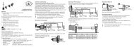
Installation5.3 Electrical Connections5.3.1 Connection PossibilitiesSource Cable/power supply InterfacePC2300-x/SUB-D and PC2300-0,5/YPC2300-x/C-Box/RJ45EtherCATPC2300-x/OE orPC2300-x/SUB-Dand PC2300-0,5/YC-BoxPS 2020PC2300-x/OERS422-USB ConverterPC2300-x/IF2008 (IF2008-Y) orPC2300-x/SUB-D and PC2300-0,5/YPC2300-x/IF2008IF2004/USBEthernetSPSand IF2008-Y-adaptercableEthernetUSBIF2008PCFig. 12 Connection examples on ILD 2300PC2300-x/CSPCSP 2008Sensor supply isdone by peripheral<strong>optoNCDT</strong> 2300Page 31
InstallationThe different periphery devices can be connected by the illustrated connection cables to the 14-pin sensorplug, see Fig. 14. The devices PCI interface card IF2008, 4-way converter IF2004/USB and universal controllerCSP2008 also supply the operating voltage (24 V DC) of the sensor via the appropriate connection cable.Peripheral Sensor channels InterfaceRS422-USB converteroneIF2004/USBfourIF2008, PCI interface card fourRS422CSP2008, universal controller twoExtension terminal CSP2008 twoEthernet (network, PC)anyEtherCAT (master)anyEthernet / EtherCATPLC, ILD2300 or the like --- SynchronizationSwitch, button, PLC or the like --- Switching input laser On/OffFig. 13 Max. sensor channels on the peripheral devices<strong>optoNCDT</strong> 2300Page 32
Installation5.3.2 Supply VoltageNominal value: 24 V DC (11 ... 30 V, max. 150 mA).Switch on the power supply unit, once wiring is completed.11 ...30 VDCConnect the inputs “1“ and “2“ at the sensor with a 24 V voltage supply.12ILD 2300SensorPinPC2300-x/YColorSupply1 white +U B2 brown GroundUse the supply voltage for measurement instrumentsonly and not for drive units or similar sources of pulseinterference at the same time. MICRO-EPSILONrecommends using an optional available power supplyunit PS2020 for the sensor.Fig. 14 Connection of supply voltage5.3.3 Laser onThe measuring laser on the sensor is activated via an optocoupler input. This is advantageous if the sensorhas to be switched off for maintenance or similar. Switching can be done with a transistor (for example opencollector in an optocoupler) or a relay contact.iIf pin Pin 3 is not connected with +U Band Pin 4 is not connected with ground, the laser is off. The wiringfor laser on/off with the supply voltage is already done in the PC2300-x/SUB-D and PC2300-0, 5/Ycables.Type 1 Type 2 PC2300-x/Y +UBwhite 1ILD 2300TTL o. U OUTappr. 5mAgreen 3HTLLaser off:U max.OUT < 0.8 VLaser on:30 V2.8 V < U OUT < 30 Vyellowbrown42GroundThere is no external resistorfor current limiting required.Connect Pin 1 with 3 and Pin2 with 4 for permanent „Laseron“.Reaction Time for Laser-On:Correct measuring data aresent by the sensor approximately1 ms after the laserwas switched on.Fig. 15 Electrical wiring for laser off<strong>optoNCDT</strong> 2300Page 33
Installation3241101112 14135 6Fig. 16 Sensor roundpin plug, view: Solderpinside male cableconnector, insulator9785.3.4 Input and OutputsSignalSensorCable PC2300-x/SUB-D 1CommentDesignation Pin15-pol. Sub-D+ U b1 Supply voltage (11 ... 30 VDC) 1Ground 2System ground for supply andground potential for RS422-level9+Laser on/off 3 Optocoupler input, potential-free2Laser off: U E≤ 0,8 V (Low)- Laser on/off 4 Laser on: 2,8 V ≤ U E≤ 30 V (High)10Sync-in/out 2 5Synchronous- respectively trigger signals, symmetrically,RS422-Pegel, terminating resistor3/Sync-in/out 2 6120 Ohm switchable, input or output selecteddepending on the synchronization mode11RxD-RS422 7 Serial input RS422, symmetrically,4/RxD-RS422 8 Internally terminated with 120 Ohm12TxD-RS422 95Serial output RS422, symmetrically/TxD-RS422 10 13Tx - Ethernet 116Ethernet output, potential-free/Tx - Ethernet 12 14Rx - Ethernet 137Ethernet input, potential-free/Rx - Ethernet 14 15Screen Housing No galvanic connection to ground Housing1) You will find more cables in appendix.2) In trigger operation, see Chap. 7.6.1, the input is used for triggering.Plug connector: ODU MINI-SNAP, 14-pol., series B, dimension 2,code F, IP 68.<strong>optoNCDT</strong> 2300Page 34
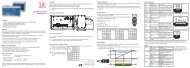
PInstallation5.3.5 EthernetTo connect the sensor via the Ethernet interface the internet protocols TCP and UDP are used. This requiresgenerally a PC with a web browser such as Mozilla Firefox and a free Ethernet interface or a network connection.Standard protocol is TCP/IP.Connect the sensor to a PC via a direct Ethernet connection (LAN) or Switch (Intranet). Thereforeuse a LAN cable with RJ-45-male connectors and the optionally available cables PC2300-x/SUB-D andPC2300-0.5/Y.PC2300-0.5/YPatch cableaser o fIn angeMid angeErrorEthe CAT E hernetRUNP wer onERR<strong>optoNCDT</strong>PC2300-x/SUB-DL serstr hluni ht in den trahl b i kenL ser Kl sse 2nach D N N 60825 1: 2008-05P = 1 mW; P = 1 2 mW; t=0 5. .542 µsF=1,5 . 50 kHz; =670 nmPS2020NL230 VACPEFig. 17 Measurement setup with Ethernet connection<strong>optoNCDT</strong> 2300Page 35
PPInstallation5.3.6 EtherCATThrough the Ethernet connection, the sensor can also be integrated into an EtherCAT environment.Connect the sensor to a 2-port EtherCAT junction. Use a LAN cable with RJ-45-male connectors and theoptionally available cables PC2300-x/SUB-D and PC2300-0.5/Y.PC2300-0.5/YPatch cableaser o fIn angeMid angeErrorEthe CAT E hernetRUNP wer onERRPC2300-x/SUB-DRunEtherCAT/CSP2008<strong>optoNCDT</strong>X1L serstr hlungi ht in den trahl b i kenL ser Kl sse 2nach D N N 60825 1: 2008-05P = 1 m ; P = 1 2 mW; t=0 5. .542 µsF=1,5 . 50 kHz; =670 nmRS422extension terminalPC2300-x/CSPPS2020NLX2BECKHOFF EK1122230 VACPE2-Port-EtherCATjunctionPC/Notebookaser o fIn angeMid angeErrorEthe CAT E hernetRUNP wer onERREtherCAT/CSP2008<strong>optoNCDT</strong>L serstr hlungi ht in den trahl b i kenL ser Kl sse 2nach D N N 60825 1: 2008-05P = 1 m ; P = 1 2 mW; t=0 5. .542 µsF=1,5 . 50 kHz; =670 nmFig. 18 Measurement setup with EtherCAT connection<strong>optoNCDT</strong> 2300Alternatively, a connection via the RS422 extension terminal and the cable PC2300-x/CSP is possible.Both are available as optional accessories.Page 36
Installation5.3.7 Connector and Sensor CableNever bend the sensor cable by more than the bending radius of 90 mm.The sensor comes with a permanently mounted connection cable of 0.25 m in length. A 3 m, 6 m or 9 m sensorcable has to be attached to the connection cable.MICRO-EPSILON recommends the use of the standard sensor cable in the appendix, see Chap. A 1, with achain-type cable capability.The connector and the cable component are marked with red markings which have to be aligned oppositeeach other before connection. In addition, they come with guidance grooves to prevent them from beingwrongly connected. To release the plug-in connection, hold the plug-in connector on the grooved grips (outersleeves) and pull apart in a straight line. Pulling on the cable and the lock nut will only lock the plug-in connector(ODU MINI-SNAP FP - lock) and will not release the connection.Avoid subjecting the cable to excessive pull force. If a cable of over 5 m in length is used and it hangsvertically without being secured, make sure that some form of strain-relief is provided close to the connector.Never twist the connectors in opposite directions to one another when connected.Connect the cable shield to the potential equalization (PE, protective earth conductor) on the evaluator(control cabinet, PC housing) and avoid ground loops.Never lay signal leads next to or together with power cables or pulse-loaded cables (e.g. for drive unitsand solenoid valves) in a bundle or in cable ducts. Always use separate ducts.Recommended strand cross-section for self-made connection cables: ≥ 0.14 mm² (AWG 25)Disconnect or connect the D-sub connection between RS422 and USB converter, when the sensor isdisconnected from power supply only.i<strong>optoNCDT</strong> 2300Page 37
Operation6. Operation6.1 Getting Ready for OperationInstall and assemble the <strong>optoNCDT</strong> 2300 in accordance with the instructions set out, see Chap. 5.Connect the sensor with the indicator or monitoring unit and the power supply.The laser diode in the sensor can only be activated if at the input „Laser on/off“ Pin 1 is connected to 3 andPin 2 to 4, see Chap. 5.3.3.Once the operating voltage has been switched on the sensor runs through an initialization sequence. Thisis indicated by the momentary activation of all the LEDs. Once initialization has been completed, the sensortransmits a „->“ via the serial interface. The initialization takes up to 10 seconds. Within this period, the sensorneither executes nor replies to commands.To be able to produce reproducible measurements the sensor typically requires a start-up time of 20 minutes.If the “state“ LED is not on, this means that--either there is no operating voltage or--the laser has been switched off.6.2 Operation via EthernetIn the sensor, dynamic Web pages are created that contain the current settings of the sensor and the periphery.The operation is only possible as long as an Ethernet connection to the sensor exists.6.2.1 PreconditionsYou need a web browser (for example Mozilla Firefox or Internet Explorer) on a PC with a network connection.To support a basic first commissioning of the sensor, the sensor is set to a direct connection.The parallel operation using a web browser and ASCII commands is possible; the last setting applies. Rememberto save the settings.<strong>optoNCDT</strong> 2300Page 38
OperationDirect connection to PC, sensor with static IP (Factory setting)NetworkPC with static IP PC with DHCP Sensor with dynamic IP, PC with DHCPConnect the sensor to a PC via a direct Ethernet connection (LAN). Usean optionally available cable PC2300-x and PC2300-0.5/Y.Now start the SensorFinder.exe program.You will find this program on the providedCD.Click the button Find sensors. Selectthe designated sensor from the list. Inorder to change the address settings,click the button Change IP-Address.••Address type: static IP address••IP address: 169.254.168.150 1••Subnet mask: 255.255.0.0Click the button Change, to transmit thechanges to the sensor.Click the button Start browser toconnect the sensor with your defaultbrowser.1) Requires that the LAN connection on thePC uses, for example, the following IP address:169.254.168.1.Wait until Windows has establisheda network connection(Connection with limited connectivity).Now start the SensorFinder.exeprogram. You willfind this program on theprovided CD.Click the button Findsensors. Select the designatedsensor from thelist.Click the button StartBrowser button to connectthe sensor with yourdefault browser.Connect the sensor to a switch (Intranet). Usean optional available cable PC2300-x undPC2300-0.5/Y.Enter the sensor in the DHCP / register the sensorin your IT department.The sensor gets assigned an IP address from yourDHCP server. You can check this IP address with theSensorFinder.exe program.Now start the SensorFinder.exe program.You will find this program on the provided CD.Click the button Find sensors. Select thedesignated sensor from the list.Click the button Start browser, to connectthe sensor with your default browser.Alternatively: If DHCP is enabled and the DHCPserver is linked with the DNS server, an access ispossible on „ILD2300_SN01234567“ („01234567“Serial number of your sensor)Start a web browser on your PC. Type„ILD2300_Serial number“ in the address bar ofyour web browser.6.2.2 Access via EthernetOnce the sensor is provided with an IP address, which is valid for your environment and it is known to you, you can connect the sensorwith a web browser, see Chap. 6.2.1.<strong>optoNCDT</strong> 2300Page 39
OperationInteractive websites for programming the sensor now appear in the web browser.The parallel operation using a Web browser and ASCII commands is possible; the last setting applies. Rememberto save the settings.Programming the sensor. In the top navigationbar other auxiliary functions (settings, videosignal, etc.) are available. All settings in thewebsite will be immediately executed in thesensor after pressing the button Apply.Fig. 19 First interactive website after selectionof the IP address.The look of the website may change depending on the features. Each page contains descriptions of theparameters and so tips for filling out the web site.Further sub-menus, such as measuring rateand triggering, are available via the left navigationof the website.iAfter programming all the settings areto be stored permanently in a set ofparameters. The next time you turn onthe sensor they are available again.<strong>optoNCDT</strong> 2300Page 40
Operation6.2.3 Measurement Presentation via Web BrowserFor graphical description of the measuring results “Java“ must be enabled and updated in the browser.Start the measurement value display (Measurement) in the horizontal navigation bar.iFig. 20 Web interfaceIf you leave the diagram display in a separate tab or window of the browser running, you do not have torestart the description each time.Click the button Start, for starting the display of the measurement results.The demo can only be started, if a possible saving of measured values is completed via Ethernet, becauseonly one of two features can be active via Ethernet.<strong>optoNCDT</strong> 2300Page 41
OperationFig. 21 Display of measurement results<strong>optoNCDT</strong> 2300Page 42
Operation6.2.4 Video Signal via Web BrowserWith the presentation of raw and filtered video signals the effects of the adjustable video filter (video averaging)are shown. The raw signal corresponds to the signal of the detector.The filtered signal is--independent of the video averaging settings in the settings menu,--preprocessed through the first signal processing stage.There is no linear relationship between the position of the peaks in the video signal and the output measurementvalue.<strong>optoNCDT</strong> 2300Fig. 22 Display of video signalsPage 43
Operation6.3 Programming via ASCII CommandsAs an added feature you can program the sensor via an ASCII interface, physically RS422 and / or Ethernet.This requires, that the sensor must be connected either to a serial RS422 interface via a suitable interfaceconverter, see Chap. A 1, or a plug-in-card to a PC / PLC. In addition, the Ethernet interface can be used via asuitable program, for example Telnet.Pay attention in the programs used to the correct RS422 default setting or a valid Ethernet address.Once connected, you can transfer the commands from the appendix, see Chap. A 6, via the terminal or Telnetto the sensor.6.4 Timing, Measurement Value FluxThe sensor operates internally with real time cycles in a pipeline mode:1. Exposure: Charging the image detector in the receiver (measurement),2. Reading: Reading out of the imaging device and converting into digital data,3. Computing (2 cycles),4. Synchronous output.Each cycle takes about 20 μs at a measuring rate of 49.02 kHz. The measured value N is available after eachcycle with a constant lag of four cycles in respect to the real time event. The delay between the input reactionand the output signal is therefore about 60 µs up to 80 μs. The processing of the cycles occurs sequentiallyin time and parallel in space (pipelining). This guarantees a constant real time data stream.<strong>optoNCDT</strong> 2300Page 44
OperationMeasurement programDiffusedisplacement measurementDirectdisplacement measurementDirectthickness measurementLinearization diffusemeasurement arrangement,laser power 1 mWLinearization direct measurement arrangement,laser power switchableRefractive index correctionDisplacement measurementhighest peak, peak with the largest surface, 1. peakAverageselected displacementSetting masters / zeroingselected peakStatistics calculation fordisplacementThickness measurementthickness, 1. & 2. peakAveragethickness & 1. & 2. displacementSetting masters / zeroingthicknessStatistics calculation forthicknessDisplacement measurement ondiffuse reflecting targetsDisplacement measurementon direct reflecting targetsThickness measurement on directreflecting transparent targetsGrey shadedfields require aselection.Fig. 23 Adjustment possibilities of the <strong>optoNCDT</strong> 2300ValueDark-borderedfields require youto specify a value.<strong>optoNCDT</strong> 2300Page 45
Control Menu, Set Sensor Parameter7. Control Menu, Set Sensor Parameter7.1 Preliminary Remarks to the AdjustmentsYou can program the <strong>optoNCDT</strong> 2300 simultaneously in two different ways:--using a web browser via the sensor Web interface--ASCII command set and a terminal program via RS422 or Ethernet (Telnet). Received measurement valuesare displayed with binary character.iIf you do not save the programming permanently in the sensor, you lost the settings after turning off thesensor.7.2 Overview ParameterThe following parameters can be set or change in the <strong>optoNCDT</strong> 2300, see Fig. 20 menu Settings.LoginDefault settingsData outputMeasurement controlParameter, extras7.3 Login, Change User LevelEntering a password, change user levelMeasurement program, measurement frequency, averaging, behaviorin the case of error, setting zero/setting masters and material database for thickness measurementSelection and setting of digital interface, data to be emitted, underscanningTriggering, synchronization of sensorsLoading/saving parameter- and interface settingsMenu language, factory settingThe assignment of a password prevents unauthorized changing of settings on the sensor. When delivered,the password protection is not enabled. The sensor operates in the user level “expert“. The password protectionshould be enabled after configuration of the sensor. The default password for the expert level is “000“.The default password or a user-defined password is not changed by a software update. The expertpassword is independent of the setup and is therefore not together loaded or saved with the setup.i<strong>optoNCDT</strong> 2300Page 46
Control Menu, Set Sensor ParameterThe following functions are available for the user:UserExpertPassword required no yesLooking settings yes yesChanging settings, changing password no yesMeasurement value, looking video signal yes 1 yesScaling diagrams yes yesSetting factory setting no yesFig. 24 Rights in the user hierarchyLoginYou are currently logged in as User.PasswordType the default password “000“ or a userdefinedpassword in the Password fieldand confirm with login.Change with a click on the Logout buttonin the mode user.LoginFig. 25 Change in the expert user levelThe user management allows you to assign a custom password in the “expert“ mode.Password Value Case-sensitive rules are observed for all passwords. Numbers are allowed.Special characters are not allowed.User level whenswitching onUser /ExpertSpecifies the user level, with which the sensor starts after the re-starting.For this purpose, MICRO-EPSILON recommends the selection user.1) Only if there is no measurement output via a different interface. Otherwise you must be logged in expertmode.<strong>optoNCDT</strong> 2300Page 47
fch n d n h b k na e a e 20 2 2 08 02 0 2 µ0 0N NControl Menu, Set Sensor Parameter7.4 Default Settings7.4.1 Measurement ProgramSettings for the measurement programs in the <strong>optoNCDT</strong> 2300.MeasurementsetupPeak to be measureddiffuse reflection /direct reflection /displacement measurement /direct reflection thicknessmeasurementfirst peak /highest peak /widest peakDisplacement measurement by diffuse reflection; sensorevaluates the reflected stray light. Displacement or thicknessmeasurement by direct reflection; Sensor evaluatesthe light, which is reflected at the target surface. The sensoruses the first both peaks for thickness measurement.Defines, which signal is used for the evaluation in the linesignal. First Peak: Nearest peak to sensor. Highest peak:Standard, peak with the highest intensity.Widest Peak: Signal with the largest area, use by smalladjacent faults100 %nearSensorfaraserIn angeMid anger orE he CAT E he netRUNP we onERR<strong>optoNCDT</strong>Lase f Eth rCAT Et ernetn rangeRUNMi rangeP wer onEr orERR<strong>optoNCDT</strong>N bP = W P = W == H =50 %FirstpeakHighestpeakWidestpeakDiffuse reflection Direct reflection 129257 384 512ValueGrey shadedfields require aselection.Dark-borderedfields require youto specify a value.7.4.2 Measuring RateSetting for the measuring rate in the <strong>optoNCDT</strong> 2300 and so the data rate.Measuring rate 1.5 / 2.5 / 5 / 10 / 20/ 30 / 49.02 kHzDark and shining objects may require a slower measuring rate. Thecontrol do not expose longer than the measuring rate allows. Themeasurement range of the sensor is reduced at 49.02 kHz.<strong>optoNCDT</strong> 2300The measuring rate defines the number of measurements performed by the sensor per second.Page 48
Control Menu, Set Sensor ParameteriSynchronized sensors must always be set to the same measuring rate. Use a high measuring rate forlight colored and matt objects to be measured. Use a low measuring rate for dark or shiny objects to bemeasured (e.g. surfaces covered in black lacquer), for better measurement results.At a maximum measuring rate of 49.02 kHz the CMOS element is exposed 49.020 times per second.The lower the measuring rate, the longer the maximum exposure time. The real-time control of the sensorreduces the exposure time in dependency on the amount of light hitting the CMOS element and thereforecompensates for reflection changes at the same time, e.g. caused by imprints on the surface of the objectbeing measured.The output rate gives the actual number of measurement values at the sensor output per second. The maximumoutput rate can never exceed the measuring rate. The maximum frequency of the Ethernet interface isdependent on the number of output values.RS422 specificity: To detect a data loss on the receiver side, the sensor sends in this case a runtime error. Ifnot all data can be output via RS422, error codes are issued in the next record.Calculation of the output rate using the RS422 serial interface:Abbreviations used:Output rate = Measuring rate / n * ODRn = Partial factorint =Integral part of ( )b = Byte/measurement value (binary format b=3)MF = Measuring rate [Hz]n = int (b * 11 * MF / BR) + 1BR = Baud rate [Baud]ODR = Output data rateFig. 26 Relation of measuring rate to output rate on the RS422<strong>optoNCDT</strong> 2300Page 49
Control Menu, Set Sensor ParameterCalculation of the data rate / refresh rate:DR [kSa/s] = (MR / a * (Td/Tn)) / ODRAbbreviations used:DR = Data rateMR = Measuring rate [Hz]a = 1, simultaneous synchronizationa = 2, alternating synchronization (master resp. slave)Td = Trigger pulse durationTn = Trigger non-pulse periodODR = Output data rateFig. 27 Ethernet and RS422 data rate in accordance with the channel bandwidth<strong>optoNCDT</strong> 2300Page 50
Control Menu, Set Sensor Parameter7.4.3 Averaging, Error Processing, Spike Correction and StatisticsValueGrey shadedfields require aselection.Dark-borderedfields require youto specify a value.<strong>optoNCDT</strong> 2300Video averaging No averaging /Recursive 2 / 4 / 8Moving 2 / 3 / 4Median 3Averaging of measurementNo averagingvalueThe video averaging is effected before thecalculation of the displacement or thickness.Recommended for very small peaksrespectively to receive more valid data.Moving N values 2 / 4 / 8 ... 128 Value Indication of averaging mode. The averagingnumber N indicates the number ofRecursive N values 2 ... 32768 Valueconsecutive measurement values to beMedian N values 3 / 5 / 7 / 9 Value averaged in the sensor.Error processing Error output, no measurement value Sensor emits error value.Hold last value 0 ... 1024 Value If no valid measurement value is determined,the last valid value can be hold fora certain period, that is, output repeatedly.The last valid value is kept indefinitely at„0“.Spike correction NoYesEvaluationlength1 - 10Value This filter removes individual very highspikes from a relatively constant course ofmeasurement value.Max. tolerance Valuerange (mm)Smaller spikes are preserved.0 - 100Number of Valuecorrected value1 - 100Statistics 2 / 4 / 8 / 16 ... 16384 Beyond a certain number of measurementvalues the statistical values minimum, maximumand peak-to-peak are determinedand output.Page 51
Control Menu, Set Sensor ParameterAn averaging in two different ranges of the signal processing is possible in the <strong>optoNCDT</strong> 2300.--Averaging in video signal--Averaging of measurement valuesThe averaging is recommended for static measurements or slowly changing values.In the sensor, one after another following video curves are averaged pixel by pixel. The effect of different settingscan be observed in a second curve “Filtered signal“ in the web browser in the category video signal.7.4.3.1 Measurement AveragingThe averaging of measurement values is effected after the calculation of the displacement and thicknessvalues prior to the output via the interfaces.The purpose of averaging is to:--Improve the resolution--Eliminate signal spikes or--„Smooth out“ the signal.Averaging has no effect on linearity.In completion of the measuring cycle the internal average is calculated again.The preset average value and the number of averaging are to save in the sensor, so that they remainafter switching off.iAveraging does not affect the measuring rate or data rates in digital measurement value output. The averagingnumbers can also be used if programmed via the digital interfaces. The sensor <strong>optoNCDT</strong> 2300 is suppliedex factory with the default setting „Median 9“, that is, averaging with Median and 9 measurements.Moving averageThe selected number N of successive measurement values (window width) is used to generate the arithmeticaverage value M glon the basis of the following formula:<strong>optoNCDT</strong> 2300Page 52
Control Menu, Set Sensor ParameterNMV = Measurement value,MV (k)N = Averaging number,k=1M gl =k = Running indexNM = Averaging value respectively output valueglMode:Each new measurement value is added and the first (oldest) measurement value from the averaging process(from the window) taken out again. This results in short transient recovery times for jumps in measurementvalues.Example with N = 4... 0, 1, 2, 2, 1, 3... 1, 2, 2, 1, 3, 4Measurement values2, 2, 1, 34= M (n)gl2, 1, 3, 44= M (n+1)glOutput valueCharacteristics:When moving averaging in the <strong>optoNCDT</strong> 2300 only powers of 2 for the averaging number N are allowed.Range of values for number of average N is 1 / 2 / 4 / 8 ... 128.Recursive AverageFormula:M (n) =rekMode:MV(n)+ (N-1) x Mrek (n-1)NMV = Measurement value,N = Averaging number,n = Measurement value indexM = Averaging value respectively output valuerekEach new measurement value MV(n) is added, as a weighted value, to the sum of the previous measurementvalues M rek(n-1).<strong>optoNCDT</strong> 2300Page 53
Control Menu, Set Sensor ParameterCharacteristics:The recursive average permits a high degree of smoothing of the measurement values. However, it requiresextremely long transient recovery times for steps in measurement values. The recursive average shows lowpass behavior. Range of values for number of average N is 1 ... 32768.MedianThe median is generated from a pre-selected number of measurement values.Mode:To do so, the incoming measurement values (3, 5, 7 or 9 measurement values) are resorted again after everymeasurement. The average value is then given as the median. In generating the median in the sensor, 3, 5, 7or 9 measurement values are taken into account, that is, there is never a median of 1.Characteristics:This averaging mode suppresses individual interference pulses. The measurement value curve is notsmoothed to a great extent.Example: Average from five measurement values... 0 1 2 4 5 1 3 Sorted measurement values: 1 2 3 4 5 Median (n)= 3... 1 2 4 5 1 3 5 Sorted measurement values: 1 3 4 5 5 Median (n+1)= 47.4.3.2 Spike CorrectionThis special form of filtering is used to remove very high spikes from a relatively constant course of measurementvalues, though while retaining any smaller spikes. A median would remove all the spikes.The assessment of whether a measurement is a spike (outlier) is based on the mean of a particular numberof previous valid readings. The permissible deviation from the next value is calculated using the tolerancerange. If the new measured value deviates too much, it will be corrected to the previous value. A maximumnumber of consecutive measured values to be corrected must also be stated.Attention: In the event of several consecutive spikes (outliers), the previous corrected value is used in thecorrection of the following measured value. Use this function only in appropriate applications. Improper usecan lead to a distortion of the measured value sequence! Check the possible impact of a changed measuredvalue sequence on the measuring environment and subsequent controllers/systems.<strong>optoNCDT</strong> 2300Page 54
Control Menu, Set Sensor ParameterThis function acts the same way on all output distances; the differences (thicknesses) are calculated on thebasis of the corrected distances.--x Evaluation length. Number of previous measured values to be assessed (max. 10).--y Max. tolerance range (mm); the spike (outlier) correction comes into play when the value is not met or isexceeded--z Number of corrected value (max. 100)Example: x = 3 / y = 0.05 / z = 110,00109,959,909,859,809,759,709.839.85xEvaluationlength9.88Number ofcorrectedvalue9.899.85Max.tolerancerange9.86x1 2 3 4 5 6 7 8 9 109.88Averagevalue9.752y9.77zFig. 28 Correction of measuring values<strong>optoNCDT</strong> 2300Page 55
Control Menu, Set Sensor Parameter7.4.3.3 Statistical valuesThe <strong>optoNCDT</strong> 2300 can deduce the following statistical values from the result of measuring or the calculating:ValueGrey shadedfields require aselection.Dark-borderedfields require youto specify a value.MINMAXPEAK2PEAKMinimumMaximumPeak-to-peak value(Range)SignalPeak-to-peakFig. 29 Statistical values and evaluation cyclein evaluation cycleMinimumPeak-to-peakEvaluation cycleMaximumThe statistical values are calculated from the measurement values within the evaluation cycle. With the commandRESET STATISTICS, a new evaluation cycle (storage period) will be initiated. At the beginning of a newcycle, the old statistical values are deleted.Time<strong>optoNCDT</strong> 2300Page 56
Control Menu, Set Sensor Parameter<strong>optoNCDT</strong> 23007.4.4 Setting Zero and MastersBy zeroing and mastering you can set the measurement value to a set point in the measuring range. The outputrange is moved thereby. This function makes sense, for example, for several adjacent measuring sensorsor in the case of the thickness and planarity measurement.Master value in mm Value Data, for example of the thickness, of a master piece.Value range max. – 2 x measuring range up to + 2 x measuring rangeSetting masters is used to compensate mechanical tolerances in the measurement setup of the sensors or toadjust the temporal (thermal) changes in the measurement system. The masters measurement, also a knownas the calibration measurement, is given a set point.The value which is given during measurement on the sensor output of the “mastering object“ is the “mastervalue”. The zero-setting is a characteristic of the mastering, because here the master value is „0“.6487632760Output characteristic643x m0 % Measuring rangeOutput characteristic after mastering100 %Fig. 30 Characteristic for masteringiWhen mastering the sensor‘s characteristic is parallel displaced. Thedisplacement of the characteristic curve reduces the usable measurementrange of the sensor the further the master value is away from the masterposition.Sequence for mastering /Setting zero:Bring target and sensor in the desired position together.Send the master command.The master command waits for 2 seconds on the next measurement valueand masters it. If no measurement value is received within this time, forexample by external triggering, the command returns with the error “E32Timeout“ back.After the mastering, the sensor gives new measurement values, related tothe master value. The non-mastered condition applies by means of a resetwith the button Reset master value .“Setting masters“ or “Setting zero“ requires that a target is within the measurement range “Settingmasters“ or “Setting zero“. “Setting masters“ and “Setting zero“ has an influence on the digital outputs.Page 57
Control Menu, Set Sensor Parameter7.4.5 Material Data BaseYou can save the optical refractive indices of various materials in the sensor, that can be used for the measurementof direct reflection. The material database of the condition at delivery can be recovered by loadingthe factory settings. Up to 20 materials can be stored in the material database.Material name Value General information on materialMaterial description ValueRefractive index n Value Optical refractive index of materialE er tIn a gMidrangeErrorERR<strong>optoNCDT</strong>LaserstrahlungNicht in den Strahl b ickenLaser Klasse 2nach D N N 60825-1: 2008-05P = 1 mW; P = 1,2 mW; t=0 5. .542 µsF=1 5. .50 kHz; =670 nm0PFor measurements on transparent targets, such asfilms, it is due to the refractive index to smaller measurementvalues than it is actually the case.Is the respective material specified now for the measurement,the refractive index runs into the calculationand so the sensor delivers the correct result.Grey shadedfields require aselection.ValueDark-borderedfields require youto specify a value.<strong>optoNCDT</strong> 2300Page 58
Control Menu, Set Sensor Parameter7.5 Data Output7.5.1 Digital InterfacesSelection of digitalinterfacesWeb diagram /Ethernet measurement transmission /RS422Data selection Distance / Statistics Min / Statistics Max /Statistics peak-to-peak / Exposure time /Intensity of distance value / Error status /Measured value counter / Time stamp /Trigger counter / TemperatureSettingsEthernetIP settings ofthe base unitSettings of theEthernet measurementvaluetransmissionAddress type Static IP address /DHCPIP address ValueGateway ValueSubnet mask ValueTransmission Client / ServertypeProtocolIP addressPCP/IP / UDP/IPValueDecides via the used interface for measurement output.A parallel measurement output via multiple channels isnot possible.The data which are provided for the transmission are toactivate with the checkbox.When using a static IP address, values for IP address,gateway and subnet mask are to set; and this not applieswhen using DHCP.The sensor as server provides the measurement valuesat the indicated port or sends them connection-orientedas client to the indicated client. The measurement valueserver is the destination of the measurement values andcan be a PC or a PLC in the network. PC for programming/demo programming are not measurement valueserver.Port Value Setting the port on the measurement value server;SettingsBaud rate 9.6 / 115.2 / 230.4 ... / 4000 kBps Transmission rate with binary data format.RS422Ethernet/EtherCAT Operation mode after start Ethernet/EtherCAT<strong>optoNCDT</strong> 2300Page 59
Control Menu, Set Sensor Parameter7.5.2 Output Data RateData reduction Value Instructs the sensor, which data are excluded from the output,and thus the amount of transferred data is reduced.Reduction appliesforRS422 / EthernetThe interfaces, which are provided for the sub-sampling, are tobe selected with the checkbox.You can reduce the measurement output in the sensor if you set the output of every nth measurement values in the Web interface orby command. The reduction value n can range from 1 (each measurement value) to 3.000.000. This allows you to adjust slower processes,such as a PLC, to the fast sensor without having to reduce the measuring rate.7.6 Measurement Control7.6.1 TriggeringSelected mode Level triggering Measurement value inputMeasurement value outputEdge triggering Measurement value inputMeasurement value outputTermination Sync/Trig-inputSoftware triggeringNo triggeringCheckboxMeasurement value inputMeasurement value outputMeasurement valueoutput atStart of measurementvalue output withNumber of measurementvaluesNumber of measurementvaluesLevel low / Level highFalling edge / Rising edgeValueValue“0“ stop triggering“1 ... 16382“ values per trigger“16383“ continuous data output“0“ stop triggering“1 ... 16382“ values per trigger“16383“ continuous data outputCheckbox activates the terminating resistor for line matching.The <strong>optoNCDT</strong> 2300 measurement output is controllable through an external signal. Triggering does not influence the measuring raterespectively the timing, see Chap. 6.4, so that between the trigger event (level change) and the output reaction always lie 4 cycles + 1cycle (Jitter). <strong>Micro</strong>-<strong>Epsilon</strong> recommends the abdication of data reduction, for example, by sub-sampling when the triggering is used.The measurement value output rate in trigger mode can be controlled with the edge as well as the level of the trigger signal.<strong>optoNCDT</strong> 2300Page 60
Control Menu, Set Sensor ParameterImplemented trigger conditions:Level triggering with high level / low level. Continuous measurementoutput, as long as the selected level is applied.Then stops the data output. The pulse duration must be atleast one cycle time. The subsequent break must also be atleast one cycle time.Fig. 31 Low trigger level (above) and digital output signal (below)U ID 0ttEdge triggering with rising or falling edge. After the triggerevent the sensor outputs the preset number of measurementvalues or starts a continuous measurement value output. Thepulse duration must be 5 μs at least.Fig. 32 Trigger edge LH (above) and digital output signalU ID 0ttSoftware triggering. Starts the measurement value output,when a software command comes. The trigger time isdefined more inaccurately. After the trigger event the sensoroutputs the preset number of measurement values or startsa continuous measurement value output. If “0“ is selectedfor the number of measurement values, the sensor stops thetriggering and the continuous value output.The required signal levels comply to the EIA-422 specification. so that only driver circuits with RS422 outputare recommended for triggering. The difference between both input signals Trig+ (pin 5) and Trig- (pin 6)must be according to amount greater than 400 mV.The sensor detects a high level, if the voltage on Trig+ is greater than on Trig-. The <strong>optoNCDT</strong> 2300 containsa terminating resistor between pin 5 and 6 for line matching which can be connected via ASCII command.<strong>optoNCDT</strong> 2300Page 61
Control Menu, Set Sensor ParameterThe synchronous inputs are used for external triggering. Sothe sensors can alternatively be synchronized or triggered.The change between synchronization (default setting) andtriggering is possible with the Web interface or ASCII command.Trigger source can be, for example, an encoder withRS422-level or a level converter which resets the TTL / HTLsignals in RS422 level. <strong>Micro</strong>-<strong>Epsilon</strong> recommends the levelconverter SU4-x from LEG Industrie-Elektronik, see appendix.Maximum trigger rate £ 0.4 * measuring rateTriggersourceU I56GNDFig. 33 Trigger wiring2ILD 2300Signal Sensor Extension cable PC2300Pin Fig. 34 Sensor round15-pol. Sub-D1 1029 connector, view onGND 2113 12 14 solder pin side male913Trigger-in/out 5 47 cable connector35 6/Trigger-in/out 6 118Grey shadedfields require aselection.ValueDark-borderedfields require youto specify a value.<strong>optoNCDT</strong> 2300Page 62
Control Menu, Set Sensor Parameter7.6.1.1 Signal Processing without TriggerVideo signalVideo averagingMaskingDistance calculationError identificationRefractive index correctionSpike correctionDifference / ThicknessMeasurement averagingnoError loggingFound error?yesRelative measurements afterZeroing / MasteringStatisticsHold last valueAAData reductionGetValueData output<strong>optoNCDT</strong> 2300Page 63
Control Menu, Set Sensor Parameter7.6.1.2 Signal Processing -Value Output TriggerMeasurement values are calculatedcontinuously and independentlyof the trigger event.A trigger event simply triggersthe value output via a digitalinterface. Therefore, any valuesmeasured immediately beforethe trigger event are included incalculating mean values (averages)or statistics.Video signalVideo averagingMaskingDistance calculationError identificationRefractive index correctionTriggerSpike correctionnoError loggingFound error?Trigger processingDifference / ThicknessyesMeasurement averagingTrigger signal?noRelative measurements afterZeroing / MasteringyesData reductionStatisticsHold last valueGetValueData outputNo data output<strong>optoNCDT</strong> 2300Page 64
Control Menu, Set Sensor Parameter7.6.1.3 Signal Processing- Trigger for AcquiringValuesVideo signalTriggerThe current array signal isprocessed only after a validtrigger event, and it is usedto calculate the measurementvalues. The measurementvalues are then forwarded forfurther calculation (e.g. averagingor statistics) and foroutput via a digital interface.When calculating averagesor statistics, measurementvalues recorded immediatelybefore the triggerevent cannot be included;instead older measurementvalues are used, which wererecorded during previoustrigger events.Video averagingMaskingDistance calculationError identificationRefractive index correctionSpike correctionDifference / ThicknessnoTrigger processingTrigger signal?yesError loggingFound error?yesnoMeasurement averagingRelative measurements afterZeroing / MasteringAData reductionStatisticsGetValueHold last valueAData outputNo data output<strong>optoNCDT</strong> 2300Page 65
Control Menu, Set Sensor Parameter7.6.1.4 Signal Processing -Trigger for Outputting all ValuesThis setting acts the same as anyselected trigger type; it supportsthe same trigger behavior settingsas any other trigger type.The difference is that the triggersettings do not affect signalprocessing. Instead, trigger dataare transferred using Bit 15 of thestatus word.Video signalVideo averagingMaskingDistance calculationError identificationRefractive index correctionTriggerTrigger processingInput trigger?Spike correctionnoError loggingFound error?yesDifference / ThicknessMeasurement averagingyesTriggerStateRelative measurements afterZeroing / MasteringStatisticsHold last valueData reductionGetValueData output<strong>optoNCDT</strong> 2300Page 66
Control Menu, Set Sensor ParameterIn contrast to the input trigger, Bit 15 of the status word is used as a marker for a trigger event.Bit 15 == 0: no trigger event available.Bit 15 == 1: trigger event available.All trigger modes (level trigger, flank trigger, software trigger) are available.State (output all values)17, 16 15 14 ... 7 6 5 4 3 2 1 0State LED Triggeridentifier0 0 off0 1 green1 0 red1 1 yellow0 no trigger1 triggerReserved Peak is locatedbehind themeasuringrangePeak is in frontof the measuringrange (MR)not all peakswere calculated(peaks are tooclose together)there are fewerpeaks selectedas applicablethere isno peakpresentPeakends tolateIn addition to the status word, this trigger event information is also available in the trigger counter which may be requested as additionaldata via Ethernet as an alternative to the status word. For more information, see Chap. 7.6.2, see Chap. A 6.5.2.5.This instruction <strong>manual</strong> contains a number of additional helpful sections:--For data format output values, measurement value frame Ethernet, see Chap. 8.2.2--For measurement data transmission to a measurement value server, measurement value block, see Chap. 8.2.3--Appendix, for communication with the sensor, see Chap. A 6.5--For data selection optional values, see Chap. A 6.5.2.5iThe EtherCAT interface does not support the feature “signal processing – trigger to output all values“. Use Ethernet or RS422to output all measurement values via the interface and to evaluate Bit 15 of the status word in order to assign trigger events tomeasurement values.Peakstarts toearly<strong>optoNCDT</strong> 2300Page 67
Control Menu, Set Sensor Parameter7.6.2 Trigger Counter7.6.2.1 GeneralThe trigger counter is used to supplement the existing additional information in the sensor.Use one of the following for selection:--Data Selection web interface page--command OUTADD_ETHThese data are not available for the RS422 interface and in EtherCAT mode.The trigger counter consists of the following 4 elements:--trigger ID (T)--trigger event counter (TriggEventCnt)--trigger measurement value counter (TriggValueCnt)--reserved bits (r)31 30 29 28 27 26 25 24 23 22 21 20 19 18 17 16 15 14 13 12 11 10 9 8 7 6 5 4 3 2 1 0T r TriggEventCnt r TriggValueCnt7.6.2.2 Trigger ID (T)Depending on the selected trigger mode, Bit 31 will show if a trigger event is present:--T == 1: trigger event available.--T == 0: no trigger event.Use the TRIGGEROUT ALL command to specify during trigger selection that all measurement values aregoing to be transferred and that T== 1 is used to mark the trigger event. In the gaps between two triggerevents T == 0 is indicated.7.6.2.3 Trigger Event CounterThe trigger event counter counts the number of trigger events. Each trigger edge (presets LH or HL) increasesthe counter by 1. The counter has a bit width of 14 bit which are the lower 14 bits of the counter’s highpart.Use the RESETCNT command to reset the trigger event counter. The counter will be set to zero with the nexttrigger edge (preset) after processing the command.Counting range: 0 ... 16383.<strong>optoNCDT</strong> 2300Page 68
Control Menu, Set Sensor ParameterThe counter starts with 0.It follows:number of trigger events = trigger event counter + 1.An overflow occurs after 16384 trigger events, and the counter will start again at 0, where T= 1.7.6.2.4 Trigger Measurement Value CounterThe trigger measurement value counter is reset at each trigger edge (preset) and counts the number of measurementvalues within each trigger event. It follows:--for level triggers: number of measurement values within the selected trigger level--for edge triggers: from the selected trigger edge for the selected number of measurement values--for software triggers: after completing the command for the selected number of measurement valuesThe counter has a bit width of 14 bit which are the lower 14 bits of the counter’s low part.Counting range: 0 ... 16383The counter starts with 0.It follows:number of measurement values during a trigger event = trigger measurement value counter + 1.7.6.2.5 ExampleIf the number of the measuring values per trigger event is set with TRIGGERCOUNT at e.g. 10, see Chap. A6.3.3.4, so TRIGGVALUECNT would count from 0 to 9.<strong>optoNCDT</strong> 2300Page 69
Control Menu, Set Sensor Parameter7.6.2.6 FunctionHow the data output is assigned, depends on the selected trigger output.Command TRIGGEROUT TRIGGEREDTrigger signalMeasurementsTTrigger event counterTrigger measurement counter1 1 1 1 1 1 1 1 1 1 10 0 0 0 1 1 1 1 1 1 20 1 2 3 0 1 2 3 4 5 0Command TRIGGEROUT ALLTrigger signalMeasurementsTTrigger event counterTrigger measurement counter1 1 1 1 0 0 0 1 1 1 1 1 0 0 0 0 1 1 1 0 0 00 0 0 0 0 0 0 1 1 1 1 1 1 1 1 1 2 2 2 2 2 20 1 2 3 3 3 3 0 1 2 3 4 4 4 4 4 0 1 2 2 2 2<strong>optoNCDT</strong> 2300Page 70
Control Menu, Set Sensor Parameter7.6.2.7 Presets for Trigger Mode and Trigger EdgeThe preset values for trigger mode and trigger edge are applied from the selections in the web interface Settings> Trigger mode. They can also be specified using the TRIGGER,TRIGGERLEVEL, TRIGGER-COUNT commands.The following edge comes into effect after selecting the trigger counter:Trigger mode Trigger acts on wirksame TriggerflankeLevel triggeringlow levelhigh / lowhigh levellow / highEdge triggeringfalling edge high / lowrising edge low / highSoftware triggeringafter execution of the command (no time reference)<strong>optoNCDT</strong> 2300Page 71
Control Menu, Set Sensor Parameter7.6.3 SynchronizationSynchronizationmodeTermination Sync/Trig-inputMaster onMaster on alternating / Slave inNo synchronizationCheckboxUse at simultaneous synchronizationUse at alternating synchronizationCheckbox activates the terminating resistor for linematching.The synchronousconnections maynot be temporarilyconnected to theoperating voltageand / or GND.Risk of destructionof the sensor byoverloadingIf two or more <strong>optoNCDT</strong> 2300 measure against the same target, the sensors can be synchronized. The<strong>optoNCDT</strong> 2300 distinguishes between two types of synchronization.TypeUsed forSimultaneoussynchronizationAlternatingsynchronizationBoth sensorsmeasure in thesame cycleBoth sensorsmeasure alternativelyOutput rate ≤measuring rate / 2Measurement of differences (thickness, difference in height) onopaque objects. Here, Sensor 1 must be programmed as the “Master“and Sensor 2 as the “Slave“.Thickness measurements on translucent objects or measurementsof difference on closely spaced measurement points. The alternatingsynchronization requires that the lasers are switched on and offalternately so that the two sensors do not interfere with each otheroptically. Therefor one sensor is to program as “Master alternating“and one as “Slave“. There can be only one master to be connectedto a slave.Fig. 35 Characteristics of and uses for the different types of synchronizationiDo not run the sensor not synchronized. Synchronized sensors must be adjusted to the same measuringrate. Do not ever connect two masters with each other.Measuring rate [kHz] 1.5 2.5 5 10 20 30 49.02Synchronization1.43 ... 1.5 2.4 ... 2.5 4.8 ... 5 9.5 ... 10 19 ... 20 28.5 ... 30 46.6 ... 49rate [kHz]Fig. 36 Tolerances for the synchronization rates<strong>optoNCDT</strong> 2300Page 72
Control Menu, Set Sensor Parameter+-5ILD 2300Sensor 1(Master)120 Ohm+-5ILD 2300Sensor 2(Slave)120 Ohm+-5ILD 2300Sensor 3(Slave)120 Ohm6 2 6 2 6 2The signals Sync-in/out or /Sync-in/ of same polarityare connected in parallel with each other. A sensor is toprogram as a synchronous master, which supplies thesubsequent slave sensors with symmetric synchronouspulses, RS422-level. Only in the last slave sensor in thechain the terminating resistor is activated of 120 Ohm,see Chap. 7.6.3. The system grounds (pin 2) of the sensorsare to connect to each other.Signal Sensor Extension cable PC2300Pin15-pol. Sub-D1 1029GND 2 1193 12 14 Fig. 37 Sensor round13Sync-in/out 5 pin plug, view:4735 6 Solder-pin side male/Sync-in/out 6 cable connector11If you synchronize the sensor with an external signal source, the levels of the signal source have to complywith the EIA-422-spezifications. The difference between both input signals Sync+ (pin 5) and Sync- (pin 6)must be according to amount greater than 400 mV. Synchronization source may be, for example, a levelconverter, which converts TTL/HTL signals into RS422 level. <strong>Micro</strong>-<strong>Epsilon</strong> recommends the level converterSU4-1 from LEG Industrie-Elektronik. The synchronization rate is to take from the table, see Fig. 36. Pulseduration and non-pulse period have a ratio of 1:1.8Input or output is to select according to the type of synchronization.<strong>optoNCDT</strong> 2300Page 73
Control Menu, Set Sensor Parameter7.7 Loading, Saving, Extras7.7.1 Loading/Saving SettingsAll settings on sensor, for example measuring rate and averaging, can be permanently saved in application programs, so-called set ofparameters.Load /savesettingsManagesetups onPCiSetup no.: 1 / 2 / 3 ... 8 Selection of the set of parameters to be load/save. The user selects a number whenloading/saving a complete configuration. Allows fast duplicating of sets of parameters.Keep interfacesettingsCheckboxYou should load the interface settings only when the sensor is operated on differentnetworks respectively with different baud rates of the RS422 interface.Activate Button If you press Activate the upper selected set of parameters is loaded from the internalmemory of the sensor.Save setup Button The current sensor settings are stored in the selected set of parameters in the internalmemory of the sensor.Data selection fortransmissionSetup / materialdata baseA set of parameters contains settings for measuring, for example measuring rate andthe interface settings. The material data base contains refractive indices of differentmaterials.Setup no.: 1 / 2 / 3 ... 8 Selection of the set of parameters to be load/save. The user selects a number whenloading/saving a complete configuration. Allows fast duplicating of sets of parameters.Export setup Button If you press Export the download manager of your browser opens and offers to savethe setting values in a specified file “setup. meo“ in the PC.Keep interfacesettingsCheckboxYou should load the interface settings only when the sensor is operated on differentnetworks respectively with different baud rates of the RS422 interface.Browse / import Button If you press Browse ... Windows opens the selection window to select a configurationfile saved in the PC. By opening the selected file in the selection window, the path iscached. Loading the file will be effected by the Import setup button.After programming all the settings are to be saved permanently as a set of parameters, so the next time you turn on the sensorthey are available again.<strong>optoNCDT</strong> 2300Page 74
Control Menu, Set Sensor ParameterIf the settings under the selected parameter set no. are saved in the sensor, it works with the new values afterthe loading process. It is therefore not a new boot process in the sensor performed. The parameter-set whichwas saved last will be loaded when the sensor is switched on.7.7.2 ExtrasLanguage German / Language of the interactive websides.EnglishUnit mm / inch Units in the measurement representationFactory settingsOnly reset the material databaseInterface settings maintainedCheckboxCheckboxAllows to replace only the values in thematerial database.This enables to leave all the settings forthe Ethernet and the RS422 interface unchanged.<strong>optoNCDT</strong> 2300Page 75
Digital Interfaces8. Digital Interfaces8.1 Preliminary RemarksThe <strong>optoNCDT</strong> 2300 sensor has two digital interfaces, which can alternatively be used to data output butparallel to the parameterization.--Ethernet provides a quick non-real-time capable data transmission (packet-based data transfer). Measurementvalues and video data can be transmitted. The configuration of the sensor can be done via the webinterface or by ASCII commands. Furthermore, the program ICONNECT from <strong>Micro</strong>-<strong>Epsilon</strong> is also suitablefor communication with the <strong>optoNCDT</strong> 2300 via Ethernet.--RS422: A real-time capable interface with a lower data rate is provided through the RS422 interface. Novideo data can be transmitted via this interface; the output is limited to a maximum of two output values inbinary format. The configuration is done via the web interface or through ASCII commands.--EtherCAT: The sensor features a real-time interface.Recommendation:--Ethernet: For a measurement value acquisition without direct process control, for a subsequent analysis.The configuration is done via the web interface or through ASCII commands.--EtherCAT: Process control. The measurement value output in done in real time and is bus-compatible.--RS422: Process control. The measurement value output is done in real time.8.2 Ethernet8.2.1 Default SettingsThe following default settings (factory setting) can be used for an initial connection to the sensor.The sensor is set to static IP address ex factory.You need a web browser (for example Mozilla Firefox or Internet Explorer) on a PC with network connection.Decide whether you connect the <strong>optoNCDT</strong> 2300 to a network or directly to a PC.In the sensor, dynamic web pages are generated that contain the current settings of the sensor. The operationis only possible as long as an Ethernet connection to the sensor exists.<strong>optoNCDT</strong> 2300Page 76
Digital Interfaces<strong>optoNCDT</strong> 23008.2.2 Data Format Output Values, Measurement Value Frame EthernetAll values to be output at the same time are combined to form a frame for Ethernet transmission.Structure of a measurement value frame:--Video signal and/or corrected video signal (n * 512 pixel x 16 bit)--Exposure time (1 x 32 bit)--Measured value counter (1 x 24 bit)--Time stamp (1 x 32 bit)--Temperature value (1 x 32 bit)--Displacement values / intensities (n * (i + 1) x 32 bit)--Error field (1 x 32 bit)--Trigger counter (1 x 32 bit)--Differences ((n-1) x 32 bit)--Statistical values (Min/Max/Peak2Peak) (each 32 bit)n = 1 / 2For n = 1: Displacement measurement (diffuse / direct reflection)For n = 2: Difference = thickness (direct reflection)i = 0 / 1For i = 0: Intensity output is offFor i = 1: Intensity output is onA measurement value frame is constructed dynamically, that is, not selected values, see Chap. A 6.5.2 arenot transmitted. Output order: Intensity before displacement valueVideo signalVideo signals can be transmitted, which were calculated in the signal processing. For each pixel the corresponding16 bits of the individual signals are transmitted consecutively.Options with 2 signals:„Raw signal 1“ / „Filtered signal 1“--„Raw signal 2“ / „Filtered signal 2“--„Raw signal 3“ / „Filtered signal 3“Options with one signal:--„Raw signal 1“ / „raw signal 2“--„Raw signal 3“ / „raw signal 4“Page 77
Digital InterfacesExposure timeThe exposure time is transmitted with each displacement value.Bit 31 ... 17 16 ... 0ReservedExposure time, step size 12.5 nsValue range: 12.5 ns ... 1.3107 msIf the exposure time is transmitted via the RS422, only bit 0 ... 16 is transmitted.Measured value counterThe measured value counter allows the assignment of the video signal.Bit 31 ... 24 23 ... 0 In case of the measured value counter is transmitted via the RS422,only bit 0 ... 17 is transmitted; so the counter is limited to 262143 values.Reserved CounterThen the measured value counter starts again with 0.Time stampTransmission of the time stamp as a 32 bit value. The resolution is 1 μs.Bit 31 ... 0Time stampIn case of the time stamp is transmitted via the RS422, only bit 8 ... 25 are transmitted.The resolution is then 0.25 ms.TemperatureThe temperature output is possible with Ethernet / EtherCAT only.10-bit integer with the correct sign extended to 32 bits, resolution 0.25 ° C.Temperature DB9 . . . DB0–128 °C 10 0000 0000 –50 °C 11 0011 1000 +0.25 °C 00 0000 0001 +75 °C 01 0010 1100–125 °C 10 0000 1100 –25 °C 11 1001 1100 +10 °C 00 0010 1000 +100 °C 01 1001 0000–100 °C 10 0111 0000 –0.25 °C 11 1111 1111 +25 °C 00 0110 0100 +125 °C 01 1111 0100–75 °C 10 1101 0100 0 °C 00 0000 0000 +50 °C 00 1100 1000 +127 °C 01 1111 1100The temperature range is limited to -55 ° ... +127 °C. The operating temperature of the sensor is 0 ... +50 °C.<strong>optoNCDT</strong> 2300Page 78
Digital InterfacesDisplacement values, differential values, intensityAn intensity for each selected displacement, if selected, is transmitted.Maximum 2 measurement values can be transmitted by direct reflection.Displacement or differential valueEthernet: The displacement values or the differential value were shown as a signed integer value (32 bit) with a resolution of 1 nm.RS422: The displacement values or the differential value were shown with a resolution of 16 bit, while the value range is 18 bit. Thismeans, that even D16 and D17 stand in the H-byte, when through a denser medium with a refractive index >1, maximal 4, is measuredthrough, see Chap. 8.3.IntensityBit 31 ... 25 24 ... 14 13 ... 10 9 ... 0ReservedMaximum of the peak(from the corrected signal)ReservedIntensity of the peakIf the intensity is transmitted via the RS422, only bit 0 ... 9 is transmitted.Status17, 16 15 14 ... 7 6 5 4 3 2 1 0Status LED Trigger identifier Reserved Peak is Peak is not all peaks there are there is Peak Peak0 0 off 0 no triggerlocated in front were calculated fewer peaks no peak ends to starts tobehind of the (peaks are too selected as present late early0 1 green 1 triggerthe measuringmeasuringclose together) applicable1 0 red1 1 yellowrange range(MR)If the status is transmitted via the RS422, only bit 0 ... 17 is transmitted. Bit 0 ... 6 is identical to the error codes RS422.Trigger counterBit 31 30 29 ... 16 15, 14 13 ... 0Identification ofthe trigger<strong>optoNCDT</strong> 2300ReservedTrigger event counter(TriggEventCnt)The trigger counter can not be transferred with the RS422.ReservedTrigger measuring value counter(TriggValueCnt)Page 79
Digital InterfacesDifferential valueCalculated differential values between two displacements have the same format as the displacement valuesStatistical valuesThe statistical values have the same format as the displacement values. First the minimum, then maximumand at the end Peak2Peak are transmitted, if selected.<strong>optoNCDT</strong> 2300Page 80
Digital Interfaces8.2.3 Measurement Data Transmission to a Measurement Value Server, Measurement Value BlockDifferent measurement value frames are combined to a measurement value block and surrounded by anotherheader. This header gives information on the data contained and its length. The header (Byte sequence „LittleEndian“) is mandatory at the beginning of a UDP or TCP packet.In case of measurement value data transmission to a measurement value server, the sensor sends each measurementvalue block to the measurement value server or to a connected client after successful connection(TCP or UDP). Therefore no explicit requirement is necessary.By changes of the transmitted data or the frame rate a new header is sent automatically.Preamble (32 bit)Order number (32 bit)Serial number (32 bit)Flags 1 (32 bit)Flags 2 (32 bit)Frame number (16 bit) Bytes per frame (16 bit)Counter (32 bit)Fig. 38 Measurement value block headerHeader registration DescriptionPreamble Identifies the header = 0x4D454153 /* MEAS */Order numberOrder number of the sensorSerial numberSerial number of the sensorFlags 1Give information on the contents of the output valuesFlags 2Give information on the contents of the output valuesBytes per frameNumber of bytes, that contain a measurement value frameFrame numberNumber of frames, that cover this headerCounterCounter about the number of processed measurement valuesFig. 39 Inputs in the measurement value block header<strong>optoNCDT</strong> 2300Page 81
Digital Interfaces<strong>optoNCDT</strong> 2300Flag-bitDescription0 Video raw signal1 Video corrected2 Shutter3 Profile counter4 Time stamp5 Temperature6 up to 7 Reserved8 Intensity output9 Reserved10 Measurement value output11 Reserved12 up to 13 Measurement values/Intensities of peak 1 up to 214 up to 15 Reserved16 Status17, 18 Reserved19 Trigger counter20 up to 31 ReservedFig. 40 Description Flags 1Flag-BitDescription0 Thickness of peak 1 up to peak 21 up to 5 Reserved6 Statistics minimum7 Statistics maximum8 Statistics peak-peak9 up to 31 ReservedFig. 41 Description Flags 2Page 82
Digital Interfaces<strong>optoNCDT</strong> 23008.2.4 Ethernet Video Signal TransmissionThe video signal is effected analogously to the data transmission to a measurement value server via Ethernet,except that only one raw signal or one filtered signal or one raw signal and one filtered signal is transmittedin a measurement value block, and each video signal transmission must be requested separately. Thismeasurement value block can span multiple TCP / IP or UDP / IP packets depending on the size of the videosignal. The preamble for the video signals is 0x56494445 / * VIDE * /.8.3 RS422The interface RS422 has a maximum baud rate of 3500 kBaud. The factory-set baud rate is 691.2 kBaud. Themeasuring rate is maximum 49.02 kHz.Data format: Measurement values in binary format, commands as an ASCII string.Interface parameter: 8 Data bits, no parity, one stop bit (8N1).Disconnect or connect the D-sub connection between RS422 and USB converter when the sensor isdisconnected from power supply only.iMeasurement data format16 Bit 1 are transmitted per output value. An output value is divided into three bytes that differ in the two mostsignificant bits. The transmission of additional output values is optional.Output value 1 / additional:L-Byte 0 0 D5 D4 D3 D2 D1 D0M-Byte 0 1 D11 D10 D9 D8 D7 D6H-Byte 1 0 2 0 3 0 3 D15 D14 D13 D121, 3) Displacement and difference values are converted with a value range of 18 bits for measurements ontargets with a refractive index greater than 1, maximum 4. This means that also there are D16 and D17 in H-Byte.2) To decide between the 1 st output value and additional output values, bit 7 in the H-Byte is set to 1. Bit 7 inthe H-Byte is set to 0 for the 1 st output value. This simultaneously represents the identifier of a new block. Dependingon the measuring rate, baud rate and output data rate output all data can be output in one block. Ifdata output is not possible, a run-time error will be output. Use the command GETOUTINFO_RS422 to queryfor data selection and output sequence.Page 83
Digital InterfacesConversion of the binary data formatFor conversion purposes the H-Byte, M-Byte and L-Byte must be identified on the basis of the two first bits(flag bits), the flag bits deleted and the remaining bits compiled into a 16 or 18 bit data word.Result of conversionD17 D16 D15 D14 D13 D12 D11 D10 D9 D8 D7 D6 D5 D4 D3 D2 D1 D0Conversion must be done in the application program. D16 and D17 are used only for measurements in opticallyheavy materials with a refractive index greater than 1 and to interpret the error codes.The sensor continues to deliver measurement values to the RS422 output even while communicatingwith the sensor.iFor the data transfer with a PC the MICRO-EPSILON IF2008 PCI BUS interface card is suitable. This can beconnected to the sensor via the PC2300-x/IF2008 interface cable, which is also available as an option. TheIF2008 combines the three bytes for the data word and saves them in the FIFO. The 16 bits are used for measurementvalues and error values. As standard, the IF2008 interface card is suitable for connecting two or (viaa Y intermediate cable available as an option) up to four sensors plus two additional incremental encoders.For further information, please refer to the descriptions of the IF2008 interface card and associated MEDAQlibdriver program.You will find the latest program routine at: www.micro-epsilon.com/link/software/medaqlip.<strong>optoNCDT</strong> 2300Page 84
a aN S a ka K a 2N N 6 825 2 8 5P = W P = 2 W = 5 542F= 5 5 Hz =6a aN S a ka K a 2N EN 6 8 5 2 8 5P 0= W P = 2 W = 5 5 2F= 5 5 Hz =6Digital Interfaces8.4 EtherCATThe sensor can communicate via the Ethernet connector (PC2300-0, 5 / Y) with an EtherCAT system.Advantages:--Fast data transmission,--Parameterization of the sensor.A connection of the sensor to an EtherCAT environment is possible with a 2-port EtherCAT junction or aRS422 extension terminal, see Chap. 5.3.6 documentary about EtherCAT you also will find in the appendix,see Chap. A 7.The description on the sensors XML file you will find on the supplied CD. See the file “<strong>optoNCDT</strong>2300.xml”.8.5 Change Ethernet to EtherCATYou can switch between Ethernet and EtherCAT via an ASCII command, see Chap. A 6.3.4.4, via a webbrowser, see Chap. 7.5.1, or EtherCAT object, see Chap. A 7.11. The switching is done after restarting thesensor. Save the current settings before switching to EtherCAT.EtherNETASCII command“ETHERMODE ETHERCAT“orweb interfaceRestartsensorLaser fIn angeMid angeEr orE herCAT Ethe netRUNP wer onERRLaser ffIn rangeM drangeErrorEthe CAT EthernetRUNP wer onERR<strong>optoNCDT</strong><strong>optoNCDT</strong>RestartsensorASCII command“ETHERMODE ETHERNET“orEtherCAT object “21B0:03“ andEtherCAT object “2010:02“EtherCATThe RS422 interface for transmitting an ASCII command is available both in Ethernet and EtherCAT mode.<strong>optoNCDT</strong> 2300Page 85
Value Output9. Value OutputThe <strong>optoNCDT</strong> 2300 outputs the measurements are either via the RS422 or Ethernet. Both output types cannot be used simultaneously.VideosignalsTemperatureShuttertimeProfilecounterTimestampTriggercounterMeasurementsErrorfieldDifferencesRS422 1) x x x x x x x xEthernet x x x x x x x x x xFig. 42 Existing output values for the interfacesiStatisticsUse the commands GETOUTINFO_ETH and GETOUTINFO_RS422 to check the set output values at theinterfaces, see Chap. A 6.5.2.1.9.1 RS422The digital measurement values are issued as unsigned digital values (raw values). 16 Bit per value are transmitted.One or two 16-bit values are transmitted. Examples: a displacement value or two displacement valuesor a displacement value plus an optional reading or two optional readings. The formula also applies to valuesthat are encoded with 18 bits, see Chap. 8.3.Value 0 ... 65519 (16 Bit - 16) Calculation of a measurement value in mm from digital outputrange0 ... 642 SMR back-upx [mm]= digital OUT * 1.021)- 0.01 * Measuring range [mm]643 ... 64876 Measurement range65520x [mm]= digital OUT * 1.022)- 0.51 * Measuring range [mm]64877 ... 65519 EMR back-up65520Fig. 43 Calculation and output of distance values<strong>optoNCDT</strong> 2300x [mm]= digital OUT* 1.0265520Fig. 44 Calculation of thickness values* measuring range [mm]1) Reference is start of measuring range, distance measurement, thickness measurement2) If Mastering is used only distance measurementPage 86
Value OutputWith the difference generating in the sensor for the thickness calculation the offset is omitted:Thickness = distance 2 + offset - (distance 1 + offset)Example distance measuring:Digital Out Calculation Result32760 (32760 * 15.5677E-6 - 0.01) * 10 mm 5 mm (midrange)16758 (16758 * 15.5677E-6 - 0.01) * 10 mm 2.509 mm643 (643 * 15.5677E-6 - 0.51) * 10 mm 0.0001 mm (SMR)iThe video signal can not be transmitted via the RS422 interface.<strong>optoNCDT</strong> 2300Page 87
Value Output9.1.1 Possible Output Values and Output SequenceThe selected values are output in the following order:--Exposure time--Profile counter--Time stamp--Temperature--Intensity(ies)--Distance value(s)--Error status--Trigger counter (with Ethernet only)--Thickness (difference from distance values)--Minimum--Maximum--Peak to PeakiUse the commands GETOUTINFO_ETH and GETOUTINFO_RS422 to check the set output values at theinterfaces, see Chap. A 6.5.2.1.<strong>optoNCDT</strong> 2300Page 88
Value Output9.1.2 Error CodesError code Description262073 Scaling error RS422 interface underflow262074 Scaling error RS422 interface overflow262075 Too much data for selected baud rate 1262076 No peak available262077 Peak is in front of the measuring range262078 Peak is after the measuring range262079 Measurement can not be calculated262080 Measurement can not be evaluated, global error 2262081 Peak is to wide262082 Laser beam is offFig. 45 Digital error codes RS4221) This error occurs, if more data should be output, as the may be transmitted with baud rate and measuringrate selected. To fix the error, there are the following possibilities:--increase baud rate--decrease measuring rate--reduce data amount• if two data words selected, reduce to one data word• reduce output rateSee the following sections:BAUDRATE, MEASRATE, OUTREDUCE, OUTSTATISTIC_RS422, OUTDIST_RS422, OUTTHICK_RS4222) This error occurs, if one of the selected peaks is not fully evaluated, because a part of a peak is not recorded.The reasons may be:--a part of a peak is not recorded by the sensor (before or after the valid measuring range)--at 49.02 kHz a part of a peak is within the reduced measuring range which is nor used--when using the ROI a part of a peak is outside the selected range<strong>optoNCDT</strong> 2300Page 89
Value Output9.2 EthernetThe digital measurement values are issued as signed digital values (raw values). 32 Bit Signed Integer pervalue are transmitted. Value range is from -2,147 mm up to +2,147 mm with 1 nm resolution. The distancevalues are output in nanometers.Error code Description0x7ffffffb No peak available0x7ffffffa Peak is in front of the measuring range0x7ffffff9 Peak is after the measuring range0x7ffffff8 Measurement can not be calculated0x7ffffff7 Measurement can not be evaluated, global error 10x7ffffff6 Peak is to wide0x7ffffff5 Laser beam is offFig. 46 Error codes Ethernet interface1) This error occurs, if one of the selected peaks is not fully evaluated, because a part of a peak is not recorded.The reasons may be:--a part of a peak is not recorded by the sensor (before or after the valid measuring range)--at 49.02 kHz a part of a peak is within the reduced measuring range which is nor used--when using the ROI a part of a peak is outside the selected range9.3 EtherCATA documentary about data selection and data formats you will find in the appendix, see Chap. A 7.<strong>optoNCDT</strong> 2300Page 90
Value Output9.4 Analog OutputAn analog output of the sensor is possible with an optional controller CSP2008.9.5 Error HandlingThe measurement output of the <strong>optoNCDT</strong> 2300 sensor in case of an error can be done in different ways:--Error output: No holding the last measurement value, output of error value--Keep last value infinitely: Infinite holding of the last measurement value--Keep last value: Holding the last measurement value on n numbers of measuring cycles; then an errorvalue (maximum of 1024) is output. The number (n) of error values to be skipped can be specified via theweb interface or command.The command OUTHOLD sets the behavior of the measured value output, see Chap. A 6.5.1.3.<strong>optoNCDT</strong> 2300Page 91
<strong>Instruction</strong>s for Operating10. <strong>Instruction</strong>s for Operating10.1 Reflection Factor of the Target SurfaceIn principle the sensor evaluates the diffuse part of the reflected laser light.Laser beamLaser beamLaser beamIdeal diffuse reflectionDirect mirror reflectionReal reflection, usually mixedFig. 47 Reflection factor of the target surfaceA statement concerning a minimum reflectance is difficult to make, because even a small diffuse fraction canbe evaluated from highly reflecting surfaces. This is done by determining the intensity of the diffuse reflectionfrom the CMOS signal in real time and subsequent compensation, see Chap. 3.2. Dark or shiny objects beingmeasured, e.g. black rubber, may require longer exposure times. The exposure time is dependent on themeasuring rate and can only be increased by reducing the sensor’s measuring rate.<strong>optoNCDT</strong> 2300Page 92
<strong>Instruction</strong>s for Operating10.2 Error Influences10.2.1 Light from other SourcesThanks to their integrated optical interference filters the <strong>optoNCDT</strong> 2300 sensors offer outstanding performancein suppressing light from other sources. However, this does not preclude the possibility of interferencefrom other light sources if the objects being measured are shiny and if lower measuring rates are selected.Should this be the case it is recommended that suitable shields be used to screen the other light sources.This applies in particular to measurement work performed in close proximity to welding equipment.10.2.2 Color DifferencesBecause of intensity compensation, color difference of targets affect the measuring result only slightly. However,such color differences are often combined with different penetration depths of the laser light into thematerial. Different penetration depths then result in apparent changes of the measuring spot size. Thereforecolor differences in combination with changes of penetration depth may lead to measuring errors.10.2.3 Surface RoughnessIn case of traversing measurements surface roughnesses of 5 μm and more lead to an apparent distancechange (also-called surface noise). However, they can be dampened by averaging, see Chap. 7.4.3.10.2.4 Temperature InfluencesWhen the sensor is commissioned a warm-up time of at least 20 minutes is required to achieve uniformtemperature distribution in the sensor. If measurement is performed in the micron accuracy range, the effectof temperature fluctuations on the sensor holder must be considered. Due to the damping effect of the heatcapacity of the sensor sudden temperature changes are only measured with delay.10.2.5 Mechanical VibrationIf the sensor should be used for resolutions in the μm to sub-μm range, special care must be taken to ensurestable and vibration-free mounting of sensor and target.10.2.6 Movement BlursIf the objects being measured are fast moving and the measuring rate is low it is possible that movementblurs may result. Always select a high measuring rate for high-speed operations, therefore, in order to preventerrors.<strong>optoNCDT</strong> 2300Page 93
<strong>Instruction</strong>s for Operating10.2.7 Angle InfluencesTilt angles of the target in diffuse reflection both around the X and the Y axis of less than 5 ° only have adisturbing effect with surfaces which are highly reflecting. Tilt angles between 5 ° and 15 ° lead to an apparentdistance change of approximately 0.12 ... 0.2 % of the measuring range.Tilt angles between 15 ° and 30 ° lead to an apparent distance change of approximately 0.5 % of the measuringrange.X-axisY-axisAngleAngleFig. 48 Angle influencesAngle X-axis % Y-axis %±5 ° typ. 0.12 typ. 0.12±15 ° typ. 0.2 typ. 0.2±30 ° typ. 0.5 typ. 0.5Fig. 49 Measurement errors through tilting with diffuse reflection<strong>optoNCDT</strong> 2300Page 94
<strong>Instruction</strong>s for Operating10.3 Optimizing the Measuring AccuracyColor stripsDirection of movementIn case of rolled or polished metals that aremoved past the sensor the sensor plane must bearranged in the direction of the rolling or grindingmarks. The same arrangement must be used forcolor strips.Grinding or rolling marksFig. 50 Sensor arrangement in case of ground orstriped surfacescorrectincorrect(shadow)In case of bore holes, blind holes, and edges inthe surface of moving targets the sensor mustbe arranged in such a way that the edges do notobscure the laser spot.Fig. 51 Sensor arrangement for holes and ridges<strong>optoNCDT</strong> 2300Page 95
<strong>Instruction</strong>s for Operating10.4 CleaningA periodically cleaning of the protective housings is recommended.Dry cleaningThis requires a suitable optical antistatic brush or blow off the panels with dehumidified, clean and oil freecompressed air.Wet cleaningUse a clean, soft, lint-free cloth or lens cleaning paper and pure alcohol (isopropanol) for cleaning the protectivehousing.Do not use commercial glass cleaner or other cleansing agents.<strong>optoNCDT</strong> 2300Page 96
<strong>Instruction</strong>s for Operating10.5 Protective HousingThe protective housing are designed to be used especially if the sensor operates in diffuse reflection modeand in a dirty environment or higher ambient temperature. It is available as an accessory. If these protectivehousings are used, the linearity of the sensors in the complete system may deteriorate. For the solepurpose of protection against mechanical damage a simple protective shield with sufficiently large openingis therefore more advantageous. Installation of the sensors in the protective housings should be performedby the manufacturer, because especially in case of short reference distances the protective window must beincluded in the calibration.10.5.1 Versions--SGH size S, M: without air purging (with inlet and exhaust for cooling) and--SGHF size S, M: with air purging.10.5.2 Guidelines--The maximum ambient temperature within the protective housing is 45 °C.--The requirements for compressed-air are:• Temperature at the inlet < 25 °C• The compressed-air must be free of oil and water residues. It is recommended to use two oil separatorsin series arrangement.--With a flow rate for example 240 l/min (2.5E+5 Pa or 36.2 psi) the maximum outside temperature is 65 °C.--For higher ambient temperatures it is recommended to use an additional water-cooled carrier and coverplates outside the protective housing.--No direct heat radiation (including sunlight!) on the protective housing. In case of direct heat radiation additionalthermal protective shields must be installed.--It is recommended that the protective window is cleaned from time to time with a soft alcohol-soaked clothor cotton pad.10.5.3 DeliveryThe rotatable plug-nipple glands type LCKN-1/8-PK-6 (FESTO) for the compressed-air tubes with a innerdiameter of 6 mm, the air plate (SGHF) and the sensor fastening accessories are included in the delivery ofthe protective housing.iThe protection class is limited to water (no penetrating liquids or similar).<strong>optoNCDT</strong> 2300Page 97
<strong>Instruction</strong>s for OperatingSGH/SGHF size SFor SGH size S: Exhaust air connectorFor SGHF size S: Closed with blind plugø4.5 (dia. .18)(4x)Mountingholes25.5(1.0)SensorcablewithconnectorAir inlet(Air supplycan bepivoted,for flexibletubewith 6 mminner diameter)5,5103 (4.06)140 (5.51)Laser spot125 (4.92)140 ((5.51)168 (6.61)47.9 (1.89)28(1.10)Laser spotFig. 52 Protective housing for measuring ranges 2/10/20/50/100 mm<strong>optoNCDT</strong> 2300Page 98
<strong>Instruction</strong>s for OperatingSGH/SGHF size MFor SGH size M: Exhaust air connectorFor SGHF size M: Closed with blind plug60.0 42.0(1.65)25.5 (1.0)Air inletSensor cable(Air supply can be pivoted, for with connectorflexible tube with 6 mm inner diameter)28.0(1.1)168 (6.61)140 (5.51)103 (4.06)4 xMountingholesø4.5 (dia. .18)6.5(.26)165 (6.50)180 (7.09)42.5(1.67)4(.16)32.5(1.28)71 (2.80)Laser spotLaser spotFig. 53 Protective housing for measuring range 40 and 200 mm<strong>optoNCDT</strong> 2300Page 99
RS422 Connection with USB Converter11. RS422 Connection with USB Converter<strong>optoNCDT</strong> 2300Sensor14-pin ODUconnectorUSB converterTyp USB-COMi-SI-Mfrom MICRO-EPSILONTx + (Pin 9) Rx + (Pin 3)Tx -(Pin 10) Rx -(Pin 4)Rx + (Pin 7) Tx + (Pin 2)Cross the lines for connections betweensensor and PC.iDisconnect or connect theD-sub connection betweenRS422 and USB converterwhen the sensor is disconnectedfrom power supply only.Rx -(Pin 8) Tx -(Pin 1)Fig. 54 Pin assignment and USBGND (Pin 2) GND (Pin 5)converter12. Software Support with MEDAQLibMEDAQLib offers you a documented driver DLL. Therewith you embed <strong>optoNCDT</strong> laser sensors, in combinationwith--the RS422/USB converter, see Chap. A 1 or--the 4-way converter IF2004/USB and connection cable PC2300-x/IF2008, see Chap. A 5 or--the PCI interface card IF 2008 and the PC2300-x/IF2008 cable, see Chap. 8. or--Ethernet cardsinto an existing or a customized PC software.MEDAQLib--contains a DLL, which can be imported into C, C++, VB, Delphi and many additional programs,--makes data conversion for you,--works independent of the used interface type,--features by identical functions for the communication (commands),--provides a consistent transmission format for all MICRO-EPSILON sensors.For C/C++ programmers MEDAQLib contains an additional header file and a library file. You will find the latestdriver / program routine at:www.micro-epsilon.de/downloadwww.micro-epsilon.de/link/software/medaqlibPage 100
Warranty13. WarrantyAll components of the device have been checked and tested for perfect function in the factory. In the unlikelyevent that errors should occur despite our thorough quality control, this should be reported immediately toMICRO-EPSILON.The warranty period lasts 12 months following the day of shipment. Defective parts, except wear parts, will berepaired or replaced free of charge within this period if you return the device free of cost to MICRO-EPSILON.This warranty does not apply to damage resulting from abuse of the equipment and devices, from forcefulhandling or installation of the devices or from repair or modifications performed by third parties.No other claims, except as warranted, are accepted. The terms of the purchasing contract apply in full.MICRO-EPSILON will specifically not be responsible for eventual consequential damages. MICRO-EPSILONalways strives to supply the customers with the finest and most advanced equipment. Development and refinementis therefore performed continuously and the right to design changes without prior notice is accordinglyreserved. For translations in other languages, the data and statements in the German language operation<strong>manual</strong> are to be taken as authoritative.14. Decommissioning, DisposalDisconnect the power supply and output cable on the sensor..The <strong>optoNCDT</strong> 2300 is produced according to the directive 2011/65/EU („RoHS“). The disposal is done accordingto the legal regulations (see directive 2002/96/EC).<strong>optoNCDT</strong> 2300Page 101
Service, Repair15. Service, RepairIn the event of a defect on the sensor or the sensor cable:--If possible, save the current sensor settings in a parameterset, see Chap. 7.7.1, in order to load again the settings backinto the sensor after the repair.--Please send us the effected parts for repair or exchange.In the case of faults the cause of which is not clearly identifiable,the whole measuring system must be sent back toMICRO-EPSILON Optronic GmbHLessingstraße 1401465 Langebrück / GermanyTel. +49 (0) 35201 / 729-0Fax +49 (0) 35201 / 729-90optronic@micro-epsilon.dewww.micro-epsilon.comUsing the diagnostic file, see menu Help/Info, you can save the current sensor settings into a file. Thediagnostics file effects the same result as the command PRINT ALL, see Chap. A 6.3.1.7<strong>optoNCDT</strong> 2300Page 102
Appendix| Optional AccessoriesAppendixA 1Optional AccessoriesPC2300-x/SUB-D50.8(2)ø15(.59 dia.)39.6(1.56)52(2.05)Power supply and outputcable, x = length in m, cablecarriers suitable (x= 3, 6or 9 m), for the supply with24 VDC, signals: Ethernet,Ethercat, RS422, synchronization,laser on/off and limitswitchesPC2300-x/CSPInterface and power supplycable for connection to acontroller CSP2008,cable length x = 3 or 10 m50.8 (2)ø15(.59 dia.)ø14.5(.57 dia.)CSP49.0(1.93)PC2300-x/IF2008Interface and power supplycable for connection to aninterface card IF2008 or the4-way converter IF2004/USB, cable length x = 3 or6 m<strong>optoNCDT</strong> 2300Page 103
Appendix| Optional AccessoriesPC2300-0.5/YPower supply and output cable, 0.5 m long,for Ethernet connection and open endsPC2300-x/OEPower supply and output cable with openends,cable length x = 3, 6 or 9 mRS422/USB converterConverter RS422 to USB, type USB-COMi-SI-M, useable for cable PC2300-0.5/Y orPC2300-x/OE, inclusive driver, connections:1× Sub-D, 1× terminal blockIF2004/USB4 channel converter RS422 to USB useablefor cable PCxx00-x/IF2008 or PC2300-0.5/Y,inclusive driver, connections: 2× Sub-D, 1×terminal blockPS2020Power supply for mounting on DIN rail, input230 VAC, output 24 VDC/2.5 A<strong>optoNCDT</strong> 2300Page 104
Appendix| Optional AccessoriesIF2008The IF2008 interface card enables the synchronouscapture of 4 digital sensor signalsseries <strong>optoNCDT</strong> 2300 or others or 2 encoders.In combination with IF2008E a total of6 digital signals, 2 encoder, 2 analog signalsand 8 I/O signals can be acquired synchronously.IF2008-Y adaptercableUsed to connect two sensors with interfacecable PC2300-x/IF2008 to a port of the IF2008.Level converterSU4-1Level converterSU4-2Signal converter, 3 channels HTL on RS422,Signal converter, 3 channels TTL on RS422for trigger signal sourcesC-BoxProcessing of 2 digital input signals. D/A converterof one digital measurement, output viacurrent and voltage interface.Assembly aid20,5 °20,0 °17,5 °13,8 °Stock No.2555080255505925550812555082SensorILD2300-2ILD2300-5ILD2300-10ILD2300-20Aluminum device for easy mounting of a sensorin direct reflection.<strong>optoNCDT</strong> 2300Page 105
Appendix| Factory SettingA 2A 2.1Factory SettingParametersParameter Value 1 Value 2Password „000“Measuring program diffuse reflection highest peakMeasuring rate20 kHzVideo averagingnoneMeasurement averaging Median 9Error handling keep last value 200Statistics 2048Selection digital interface Web diagramData selectionDistanceEthernet Static IP address 169.254.168.150RS422691.200 kBaudOutput data rate 1Trigger modeno triggerSynchronizationno synchronizationLanguageGerman<strong>optoNCDT</strong> 2300Page 106
PAppendix| Factory SettingA 2.2 Set Default SettingsUsed hardware:--PC2300-x/Sub-D--PC2300-0,5/Y--RJ45 short-circuit plugPC2300-0,5/Yaser o fIn angeMid angeErrorEthe CAT E hernetRUNP wer onERRPC2300-x/SUB-DRJ45short-circuitplug<strong>optoNCDT</strong>L serstr hlungi ht in den trahl b i kenL ser Kl sse 2nach D N N 60825 1: 2008-05P = 1 m ; P = 1 2 mW; t=0 5. .542 µsF=1,5 . 50 kHz; =670 nmPS2020Fig. 55 Default setting with a RJ45 short-circuit plugPrerequisite: The supply voltage to the sensor is off.Proceeding:Connect the RJ45 short-circuit plug on the PC2300-0,5/Y cable, see Fig. 55.Switch on the supply voltage to the sensor.Wait until to the end of the boot process in the sensor.LED Ethernet/EtherCAT yellowBooting finishedLED StateanyiRemove the RJ45 short-circuit plug.Resetting the sensor to factory settings with a RJ45 short-circuit plug is possible for sensors that areshipped with a software version ≥ 009.xxx.yyy.<strong>optoNCDT</strong> 2300Page 107
Appendix| PC2300-0.5/YA 3PC2300-0.5/YThe PC2300-0.5/Y cable splits the sensor signals to an RJ45 female connector (Ethernet) and a cable withopen leads. Cable length is 0.5 m.Signal 15-pin Sub-D Open leadsconnector+ U b1 whiteGND 9 brown+Laser on/off 2 1 green- Laser on/off 10 1 yellowSync-in/out 3 greyRJ45connector/Sync-in/out 11 pinkRxD-RS422 4 blue/RxD-RS422 12 redTxD-RS422 5 black/TxD-RS422 13 violetShield Housing Cable screenTx - Ethernet 6 1/Tx - Ethernet 14 2Rx - Ethernet 7 3/Rx - Ethernet 15 6Shield Housing HousingCable shield is provided with a ferrule. The strands of RS422 and synchronization are cut blunt.1) +U band +Laser on/off are connected together. GND and –Laser on/off are connected together.<strong>optoNCDT</strong> 2300Page 108
Appendix| PC2300-x/OEA 4PC2300-x/OEThe PC2300-x/OE cable contains a 14-pin ODU round connector and open leads.Cable length x in meters.Signal14-pin ODUOpen leads+ U b1 whiteMasse 2 (advanced) brown+Laser on/off 3 green- Laser on/off 4 yellowSync-in/out 5 grey/Sync-in/out 6 pinkRxD-RS422 71 1029blue/RxD-RS422 8113 12 14redTxD-RS422 9 13black47/TxD-RS422 10 5 6violetTx - Ethernet 11 grey-pink/Tx - Ethernet 12 red-blueSensor round pin plug, view: Solderpinside male cable connector white-greenRx - Ethernet 13/Rx - Ethernet 14 brown-greenShield Housing Cable shieldCable shield is provided with a ferrule, others are cut blunt.8<strong>optoNCDT</strong> 2300Page 109
Appendix| IF2004/USBA 5IF2004/USBIF2008-Y adaptation cablePC2300-X/IF2008The 4-channel RS422/USB converter with trigger input is designed for one to four optical sensors with RS422interface. The data is output through the USB interface. The sensors are supplied through the converter.<strong>optoNCDT</strong> 2300Page 110
Appendix| ASCII Communication with SensorA 6ASCII Communication with SensorA 6.1GeneralThe ASCII commands can be sent to the sensor via the RS422 interface or Ethernet.All commands, inputs and error messages are effected in English.One command always consists of a command name and zero or several parameters, which are separated byblanks and are completed with LF. If blanks are used in parameters, the parameter must be set in quotationmarks.Example: Switch on the output via RS422OUTPUT RS422Advice:must include LF, but may also be CR LF.Declaration: LF Line feed (line feed, hex 0A)CR Carriage return (carriage return, hex 0D)Enter (depending on the system System hex 0A or hex 0D0A)The currently set parameter value is returned, if a command is activated without parameters.The input formats are: [ […]] ... or a combination thereof.Parameters in []-brackets are optional and require the input of the parameter standing in front. Sequent parameterswithout []-brackets are to input compulsory, that is, it must not be omitted a parameter.Alternative inputs of parameter values are displayed separately by „|“, for example the values „a“, „b“ or „c“can be set for “a|b|c“.Parameter values in brackets are selectable from a value range.Declarations on format:„a | b“ Value of the parameter can be set to the value “a“ or “b“.„ P1 P2“ It requires that both parameters “P1“ and “P2“ are set.<strong>optoNCDT</strong> 2300Page 111
Appendix| ASCII Communication with Sensor„ P1 [P2 [P3]]“„“The parameters “P1“, “P2“ and “P3“ can be set, whereby “P2“ may only be set, if “P1“ isset and “P3“ only if “P1“ and “P2“ are set.The value of the parameter lies in a value range of “... to …“, see parameter description.Parameter values without peak brackets can only assume discrete values, see parameter description.Parantheses are to be understood as a grouping, that is, for a better articulation „P1 P2 | P3“ is written as„(P1 P2)|P3“.Example with []:„IPCONFIG DHCP|STATIC [ [ []]]“--The 1. parameter can be set to the value „ DHCP“ or “STATIC“.--Additionally the parameters „IPAddress“, „netmask“ and „gateway“ can be assigned at STATIC.--The parameter „IPAddress“, „netmask“ and „gateway“ can only be set, if the parameter 1 is set, also theparameter „IPAddress“ is the requirement for entering the additional parameters „netmask“ and „gateway“;“netmask“ the requirement for entering the parameter „Gateway“.--Example without []:„PASSWD “--To change the password, all three parameters are to be input.The output format is: [ […]]The reply can be used again as command for the parameter setting without changes. Optional parametersare only returned, if the returning is necessary. For example, the activated output values are returned by commandData selection additional values, see Chap. A 6.5.2.5. After processing a command always a returnand a prompt (“-
Appendix| ASCII Communication with SensorA 6.2Commands OverviewGroup Chapter Command Short infoGeneralUser levelTriggeringChap. A 6.3.1.2 GETINFO Sensor informationChap. A 6.3.1.3 SYNC SynchronizationChap. A 6.3.1.4 RESET Booting the sensorChap. A 6.3.1.5 RESETCNT Reset counterChap. A 6.3.1.5 ECHO Switching the Command Reply, ASCII InterfaceChap. A 6.3.1.7 PRINT PrintChap. A 6.3.2.1 LOGIN Change of user levelChap. A 6.3.2.2 LOGOUT Change to user in the user levelChap. A 6.3.2.3 GETUSERLEVEL User level requestChap. A 6.3.2.4 STDUSER Set standard userChap. A 6.3.2.5 PASSWD Change passwordChap. A 6.3.3.1 TRIGGER Trigger selectionChap. A 6.3.3.2 TRIGGERAT Effect of the Trigger InputChap. A 6.3.3.3 TRIGGERLEVEL Trigger levelChap. A 6.3.3.4 TRIGGERCOUNT Number of measurement values displayedChap. A 6.3.3.5 TRIGGERSW Software - Trigger pulseChap. A 6.3.3.6 TRIGGEROUT Selection of output values with triggering<strong>optoNCDT</strong> 2300Page 113
Appendix| ASCII Communication with SensorInterfacesChap. A 6.3.4.1 IPCONFIG EthernetChap. A 6.3.4.2 MEASTRANSFER Setting measurement serverChap. A 6.3.4.3 BAUDRATE Setting RS422Chap. A 6.3.4.4 ETHERMODE Change between Ethernet and EtherCATChap. A 6.3.4.5 UNIT Change units in the web-interfaceLoading / saving settingsChap. A 6.3.5.1 STORE Save parameterChap. A 6.3.5.2 READ Load parameterChap. A 6.3.5.2 SETDEFAULT Default settings<strong>optoNCDT</strong> 2300Page 114
Appendix| ASCII Communication with SensorMeasurementGeneralChap. A 6.4.1.1 MEASMODE Measurement modeChap. A 6.4.1.2 MEASPEAK Selection of peak for distance measurementChap. A 6.4.1.3 GETVIDEO Video signal requestChap. A 6.4.1.4 MEASRATE Measuring rateChap. A 6.4.1.5 LASERPOW Laser powerVideo signalChap. A 6.4.2.1 ROI Reduction of region of interest (ROI)Chap. A 6.4.2.2 VSAVERAGE Video averagingMaterial data baseChap. A 6.4.3.1 MATERIALTABLE Reading of material databaseChap. A 6.4.3.2 MATERIAL Choose materialChap. A 6.4.3.3 MATERIALINFO Display materialChap. A 6.4.3.4 MATERIALEDIT Edit material tableChap. A 6.4.3.5 MATERIALDELETE Delete material tableMeasurement value processingChap. A 6.4.4.1 AVERAGE Averaging of measurement valueChap. A 6.4.4.2 SPIKECORR Spike correctionChap. A 6.4.4.3 STATISTICDEPTH Values used for statisticsChap. A 6.4.4.4 RESETSTATISTIC Reset the statisticsChap. A 6.4.4.5 MASTERMV Setting masters / zero<strong>optoNCDT</strong> 2300Page 115
Appendix| ASCII Communication with SensorData outputGeneralChap. A 6.5.1.1 OUTPUT Selection digital outputChap. A 6.5.1.2 OUTREDUCE Output data rateChap. A 6.5.1.3 OUTHOLD Error processingChap. A 6.5.1.4 GETVALUE Specified measured value outputSelect measurement values to be outputChap. A 6.5.2.1 GETOUTINFO_ETH/422 Request Data SelectionChap. A 6.5.2.2 OUTDIST_RS422 Data selection displacement measurementChap. A 6.5.2.3 OUTTHICK_RS422 Data selection thickness measurementChap. A 6.5.2.4OUTSTATISTIC_RS422Data selection statistic valuesOUTSTATISTIC_ETHChap. A 6.5.2.5OUTADD_RS422OUTADD_ETHData selection optional valuesChap. A 6.5.2.6 OUTVIDEO Set video output<strong>optoNCDT</strong> 2300Page 116
Appendix| ASCII Communication with SensorA 6.3A 6.3.1General CommandsGeneralA 6.3.1.1 HelpHELP []Issues a help for every command. If no command is specified a general help is output.A 6.3.1.2 Sensor InformationGETINFORequest of sensor information. Output see example below:->GETINFOName:ILD2300Serial: 10110002Option: 000Article: 4120178MAC-Address: 00-0C-12-01-03-04Measuring range: 20.00mmName CalTab: DIFFUSEVersion: 0003.066.087Imagetype:User->Name: Model name of sensor / of sensor seriesSerial: Serial number of sensorOption: Optional number of sensorArticle: Order number of sensorMAC-Address: Address of network adapterMeasuring range: Measuring range of sensorName CalTab: Loaded correction tableVersion: Version of booted softwareImagetape: User --> After update by the user; factory --> delivery status<strong>optoNCDT</strong> 2300Page 117
Appendix| ASCII Communication with SensorA 6.3.1.3 SynchronizationSYNC NONE|SLAVE|MASTER|MASTER_ALT TERMON|TERMOFFSetup of type of synchronization.--NONE: No synchronization--SLAVE: Sensor is slave and expects the synchronous pulses of a different <strong>optoNCDT</strong> 2300.--MASTER: Sensor is master, that is, it outputs the synchronization pulses.--MASTER_ALT: Sensor is master, that is, it outputs the synchronization pulses with every second image.Both sensors measure alternately, for example, thickness measurement with two sensors on transparentmaterial.Setting the timing of synchronous / trigger input:--TERMON: Timing (type 120 OHM)--TERMOFF: No timingThe SYNC command always expects two parameters. In the operation modes MASTER and MASTER_ALTthe second parameter is not evaluated.As an alternative the synchronization connections are inputs or outputs, that is, it is important, that only oneof the sensors is switched on master and the other/ the others is/ are switched on slave. In addition, the synchronousinput is also used as a trigger input for the edge and level triggering, see Chap. 7.6.1.A 6.3.1.4 Booting the SensorRESETThe sensor is restarted.<strong>optoNCDT</strong> 2300Page 118
Appendix| ASCII Communication with SensorA 6.3.1.5 Reset CounterRESETCNT [TIMESTAMP] [MEASCNT] [TRIGCNT]After the selected trigger edge comes into effect, the counter is reset.--TIMESTAMP: resets the time stamp--MEASCNT: resets the measurement value counter--TRIGCNT: resets the trigger counter (after every 32 bit)For the trigger modes NONE and SOFTWARE, the function for resetting the counters in the sensor comes intoeffect immediately after the received command has been decoded. It is therefore not possible to establishtemporal references between several sensors or to have the counters in several sensors start simultaneously.If EDGE or PULSE is selected as trigger type, the reset comes into effect with the next edge of the triggersignal.A 6.3.1.6 Switching the Command Reply, ASCII InterfaceECHO ON|OFFSetting the command reply at an ASCII command:--ON: Command reply on, for example ok->--OFF: Command reply off, for example -><strong>optoNCDT</strong> 2300Page 119
Appendix| ASCII Communication with SensorA 6.3.1.7 PRINTPrintPrint serves the output of all sensor settings.Example of an answer:GETUSERLEVEL USEROUTDIST_RS422 DIST1STDUSER PROFESSIONALOUTTHICK_RS422 NONETRIGGER NONE TERMOFFOUTADD_ETH NONETRIGGERLEVEL LOWOUTADD_RS422 NONETRIGGERCOUNT 1OUTSTATISTIC_ETH NONESYNC NONE TERMOFFOUTSTATISTIC_RS422 NONEIPCONFIG STATIC 169.254.168.150 255.255.255.0 169.254.168.1MEASTRANSFER SERVER/TCP 1024BAUDRATE 115200MEASPEAK DISTAMEASMODE DIST_DIFFUSEMEASRATE 20MATERIAL VacuumLASERPOW FULLROI 0 511VSAVERAGE NONEOUTVIDEO NONEAVERAGE MEDIAN 9MASTERMV NONESTATISTICDEPTH ALLOUTPUT NONEOUTREDUCE 1 RS422 ETHERNETOUTHOLD 200<strong>optoNCDT</strong> 2300Page 120
Appendix| ASCII Communication with SensorA 6.3.2User LevelA 6.3.2.1 Change of the User LevelLOGIN Enter password to change user level. The following user levels are available:--USER (Standard user): “Read-only” access for all elements and graphical display of output values of websurface--PROFESSIONAL (Expert): “Read-only” and “Write” access for all elementsA 6.3.2.2 Change to User in the User LevelLOGOUTSet user level to USER.A 6.3.2.3 User Level RequestGETUSERLEVELRequest current user levelA 6.3.2.4 Set Standard UserSTDUSER USER|PROFESSIONALSet standard user who is automatically logged in after system start. Standard user does not change withLOGOUT, which means login as standard user is done automatically after the command RESET or powersupply of sensor is switched.A 6.3.2.5 Change PasswordPASSWD Change password for user level PROFESSIONAL.Type in old password followed by the new password (2x). In case the new password is not typed in correctly,error message will be displayed. Password may only contain letters from A to Z, no numbers 0 to 9. Watchupper and lower case lettering. The maximum length is limited to 31 characters.<strong>optoNCDT</strong> 2300Page 121
Appendix| ASCII Communication with SensorA 6.3.3TriggeringTrigger-input serves also as synchronous input, which means level and edge triggering is only alternativelypossible to sync mode, see Chap. 7.6.3 (Synchronization).A 6.3.3.1 Trigger SelectionTRIGGER NONE|EDGE|PULSE|SOFTWARE TERMON|TERMOFF--NONE: No triggering--PULSE: Level triggering--EDGE: Edge triggering--SOFTWARE: Software triggeringSet timing for sync- / trigger-input:--TERMON: Timing (type 120 OHM)--TERMOFF: No timingThe TRIGGER command always expects two parameters. If software triggerung is used, the second parameteris not evaluated.A 6.3.3.2 Effect of the Trigger InputTRIGGERAT [INPUT|OUTPUT]--INPUT: Triggers the measurement value recording. Measurement values immediately before the triggerevent are not included when calculating the mean value. Instead, older values are used which were outputduring previous trigger events.--OUTPUT: Triggers the measurement value output. Measurement values immediately before the triggerevent are included when calculating the mean.A 6.3.3.3 Trigger LevelTRIGGERLEVEL HIGH|LOW--HIGH: Edge triggering: Rising edge, level triggering: High-active--LOW: Edge triggering: Falling edge, level triggering: Low-active<strong>optoNCDT</strong> 2300Page 122
Appendix| ASCII Communication with SensorA 6.3.3.4 Number of Measurement Values DisplayedTRIGGERCOUNT |16383--1...16382: Number of measurement values which are displayed after trigger impulse when edge triggeringor software triggering.--16383: Start continuous output of measurement values after trigger impulse when edge triggering or softwaretriggering.--0: Stop triggering and discontinue continuous output of measurement values.A 6.3.3.5 Software Trigger PulseTRIGGERSWCreates a trigger pulse. Error message is displayed if “SOFTWARE” is not selected in trigger selection.A 6.3.3.6 Trigger Output all ValuesTRIGGEROUT [TRIGGERED|ALL]--TRIGGERED: Factory setting; measurements output only, if the trigger is active.--ALL: all measurements are output; Identification in bit 15 of the status word<strong>optoNCDT</strong> 2300Page 123
Appendix| ASCII Communication with SensorA 6.3.4InterfacesA 6.3.4.1 EthernetIPCONFIG DHCP|STATIC [ [ []]]Set Ethernet interface.--DHCP: IP address and gateway are automatically requested by DHCP. System looks for a LinkLocal addressafter appr. 30 seconds if no DHCP server is available.--STATIC: Set IP address, net mask, and gateway in format xxx.xxx.xxx.xxxValues stay the same if no IP address, net mask, and gateway is typed in.A 6.3.4.2 Setting Measurement ServerMEASTRANSFER NONE|SERVER/TCP []|(CLIENT/TCP|CLIENT/UDP [[]])The ILD 2300 can be operated as a server as well as a client for measurement output via Ethernet.--None: No measurement transmission via Ethernet.--SERVER/TCP: Sensor provides a server for the typed in port, under which the measured values can besent. This is only possible via TCP/IP.--CLIENT/TCP: Sensor sends measured values via TCP/IP connection oriented to server.--CLIENT/UDP: Sensor sends measured values via UDP/IP to server. Therefore the IP address and port onthe server are specified.--IPAddress: IP address of the server, to which measured values are sent when in client-mode, (only valid forCLIENT/TCP or CLIENT/UDP)--Port: Port, to which the server gets assigned to in server-mode or to which the measured values are sent inclient-mode (min: 1024, max: 65535)A 6.3.4.3 Setting RS422BAUDRATE 9600|115200|230400|460800|691200|921600|1500000|2000000|2500000|3000000|3500000|4000000Set the baud rate for the RS422 interface.<strong>optoNCDT</strong> 2300Page 124
Appendix| ASCII Communication with SensorA 6.3.4.4 Change between Ethernet / EtherCATETHERMODE ETHERNET|ETHERCATSwitches between Ethernet and EtherCat.A 6.3.4.5 Units Web-InterfaceUNIT MM|INCHChange the measurement display on the web pages. The command has no effect on the ASCII interface.--MM representation in mm--INCH representation in customsA 6.3.5 Load / Save SettingsA 6.3.5.1 Save ParameterSTORE 1|2|3|4|5|6|7|8Stores current parameters of internal sensor RAM into the chosen number of internal sensor flash.A 6.3.5.2 Load ParameterREAD ALL|DEVICE|MEAS 1|2|3|4|5|6|7|8Loads parameter into internal sensor RAM from the chosen number of internal sensor flash. In addition, thesize of the loaded data needs to be specified.--ALL: All parameters are loaded.--DEVICE: Only the standard device settings are loaded (interface parameter)--MEAS: Only the measurement settings are loaded (all features for the measurement)A 6.3.5.3 Default SettingsSETDEFAULT ALL|NODEVICE|MATERIALSets sensor back to default settings.--ALL: All setups are deleted and default parameters are loaded. In addition, the current material table isoverwritten by standard material table.--NODEVICE: All setups are deleted and default parameters are loaded. Settings of IP address and RS422are kept temporarily.--MATERIAL: Current material table is overwritten by standard material table.<strong>optoNCDT</strong> 2300Page 125
Appendix| ASCII Communication with SensorA 6.4A 6.4.1MeasurementGeneralA 6.4.1.1 Measurement ModeMEASMODE DIST_DIFFUSE|DIST_DIRECT|THICKNESS|VIDEO--DIST_DIFFUSE: Displacement measurement in diffuse reflection; peak selection, see Chap. A 6.4.1.2--DIST_DIRECT: Displacement measurement in direct reflection; peak selection, see Chap. A 6.4.1.2.--THICKNESS: Thickness measurement--VIDEO: Video transmission. Only the activated video data is transferred, no measurement values. Videoimages must be requested through individual command, see Chap. A 6.5.2.6.When selecting “DIST_DIRECT“ and/or „THICKNESS“ direct reflection mode must be activated so the sensorcan switch over to proper correction table. As a result, necessary corrections of measurement signal in directreflection are done.When selecting thickness measurement program, thickness 1, 2 and peak 1 and 2 are automatically chosenvia Ethernet interface for measurement value output. In measurement output via RS422 only the thickness isautomatically output, the selection of 1 st and 2 nd peak is possible by means of OUTDIST_RS422.A 6.4.1.2 Selection of Peak for Displacement MeasurementMEASPEAK DISTA | DISTW | DIST1--DISTA: Output of peak with highest amplitude (standard for diffuse reflection)--DISTW: Output of peak with largest area--DIST1: Output of displacement 1 (complies with backside fading out for diffuse reflection)A 6.4.1.3 Video Signal RequestGETVIDEORequest of video signal via Ethernet interface.A 6.4.1.4 Measuring RateMEASRATE 1.5|2.5|5|10|20|30|49Selection of measuring rate in kHz. At 49 kHz a damping of measurement range takes place.<strong>optoNCDT</strong> 2300Page 126
Appendix| ASCII Communication with SensorA 6.4.1.5 Laser PowerLASERPOW FULL | REDUCED | OFF--FULL: Laser power is set to 100 % (1 mW, recommended).--REDUCED: Laser power is reduced to 10 %; for reflecting materials in direct reflection mode.--OFF: Laser is switched off.Switch over of laser power cannot be used for control purposes because switch over is done delayed withlow-pass filter. Typically sensor power is set to 100 %, only on strong reflecting materials (e.g. mirror) a decreasein power is thoughtful.A 6.4.2 Video SignalA 6.4.2.1 Reduction of Region of Interest (ROI)ROI Set region of interest. ROI for start and end is between 0 and 511. “Start” value is smaller than “End” value.A 6.4.2.2 Video AveragingVSAVERAGE NONE|REC2|REC4|REC8|MOV2|MOV3|MOV4|MED3--NONE: No video signal averaging--REC2, REC4, REC8: Recursive average value over 2, 4, or 8 video signals--MOV2, MOV3, MOV4: Moving average value 2, 4, or 8 video signals--MED3: Median over 3 video signals<strong>optoNCDT</strong> 2300Page 127
Appendix| ASCII Communication with SensorA 6.4.3Material Data BaseA 6.4.3.1 Reading of Material Data BaseMATERIALTABLECommand gives all in the sensor stored materials back.->MATERIALTABLERefraction indexPos, Name, nF at 670nm, Description0, Vakuum, 1.000000, Vakuum; air (approx.)1, Water, 1.337121,2, Ethanol, 1.361400,7, PC, 1.599439, Polycarbonate8, Quartz glass, 1.463126, Silicon dioxide, Fused Silica9, BK7, 1.522380, Crown glass->A 6.4.3.2 Choose MaterialMATERIAL Change of material between displacement 1 and 2. Material name must be typed in with a blank. Commanddifferentiates between upper and lower case lettering.A 6.4.3.3 Display MaterialMATERIALINFOCommand gives material characteristics back.->MATERIALINFOName:BK7Description:Crown glassRefraction index nF at 486nm: 1.522380-><strong>optoNCDT</strong> 2300Page 128
Appendix| ASCII Communication with SensorA 6.4.3.4 Edit Material TableMATERIALEDIT (nF))Add or edit material.--Name: Name of material--Description: Description of material--nF: refraction index nF at 670 nm (min: 1.0, max: 4)The material table can contain a maximum of 20 materials.A 6.4.3.5 Delete Material TableMATERIALDELETE Deletes material from material table.A 6.4.4 Measurement Value ProcessingA 6.4.4.1 Averaging of Measurement ValueAVERAGE NONE|MOVING|RECURSIVE|MEDIAN []The averaging value always affects all to be output displacement and difference values.--MOVING: Moving averaging value (averaging depth 2, 4, 8, 16, 32, 64 and 128 possible)--RECURSIVE: Recursive averaging value (averaging depth 1 up to 32768 possible)--MEDIAN: Median (averaging depth 3, 5, 7 and 9 possible)A 6.4.4.2 Spike CorrectionSPIKECORR [ON|OFF[[][[][]]]Spike correction is not enabled in the factory default settings.Factory settings Min MaxNumber of measured values evaluated 3 1 10Tolerance range in mm 0.1000000 0.0000000 100.0000000Number of corrected values 1 1 100<strong>optoNCDT</strong> 2300Page 129
Appendix| ASCII Communication with SensorA 6.4.4.3 Values used for StatisticsSTATISTICDEPTH 2|4|8|16|32|64|128|256|512|1024|2048|4096|8192|16384|ALL--ALL: Statistics calculated over all values up to the command „RESETSTATISTIC“ is used.--2|4|...16384: Range for moving used to calculate the statistics.A 6.4.4.4 Reset the StatisticsRESETSTATISTICResets the statistical values.A 6.4.4.5 Setting Masters / ZeroMASTERMV NONE|MASTER --NONE: Completes the mastering.--MASTER: Set the current measurement value as a master value.--Master value: Master value in millimeters; min: -2 * measurement value, max: +2 * measuring range.In case of master value is 0, then the mastering has the same functionality as the zero setting.The master command awaits the next measurement value a maximum of 2 seconds and masters it. If nomeasurement value is received within this time, for example, by external triggering, the command returns withthe error “E32 Timeout“. The master value is processed with six decimal places. Note that the output value islimited to 18 bits during data output via the RS422 interface.Calculation of a measurement value in mm from digital output:x [mm]= digital OUT * 1.02 - 0.51 * Measuring range [mm]65520<strong>optoNCDT</strong> 2300Page 130
Appendix| ASCII Communication with SensorA 6.5A 6.5.1Data OutputGeneralA 6.5.1.1 Selection Digital OutputOUTPUT NONE|RS422|ETHERNET--NONE: No measurement value--RS422: Output of measurement values via RS422--ETHERNET: Output of measurement values via EthernetA 6.5.1.2 Output Data RateOUTREDUCE [RS422|ETHERNET|NONE]Reduces the measurement value output for all available interfaces.--1: Output each measurement value--2 ... 3000000: Output of each n-th measurement valueA 6.5.1.3 Error ProcessingOUTHOLD NONE|0|Setting the behavior of the measurement value output in case of error.--NONE: No holding the last measurement value, output of error value.--0: Infinite holding of the last measurement value.--Number: Holding the last measurement value on the number of measuring cycles; then an error value(maximum of 1024) is output.A 6.5.1.4 Specified Measured Value OutputGETVALUE NONE||ALLSends a specified number of measurement value frame. The command works after the commandsOUTREDUCE and TRIGGER. It is no storable parameter. All measurement value frames are always outputafter Power ON.--NONE: No measurement value frames are output.--1...4294967294: Output of specified number of measurement value frames--ALL: Continuous output of measurement value frames<strong>optoNCDT</strong> 2300Page 131
Appendix| ASCII Communication with SensorA 6.5.2Select Measurement Values to be OutputSetting the values to be output via the RS422 and Ethernet interface. The maximum output rate via the Ethernetinterface depends on the number of output values.A 6.5.2.1 Request Data SelectionGETOUTINFO_ETHGETOUTINFO_RS422The commands list all selected output data for the interfaces Ethernet or RS422. The sequence shown correspondsto the output sequence.A 6.5.2.2 Data Selection Displacement MeasurementOUTDIST_RS422 NONE|([DIST1][DIST2])Setting, which displacement values are output through RS422.--NONE: No output of a displacement--DIST1: Output of displacement 1--DIST2: Output of displacement 2 (only possible, if thickness measurement is selected, see Chap. A6.4.1.1)It can also be output two displacements. If displacement measurement is selected for “MEASMODE”, theselected peak (see “MEASPEAK”) is output as displacement value for “DIST 1”.If thickness measurement is selected for “MEASMODE”, “DIST 1” represents the displacement value for the1st peak.A 6.5.2.3 Data Selection Thickness MeasurementOUTTHICK_RS422 NONE|[THICK12]Defines, which calculated layer thickness is output via RS422.--NONE: No output of calculated layer thickness--THICK12: Output of the layer thickness between displacement 1 and 2.This command is available only in the MEASMODE THICKNESS setting.<strong>optoNCDT</strong> 2300Page 132
Appendix| ASCII Communication with SensorA 6.5.2.4 Data Selection Statistic ValuesOUTSTATISTIC_ETH NONE|([MIN] [MAX] [PEAK2PEAK])OUTSTATISTIC_RS422 NONE|([MIN] [MAX] [PEAK2PEAK])--NONE: No output of statistic values--MIN: Output of the minimum--MAX: Output of the maximum--PEAK2PEAK: Output of peak to peak valuesA 6.5.2.5 Data Selection Optional ValuesOUTADD_ETH NONE|([SHUTTER][COUNTER] [TIMESTAMP] [INTENSITY] [STATE] [TRIGCNT][TEMP])OUTADD_RS422 NONE|([TEMP] [SHUTTER] [COUNTER] [TIMESTAMP] [INTENSITY] [STATE])Defines the optional values to be transmitted.--NONE: No output of further values--SHUTTER: Output of the exposure time--COUNTER: Output of the profile counter--TIMESTAMP: Output of the time stamp--INTENSITY: Parallel output of intensity and displacement--STATE: Output of the state word--TRIGCNT: Output trigger counter (with Ethernet only)--TEMP: Output of the temperature in 0.25°C incrementsVia Ethernet, more optional values can be out parallel.A 6.5.2.6 Set Video OutputOUTVIDEO NONE|[RAW] [CORR]Defines the the video data to be transmitted through Ethernet.--NONE: No video signal--RAW: Output of the unconditioned signal--CORR: Output of the corrected signal<strong>optoNCDT</strong> 2300Page 133
Appendix| ASCII Communication with SensorA 6.6Example Command Sequence During Measurement SelectionRS422 interface Ethernet interface ContentMEASMODESelection: diffuse or direct refection, displacement or thicknessmeasurement, video signal or measurement outputMEASPEAKPeak selection for displacement measurementMEASRATEMeasuring rate (under consideration of reflectivity and movementof the target)VSAVERAGEAveraging of the video signal (under consideration of reflectivitystructure and movement of the target)AVERAGEAveraging ot the measurements (under consideration ofreflectivity structure and movement of the target)OUTPUTSelection of the output channelOUTREDUCEReduction of the output data rate (under consideration of theselected output channel/channel settings and processingbandwidth of the target system)OUTHOLDOutput characteristic during measurement errorsOUTDIST_RS422Selection of the displacement values to be output throughthe RS422 interfaceSelection is automatically determined by „MEASMODE“ and„MEASPEAK“ for the Ethernet interfaceOUTTHICK_RS422Selection of thickness output through RS422 interfaceSelection is automatically determined by „MEASMODE“ forthe Ethernet interfaceOUTSTATISTIC_RS422 OUTSTATISTIC_ETH Selection of the statistic values to be outputOUTADD_RS422 OUTADD_ETH Selection of the optional values to be outputIPCONFIGEthernet interface settingsMEASTRANSFER Settings for data output through Ethernet interfaceBAUDRATEBaud rate settings for RS422 interface<strong>optoNCDT</strong> 2300Page 134
Appendix| ASCII Communication with SensorA 6.7Error MessagesIf an error occurs with a command, then the error message is listed.Error messageDescriptionE01 Unknown commandE02 Wrong or unknown parameter typeE03E04 I/O operation failedE05 The entered command is too long tobe processed.E06 Access denied.E07 The answer is too long to be displayedby this interpreter.E08 Unknown parameterE09E10E11 The entered value is out of range orits format is invalid.E12 The info-data of the update arewrong.E13 Error during the data transmission forthe update.E14 Timeout during the updateE15 Update file is too big.E16E17 Processing aborted.unknown command (rights to small to read).A transmitted parameter has a wrong type or a wrong number ofparameters were transmitted.not usedCan not write data to the output channel.The entered command with the parameters is too long(greater than 255 bytes).Login as expert is necessary.Answer is too longunknown parameternot usednot usedThe parameter value is out of range of the value range.For update only. The header of the update data contains an error.For update only. Error during update data transmission.For update only: Timeout in the transfer of update data.For update only: The update data are too large.not usedUpload data are too large. Process aborted.<strong>optoNCDT</strong> 2300Page 135
Appendix| ASCII Communication with SensorE18 A signal transfer is already active -please stop this.E19 The file is not valid for this sensor.E20 Invalid file typeE21 Versions do not match.A measurement value transmission is active. Stop the data transmissionin order to execute the command.The transferred parameter file is for a different sensor type.Invalid Filetype (Setup file or material table).The versions do not match (Setup file or material table).E22 Checksum invalidChecksum invalid (Setup file or material table).E23 The set of parameters does not exist. The set of parameters does not exist.E24 Selection of section invalidThe selection of section is invalid.E25not usedE26 No signals selected.There were no measurement values selected for transmission.E27 Invalid combination of signal parameters- please check measure mode andselected signals.E28 The entry already existsE29E30 Master value is out of range.E31 The name of material does not exist.E32 TimeoutE33 Wrong parameter count.E34 Sensor is uncalibrated.E35 Cannot start transfer of measurementdata.(only adjustments)E36Invalid signal combination; please check measure mode andselected signalsThe material already exists.not usedThe master value is out of range.Tthe name of material does not exist in the bill of materials.Timeout during mastering.Too high or too small number of parameters.The sensor is uncalibrated.Measurement value output cannot boot.not used<strong>optoNCDT</strong> 2300Page 136
Appendix| ASCII Communication with SensorE37 ROI left must be lower than right.E38 Too much output values for RS422enabled.E39E40 It is not possibility to use UDP/IP formeasurement-server.E41 The repeated input of new passwordis not the same.E42E43 Triggermode SOFTWARE disabled.E44 Material table is full.E45 No video signal nowE46 Unsupported characterE47 The selection of signals is denied incurrent measurement modeE48 Materialtable is emptyE49 Software triggering is not activeE50 The number and length of the objectsto be mapped would exceed PDOlengthE51 Not exacly one measuring value forRS422 enabled (C-Box)E52 User level not available for this sensorThe value of the left side of ROI must be lower than the rightvalue.Too much output values for RS422 enabled.not usedIt is not possibility to use UDP/IP for measurement-server.Password and verification password do not match.not usedSoftware trigger is disabled.Material table is full.No video signal nowAn unsupported character was received.The signal selection may not be changed in this measurementsetup.Material table is emty.Software triggering is not enabled, no software trigger pulse canbe triggered.No or more measurements are enabled for RS422 aktiviert (C-Box)Please contact <strong>Micro</strong>-<strong>Epsilon</strong><strong>optoNCDT</strong> 2300Page 137
Appendix| ASCII Communication with SensorWarningW03 Mastering/zeroing is deactivatedW05 EtherCAT will be activated after saving the settingsand restarting the controller.DescriptionW06 GetValue for the selected output interface is not effectiveW07 The measuring output has been adapted automatically<strong>optoNCDT</strong> 2300Page 138
Appendix| EtherCATA 7EtherCATA 7.1GenerallEtherCAT® is, from the Ethernet viewpoint, a single, large Ethernet station that transmits and receives Ethernettelegrams. Such an EtherCAT system consists of an EtherCAT master and up to 65535 EtherCAT slaves.The fast transmission of the measurements is an essential task of the EtherCAT interface.Master and slaves communicate via a standard Ethernet wiring. On-the-fly processing hardware is used ineach slave. The incoming Ethernet frames are directly processed by the hardware. Relevant data are extractedor added from the frame. The frame is subsequently forwarded to the next EtherCAT® slave device.The completely processed frame is sent back from the last slave device. Various protocols can be used in theapplication level. CANopen over EtherCAT technology (CoE) is supported here. In the CANopen protocol, anobject tree with Service Data Objects (SDO) and Process Data Objects (PDO) is used to manage the data.Further information can be obtained from ® Technology Group (www.ethercat.org) or Beckhoff GmbH,(www.beckhoff.com). MICRO-EPSILON Optronic has the Vendor ID 0x00000607 of the EtherCAT® TechnologyGroup.A 7.2 PreambleA 7.2.1 Structure of EtherCAT®-FramesThe transfer of data occurs in Ethernet frames with a special Ether type (0x88A4). Such an EtherCAT® frameconsists of one or several EtherCAT® telegrams, each of which is addressed to individual slaves / storageareas. The telegrams are either transmitted directly in the data area of the Ethernet frame or in the data areaof the UDP datagram. An EtherCAT® telegram consists of an EtherCAT® header, the data area and the workcounter (WC). The work counter is incremented by each addressed EtherCAT® slave that exchanged the correspondingdata.<strong>optoNCDT</strong> 2300Page 139
Appendix| EtherCATEthernet frame 0x88A4Destination Source EtherType Frame header 1. EtherCAT datagram 2. EtherCAT datagram ... Ethernet-CRCODERDestination Source EtherType IP header UDP headerUDP/IP 0x88A4Length(11 bit)Resolution(1 bit)Frame header 1. EtherCAT datagram 2. EtherCAT datagram ... Ethernet-CRCType(4 bit)EtherCAT header(10 byte)Data(min 32 byte)Working counter(2 byte)Fig. 56 Setup of EtherCAT framesA 7.2.2 EtherCAT® ServicesIn EtherCAT® services for the reading and writing of data are specified in the physical memory of the slavehardware. The following EtherCAT® services are supported by the slave hardware:--APRD (Autoincrement physical read, Reading of a physical area with auto-increment addressing)--APWR (Autoincrement physical write, Writing of a physical area with auto-increment addressing)--APRW (Autoincrement physical read write, Reading and writing of a physical area with auto-increment addressing)--FPRD (Configured address read, Reading of a physical area with fixed addressing)--FPWR (Configured address write, Writing of a physical area with fixed addressing)--FPRW (Configured address read write, Reading and writing of a physical area with fixed addressing)--BRD (Broadcast Read, Broadcast Reading of a physical area for all slaves)--BWR (Broadcast Write, Broadcast Writing of a physical area for all slaves)--LRD (Logical read, Reading of a logical storage area)--LWR (Logical write, Writing of a logical storage area)--LRW (Logical read write, Reading and writing of a logical storage area)--ARMW (Auto increment physical read multiple write, Reading of a physical area with auto-increment addressing,multiple writing)--FRMW (Configured address read multiple write, Reading of a physical area with fixed addressing, multiplewriting)<strong>optoNCDT</strong> 2300Page 140
Appendix| EtherCATA 7.2.3 Addressing and FMMUs--In order to address a slave in the EtherCAT® system, various methods from the master can be used. The<strong>optoNCDT</strong> 2300 supports as full slave:--Position addressingThe slave device is addressed via its physical position in the EtherCAT® segment.The services used for this are APRD, APWR, APRW.--Node addressingThe slave device is addressed via a configured node address, which was assigned by the master duringthe commissioning phase.The services used for this are FPRD, FPWR and FPRW.--Logical addressingThe slaves are not addressed individually; instead, a segment of the segment-wide logical 4-GB address isaddressed. This segment can be used by a number of slaves.The services used for this are LRD, LWR and LRW.The local assignment of physical slave memory addresses and logical segment-wide addresses is implementedvia the field bus Memory Management Units (FMMUs). The configuration of the slave FMMUs isimplemented by the master. The FMMU configuration contains a start address of the physical memory in theslave, a logical start address in the global address space, length and type of the data, as well as the direction(input or output) of the process data.A 7.2.4 Sync ManagerSync Managers serve the data consistency during the data exchange between EtherCAT® master andslaves. Each Sync Manager channel defines an area of the application memory. The <strong>optoNCDT</strong>2300 has fourchannels:--Sync-Manager-Kanal 0: Sync Manager 0 is used for mailbox write transfers (mailbox from master to slave).--Sync-Manager-Kanal 1: Sync Manager 1 is used for mailbox read transfers (mailbox from slave to master).--Sync-Manager-Kanal 2: Sync Manager 2 is usually used for process output data. Not used in the sensor.--Sync-Manager-Kanal 3: Sync Manager 3 is used for process input data. It contains the Tx PDOs that arespecified by the PDO assignment object 0x1C13 (hex.).<strong>optoNCDT</strong> 2300Page 141
Appendix| EtherCATA 7.2.5EtherCAT State MachineThe EtherCAT® state machine is implemented in each EtherCAT®. Directly after switching on the <strong>optoNCDT</strong>2300,the state machine is in the „Initialization“ state. In this state, the master has access to the DLLinformation register of the slave hardware. The mailbox is not yet initialized, i.e. communication with theapplication (sensor software) is not yet possible. During the transition to the pre-operational state, the SyncManager channels are configured for the mailbox communication. In the „Pre-Operational“ state, communicationvia the mailbox is possible, and it can access the object directory and its objects. In this state, no processdata communication occurs. During the transition to the „Safe-Operational“ state, the process-data mapping,the Sync Manager channel of the process inputs and the corresponding FMMU are configured by the master.Mailbox communication continues to be possible in the „Safe-Operational“ state. The process data communicationruns for the inputs. The outputs are in the „safe“ state. In the „Operational“ state, process datacommunication runs for the inputs as well as the outputs.InitializationPre-OperationalSafe-OperationalFig. 57 EtherCAT State MachineOperational<strong>optoNCDT</strong> 2300A 7.2.6 CANopen over EtherCATThe application level communication protocol in EtherCAT is based on the communication profile CANopenDS 301 and is designated either as “CANopen over EtherCAT” or CoE. The protocol specifies the objectdirectory in the sensor, as well as the communication objects for the exchange of process data and acyclicmessages. The sensor uses the following message types:--Process Data Object (PDO). The PDO is used for the cyclic I/O communication, therefore for process data.--Service Data Object (SDO). The SDO is used for acyclic data transmission.The object directory is described in the chapter CoE Object Directory.Page 142
Appendix| EtherCATA 7.2.7Process Data PDO MappingProcess Data Objects (PDOs) are used for the exchange of time-critical process data between master andslaves. Tx PDOs are used for the transmission of data from the slaves to the master (inputs), Rx PDOs areused to transmit data from the master to the slaves (outputs); not used in the <strong>optoNCDT</strong>2300. The PDO mappingdefines which application objects (measurement data) are transmitted into a PDO. The <strong>optoNCDT</strong>2300has a Tx PDO for the measuring data.The following measurements are available as process data:DesignationDescriptionShutter timeExposure time (32 bits)Value counterMeasured value counter (32 bits)TimestampTimestamp (32 bits)Intensity 1 Intensity 1Distance 1 (default) Distance 1Intensity 2 Intensity 2Distance 2 (default) Distance 2ErrorstateError fieldDifference 1-2Difference 1-2 (thickness)Statistic minimum valueStatistical value (minimum)Statistic maximum value Statistical value (maximum)Statistic peak-peak value Statistical value (peak to peak)Fig. 58 Measurements of the ILD2300In EtherCAT the PDOs are transported in objects of the Sync Manager channel. The sensor uses the SyncManager channel SM3 for input data (Tx data). The PDO assignments of the Sync Manager can only bechanged in the “Pre-Operational” state. The mapping in the <strong>optoNCDT</strong>2300 is not carried out directly in theobject 0x1A00, but rather by switching on and off individual measurements in the application object 0x21B0.The mapping result is available to the master after reloading the object directory.Note: Subindex 0h of the object 0x1A00 contains the number of valid entries within the mapping report. This<strong>optoNCDT</strong> 2300Page 143
Appendix| EtherCATnumber also represents the number of application variables (parameters) that should be transmitted/receivedwith the corresponding PDO. The sub-indices from 1h up to the number of objects contain information aboutthe depicted application variables. The mapping values in the CANopen objects are coded in hexadecimalform.The following table contains an example of the entry structure of the PDO mapping:MSBLSB31 16 15 8 7 0Index e.g. 0x6064 (16 bits) Subindex e.g. 0x02 Object length in bits, e.g. 20h = 32 bitsFig. 59 Input structure of the PDO mapping, exampleThe fast transmission of the measurements is an important task of the EtherCAT interface.A 7.2.8 Service Data SDO ServiceService Data Objects (SDOs) are primarily used for the transmission of data that are not time critical, e.g. parametervalues. EtherCAT specifies the SDO services as well as the SDO information services: SDO servicesmake possible the read/write access to entries in the CoE object directory of the device. SDO informationservices make it possible to read the object directory itself and to access the properties of the objects. All parametersof the measuring device can be read or changed in this way, or measurements can be transmitted.A desired parameter is addressed via index and subindex within the object directory.<strong>optoNCDT</strong> 2300Page 144
Appendix| EtherCATA 7.3A 7.3.1CoE – Object DirectoryCharacteristicsThe CoE object directory (CANopen over EtherCAT) contains all the configuration data of the sensor.The objects in CoE object directory can be accessed using the SDO services. Each object is addressed usinga 16-bit index.A 7.3.2 Communication Specific Standard Objects (CiA DS-301)OverviewIndex (h) Name Description1000 Device type Device type1001 Error register Error register1003 Error history Predefined error field1008 Device name Manufacturer device name1009 Hardware version Hardware version100A Software version Software version1018 Identify Device identification1A00 Sample 0 TxPDO Mapping1A01...1A63Sample 1...Sample 99TxPDO Mapping (for oversampling)1C00 Sync. manager type Sync. manager type1C13 TxPDO assign TxPDO assign1C33 SM-input parameter Sync. parameter (Switching FreeRun CD)<strong>optoNCDT</strong> 2300Page 145
Appendix| EtherCATA 7.3.2.1 Object 1000h: Device type1000 VAR Device type 0x00200000 Unsigned32 roProvides informations about the used device profile and the device type.A 7.3.2.2 Object 1001h: Error register1001 VAR Error register 0x00 Unsigned8 roThe error register contains generic informations about the kind of the internally adjacent device errors. Thegeneral error bit is set on each case.Structure of error register7 6 5 4 3 2 1 0Manufacturer Reserved Reserved Reserved Reserved Reserved Reserved GeneralA 7.3.2.3 Object 1003h: Predefined error field1003 RECORD Error historySubindices0 VAR Number of entries 1 Unsigned8 rw1 VAR Unsigned32 roThe occurring device errors are registered here. The last error is saved in the error field. The entry under Sub-Index 0 contains the number of saved errors, by writing the value 0, the errors are eliminated.A 7.3.2.4 Object 1008h: Manufacturer device name1008 VAR Device name ILD2300 Visible String roA 7.3.2.5 Object 1009h: Hardware version1009 VAR Hardware version V x.xxx Visible String ro<strong>optoNCDT</strong> 2300Page 146
Appendix| EtherCATA 7.3.2.6 Object 100Ah: Software version100A VAR Software version V x.xxx Visible String roA 7.3.2.7 Object 1018h: Device identification1018 RECORD IdentitySubindices0 VAR Number of entries 4 Unsigned8 ro1 VAR Vendor ID 0x00000607 Unsigned32 ro2 VAR Product code 0x003EDE73 Unsigned32 ro3 VAR Revision 0x00010000 Unsigned32 ro4 VAR Serial number 0x009A4435 Unsigned32 roThe article number is deposit in the product code, the serial number of the sensor in serial number.A 7.3.2.8 Object 1A00h: TxPDO Mapping1A00 RECORD TxPDO MappingSubindizes0 VAR Anzahl Einträge 131 VAR Shutter time 0x60650120 Unsigned8 ro2 VAR Value counter 0x60650220 Unsigned32 ro3 VAR Timestamp 0x60650320 Unsigned32 ro4 VAR Temperature 0x60651120 Signed32 ro5 VAR Intensity 1 0x60650420 Unsigned32 ro6 VAR Distance 1 0x60650520 Signed32 ro7 VAR Intensity 2 0x60650620 Unsigned32 ro8 VAR Distance 2 0x60650720 Signed32 ro9 VAR Sensor state 0x60650C20 Unsigned32 ro10 VAR Difference 1-2 0x60650D20 Signed32 ro<strong>optoNCDT</strong> 2300Page 147
Appendix| EtherCAT11 VAR Statistic minimum value 0x60650E20 Signed32 ro12 VAR Statistic maximum value 0x60650F20 Signed32 ro13 VAR Statistic peak-peak value 0x60651020 Signed32 roA 7.3.2.9 Object 1A01 up to 1A63: TxPDO mappingContents are identical to object 1A00. The objects 1A01 - 1A63 are used for oversampling, see Chap. A 7.6.A 7.3.2.10 Object 1C00h: Synchronous manager type1C00 RECORD Sync manager typeSubindices0 VAR Number of entries 4 Unsigned8 ro1 VAR Subindex 001 0x01 Unsigned8 ro2 VAR Subindex 001 0x02 Unsigned8 ro3 VAR Subindex 001 0x03 Unsigned8 ro4 VAR Subindex 001 0x04 Unsigned8 roA 7.3.2.11 Object 1C13h: TxPDO assign1C13 RECORD TxPDO assignSubindices0 VAR Number of entries 1 Unsigned8 ro1 VAR Subindex 001 0x1A00 Unsigned16 ro<strong>optoNCDT</strong> 2300Page 148
Appendix| EtherCATA 7.3.2.12 Object 1C33h: Synchronous parameter1C33 RECORD SM input parameterSubindices0 VAR Anzahl Einträge 9 Unsigned8 ro1 VAR Sync mode 0 Unsigned16 ro2 VAR Cycle time 200000 Unsigned32 ro4 VAR Sync modes supported 0x4005 Unsigned16 ro5 VAR Minimum cycle time 200000 Unsigned32 ro6 VAR Calc and copy time 0 Unsigned32 ro8 VAR Get Cycle time 0 Unsigned16 rw11 VAR SM event missed counter 0 Unsigned32 ro12 VAR Cycle exeeded counter 0 Unsigned32 ro32 VAR Sync error false BOOL ro<strong>optoNCDT</strong> 2300Page 149
Appendix| EtherCATA 7.3.3Manufacturer Specific ObjectsOverviewIndex (h) Name Description2001 User level Login, logout, change password2005 Sensor info Sensor informations2010 Setup Load/save settings2050 Advanced settings Units sensor parameter2131 Light source info Laser power2154 Measuring programs Measuring programs2161 Peak distance measurement selection Selection of the peak at distance measurement2181 Averaging/error handling / statisticsAveraging, error processing, statistics and spike correction21B0 Digital interfaces Digital interfaces, data selection21C0 Ethernet Ethernet21E0 Zeroing/mastering Zeroing/mastering2250 Shutter mode/measuring rate Measuring rate2410 Trigger mode Trigger modes2711 ROI Reduction of Region of Interest2800 Material info Actual material, description, refractive index2801 Material select Selection of used material2802 Material table edit Deleting, changing, adding, of materials603F Sensor - error Sensor error (communication)6065 Measvalues Measurement valuesThe following describes the individual objects with their subindices. For a description of the functionality ofthe sensor parameters reference is made to the relevant chapters of the operating <strong>manual</strong> of the sensor.<strong>optoNCDT</strong> 2300Page 150
Appendix| EtherCATA 7.3.3.1 Object 2001h: User level2001 RECORD User levelSubindices0 VAR Number of entries 7 Unsigned8 ro1 VAR Actual user x Unsigned8 ro2 VAR Login ****** Visible string wo3 VAR Logout FALSE BOOL rw4 VAR Default user x Unsigned8 rw5 VAR Password old ***** Visible string wo6 VAR Password new ***** Visible string wo7 VAR Password repeat ***** Visible string woFurther details can be found in the section Login, Change User Level, see Chap. 7.3.Actual user, Default user0 – User1 – ExpertA 7.3.3.2 Object 2005h: Sensor informations (further)2005 RECORD Sensor infoSubindices0 VAR Number of entries 9 Unsigned8 ro2 VAR Sensor range xx.xxxx FLOAT32 ro6 VAR Sensor option no. xxx Visible String ro7 VAR Date of correction table xxxx/xx/xx Visible String ro9 VAR Name of correction table DIFFUSE Visible String roFurther details can be found in the section Sensor Information, see Chap. A 6.3.1.2 and object 1018h: Deviceidentification.<strong>optoNCDT</strong> 2300Page 151
Appendix| EtherCATA 7.3.3.3 Object 2010h: Loading/saving settings2010 RECORD SetupSubindices0 VAR Number of entries 4 Unsigned8 ro1 VAR Setup number x Unsigned8 rw2 VAR Setup save FALSE BOOL rw3 VAR Setup load FALSE BOOL rw4 VAR Keep device settings FALSE BOOL rwFurther details can be found in the section Loading/saving settings, see Chap. 7.7.1.A 7.3.3.4 Object 2050h: Advanced settings2050 VAR Advanced settingsSubindices0 VAR Number of entries 1 Unsigned8 ro1 VAR Measuring unit FALSE BOOL rwSelects the unit for the sensor parameterization: 0 - Millimeter, 1 - InchA 7.3.3.5 Object 2101h: Reset2101 VAR Reset FALSE BOOL rwFurther details can be found in the section Booting the sensor, see Chap. A 6.3.1.4.<strong>optoNCDT</strong> 2300Page 152
Appendix| EtherCATA 7.3.3.6 Object 2105h: Factory settings2105 RECORD Factory settingsSubindices0 VAR Number of entries 3 Unsigned8 ro1 VAR Factory settings FALSE BOOL rw2 VAR Keep device settings FALSE BOOL rw3 VAR Reset material only FALSE BOOL rwFurther details can be found in the section Extras, see Chap. 7.7.2, and Factory settings, see Chap. A 6.3.5.3.A 7.3.3.7 Object 2131h: Light source2131 RECORD Light source infoSubindices0 VAR Number of entries 1 Unsigned8 ro1 VAR Laser power 2 Unsigned8 rwLaser power, see Chap. 3.3 Exposure control)0 - off, 1 - reduced, 2 - 100 % Laser power (1 mW)A 7.3.3.8 Object 2154h: Measuring program2154 VAR Measuring program 0 Unsigned8 rwFurther details can be found in the section Measuring program, see Chap. 7.4.1.0 - Displacement measurement diffuse, 1 - Displacement measurement direct, 2 - Thickness measurementA 7.3.3.9 Object 2161h: Peak selection at distance measuring2161 VAR Peak distance measuring selection 0 Unsigned8 rwFurther details can be found in the section Peak Selection displacement Measurement, see Chap. A 6.4.1.2.0 – Output of peak with highest amplitude (standard for diffuse reflection)1 – Output of peak with largest area2 – Output of displacement 1 (complies with backside fading out of diffuse reflection)<strong>optoNCDT</strong> 2300Page 153
Appendix| EtherCATA 7.3.3.10 Object 2181h: Averaging, error processing, statistics and spike correction2181 RECORD Averaging/error handling/statisticsSubindices0 VAR Number of entries 16 Unsigned8 ro1 VAR Measured value averaging type x Unsigned8 rw2 VAR Number of values for moving average x Unsigned32 rw3 VAR Number of values for median x Unsigned32 rw4 VAR Number of values for recursive average x Unsigned32 rw5 VAR Statistic depth x Unsigned16 rw6 VAR Reset statistic x BOOL rw7 VAR Error handling x Unsigned8 rw8 VAR Number of held values x Unsigned16 rw9 VAR Video Averaging x Unsigned8 rw12 VAR Use spike correction FALSE BOOL rw13 VAR Spike correction evaluation length x Unsigned8 rw14 VAR Spike correction range xx FLOAT32 rw15 VAR Spike correction count x Unsigned8 rw16 VAR Reset counter x Unsigned8 rwFurther details can be found in the section Averaging and error processing, see Chap. 7.4.3.Measured value averaging type:0 – No averaging1 – Moving averaging (Number of values for moving average: 2, 4, 8, 16, 32, 64 and 128)2 – Recursive averaging (Number of values for recursive average: 2…32768)3 – Median (Number of values for median: 3, 5, 7 and 9)Statistic depth: 0, 2, 4, 8, 16…16384; 0 = infinite<strong>optoNCDT</strong> 2300Page 154
Appendix| EtherCATError handling:0 – Output of error value1 – Hold last valid value for a number of measurement values (Number of held values: 0….1024,0 = infinite)Use spike correction0 - without spike correction1 - with spike correctionSpike correction evaluation length: Number of evaluated values (1 ... 10)Spike correction range: Max. tolerance range in mm (0.0000000 ... 100.0000000)Spike correction count: Number of corrected values (1 ... 100)Reset counter:--Bit 0: Reset time stamp counter--Bit 1: Reset measured value counter--Bit 2: Reset trigger counterResetting the individual counter is done by setting the corresponding bit to 1.<strong>optoNCDT</strong> 2300Page 155
Appendix| EtherCAT<strong>optoNCDT</strong> 2300A 7.3.3.11 Object 21B0h: Digital interfaces, selection of transmitted data (measurements)21B0SubindicesRECORD Digital interfaces0 VAR Number of entries 18 Unsigned8 ro1 VAR Output device 5 Unsigned8 rw2 VAR RS422 baud rate x Integer32 rw3 VAR Ethernet/EtherCAT 1 Integer8 rw4 VAR Distance 1 TRUE BOOL ro5 VAR Distance 2 FALSE BOOL ro6 VAR Intensity FALSE BOOL rw7 VAR Sensor state FALSE BOOL rw8 VAR Difference 1-2 FALSE BOOL ro9 VAR Statistic minimum value FALSE BOOL rw10 VAR Statistic maximum value FALSE BOOL rw11 VAR Statistic peak-peak value FALSE BOOL rw15 VAR Shutter time FALSE BOOL rw16 VAR Value counter FALSE BOOL rw17 VAR Timestamp FALSE BOOL rw18 VAR Temperature FALSE BOOL rwFurther details can be found in the section Digital outputs, see Chap. 7.5.1.21B0:01, Output device:0 – No output channel1 – RS4225 – EtherCAT21B0:02, RS422 baud rate: 9600, 115200, 230400, 460800, 691200, 921600, 1500000, 2000000, 350000021B0:03, EtherCAT-Ethernet: (Change of interface)Page 156
Appendix| EtherCAT0 – Ethernet (works only from restarting, previously setup store)1 – EtherCATSave the settings with the object 2010:02 (setup store). Restart the sensor for activating the Ethernetinterface subsequently.Subindices 5…18: Data selection for the PDO mappingDistance 1, Distance 2 and Difference 1-2 are not selectable, these values are selected automatically accordingto the selected measurement program.A 7.3.3.12 Object 21C0h: Ethernet21C0 RECORD EthernetSubindices0 VAR Number of entries 8 Unsigned8 ro1 VAR IP address xxx.xxx.xxx.xxx Visible String rw2 VAR Subnet mask xxx.xxx.xxx.xxx Visible String rw3 VAR Gateway xxx.xxx.xxx.xxx Visible String rw4 VAR DHCP FALSE BOOL rw5 VAR Measured value server protocol 0x00 (0) Unsigned8 rw6 VAR Measured value server IP address xxx.xxx.xxx.xxx Visible String rw7 VAR Measured value server port x Unsigned16 rw8 VAR MAC address xxx.xxx.xxx.xxx Visible String roFurther details can be found in the section Ethernet and Setting Measurement Server, see Chap. A 6.3.4.1,see Chap. A 6.3.4.2.<strong>optoNCDT</strong> 2300Page 157
Appendix| EtherCATA 7.3.3.13 Object 21E0h: Zeroing/Mastering21E0SubindicesRECORD Zeroing/Mastering0 VAR Number of entries 5 Unsigned8 ro2 VAR Master value x.xx FLOAT32 rw3 VAR Zeroing/Mastering active FALSE BOOL ro4 VAR Mastering FALSE BOOL rw5 VAR Reset master value FALSE BOOL rwFurther details can be found in the section Setting zero and masters, see Chap. 7.4.4.A 7.3.3.14 Object 2250h: Measuring rate2250 RECORD Shutter mode/measuring rateSubindices0 VAR Number of entries 4 Unsigned8 ro2 VAR Measuring rate x Integer8 rwFurther details can be found in the section Measuring rate, see Chap. 7.4.2)Measuring rate:0 – 49.2 kHz1 – 30 kHz2 – 20 kHz3 – 10 kHz4 – 5 kHz5 – 2.5 kHz6 – 1.5 kHz<strong>optoNCDT</strong> 2300Page 158
Appendix| EtherCATA 7.3.3.15 Object 2410h: Triggermodi2410 RECORD Trigger modeSubindices0 VAR Number of entries 10 Unsigned8 ro1 VAR Trigger mode 0 Unsigned8 rw2 VAR Trigger edge/level 0 Unsigned8 rw3 VAR Number of values per trigger 1 Unsigned16 rw8 VAR Software triggering pulse FALSE BOOL rw9 VAR Triggering measurement input / output FALSE BOOL rw10 VAR Termination synchronous/trigger input 1 BOOL rwFurther details can be found in the section Triggering, see Chap. 7.6.1.Trigger mode:0 – No triggering1 – Level triggering2 – Edge triggering3 – Software triggeringTrigger edge/level:0 – At edge triggering: Falling edge; at level triggering: Low1 – At edge triggering: Rising edge; at level triggering: HighNumber of values per trigger pulse: Number of output data after a trigger pulse for edge or software triggering,0...16382, 16383 = infinite, 0 = StopTriggering measurement input or output:0 – Triggering of measurement input1 – Triggering of measurement output<strong>optoNCDT</strong> 2300Page 159
Appendix| EtherCATA 7.3.3.16 Object 2711h: Reduction of region of interest2711 RECORD Range of interestSubindices0 VAR Number of entries 2 Unsigned8 ro1 VAR Range of interest start x Unsigned16 rw2 VAR Range of interest end x Unsigned16 rwFurther details can be found in the section Reduction of region of interest, see Chap. A 6.4.2.1.A 7.3.3.17 Object 2800h: Material info2800 RECORD Material infoSubindices0 VAR Number of entries 3 Unsigned8 ro1 VAR Material name xxxxx Visible String rw2 VAR Material description xxxxxx Visible String rw3 VAR n (refractive index) x.xxxx FLOAT32 rwFurther details can be found in the section Material data base, see Chap. 7.4.5.Material name: actual selected material for a thickness measurementMaterial description: Description of actual selected materialn: Refractive index of actual selected materialHere the current material can also be edited in expert mode. Any custom settings will be saved immediately.<strong>optoNCDT</strong> 2300Page 160
Appendix| EtherCATA 7.3.3.18 Object 2801h: Material select2801 RECORD Material selectionSubindices0 VAR Number of entries 2 Unsigned8 ro1 VAR Material names „xx“ „xx“ ... Visible String ro2 VAR Selected material xx Visible String rwMaterial names: Output of all names of materials contained in the material tableSelect material: Output of the actual selected material or input of a desired material from the material tableA 7.3.3.19 Object 2802h: Material table edit2802 RECORD Material table editSubindices0 VAR Number of entries 3 Unsigned8 ro1 VAR Material delete x Visible String rw2 VAR Reset materials x BOOL rw3 VAR New material x BOOL rwMaterial delete: Specification of name to be deleted from the material tableReset Materials: Resetting the material table to factory settingsNew material: Creating a new material in the material table. Then the newly created material („NewMaterial“)is to be edit in object 2800h „Material info“.<strong>optoNCDT</strong> 2300Page 161
Appendix| EtherCATA 7.3.3.20 Object 603Fh: Sensor - error603FSubindicesRECORD Sensor error0 VAR Number of entries 2 Unsigned8 ro1 VAR Sensor error number x Unsigned16 ro2 VAR Sensor error description x Visible String roSensor error number: Output of sensor error in communicationSensor error description: Sensor error as plain textA 7.3.3.21 Object 6065h: Measurement values6065 RECORD Measuring valuesSubindices0 VAR Number of entries 16 Unsigned8 ro1 VAR Distance 1 x Unsigned32 ro... ...All in the object 21B0h Digital interfaces selected measurement values.A 7.4 Error Codes for SDO ServicesIn case of a negative evaluation of a SDO requirement, a corresponding error code is output in „Abort SDOTransfer Protocol“.Error codehexadecimalMeaning0503 0000 Toggle-Bit has not changed.0504 0000 SDO protocol timeout expired0504 0001 Invalid command registered0504 0005 Not enough memory0601 0000 Access to object (parameter) not supported<strong>optoNCDT</strong> 2300Page 162
Appendix| EtherCAT0601 0001 Attempt to write to a “read-only parameter“0601 0002 Attempt to write to a “read-only parameter“0602 0000 Object (parameter) is not listed in the object directory0604 0041 Object (parameter) is not mapped on PDO0604 0042 Number or length of objects to be transmitted exceeds PDO length0604 0047 General internal device incompatibility0606 0000 Excess denied because of a hardware error0607 0010 False data type or length of service parameter is incorrect0607 0012 False data type or length of service parameter is too large0607 0013 False data type or length of service parameter is too small0609 0011 Subindex does not exist0609 0030 Invalid value of parameter (only for write access)0609 0031 Value of the parameter too large0609 0032 Value of the parameter too small0609 0036 Maximum value deceeds minimum value0800 0000 General error0800 0020 Data can not be transmitted or saved in application0800 0021 Data can not be transmitted or saved in application, because of local control0800 0022 Data can not be transmitted or saved in application, because device state0800 0023 Dynamic generation of object directory failed or no object directory is available<strong>optoNCDT</strong> 2300Page 163
Appendix| EtherCATA 7.5Measurement Data FormatsMeasurement values--Exposure time (1 x 32 bit)--Measurement value counter (1 x 32 bit)--Time stamp (1 x 32 bit)--Displacement values / Intensities (n * ((i+1) * 2) x 32 bit)--Error field (1 x 32 bit)--Differences ((n-1) x 32 bit)--Statistic values (Min/Max/Peak2Peak) (per 32 bit)n = 1 ... 2For n = 1: Displacement measurement (diffuse / direct reflection)For n = 2: Difference = Thickness (direct reflection)i = 0 / 1für i = 0: Intensity output is offfür i = 1: Intensity output is onThe distance values are output in nanometers. You will find further details on the structure of the measuringvalues in data format, see Chap. 8.2.2.A 7.6 ILD2300 with Oversampling in EtherCATObjects 1A00h…1A63: TxPDO MappingObject 1C13: TxPDO assignThe last arised measurement value data record is transmitted to EtherCAT Master with each fieldbus cycleduring operation without oversampling. Many measurement value data records are not available therefore forlarge fieldbus cycle times. All (or selectable) measurement value data records are collected with the configurableoversampling and are transmitted together to the master with the next fieldbus cycle.Example:The fieldbus/EtherCAT is operated with a cycle time of 1 ms, because, for example the PLC is operated with1 ms cycle time. For this reason an EtherCAT frame is sent to the ILD2300 for collection of process data every1 ms. If the measuring rate in ILD2300 is set to 10 kHz, an oversampling of 10 should be set.<strong>optoNCDT</strong> 2300Page 164
Appendix| EtherCATProcedure:Choose the measuring data to be set in the object 0x21B0 (Digital interfaces) in preoperational state, forexample--„Distance 1 Ethernet/EtherCAT“ (is always selected and not deselected)--„Value counter Ethernet/EtherCAT“<strong>optoNCDT</strong> 2300Page 165
Appendix| EtherCATThen read the object directory from the ILD2300.<strong>optoNCDT</strong> 2300Page 166
Appendix| EtherCATRead the PDO info in the process data tab Load PDO info from device from the ILD2300.The amount of process data and the assignment of SyncManager can now be seen as delivered:<strong>optoNCDT</strong> 2300Page 167
Appendix| EtherCAT10 measuring data records are selected in the PDO assignment (0x1C13) for setting the oversampling (inexample 10).<strong>optoNCDT</strong> 2300Page 168
Appendix| EtherCATNow select the input Reload Devices (F4) in the Actions menu.These settings are loaded in the ILD2300.<strong>optoNCDT</strong> 2300Page 169
Appendix| EtherCAT2Every process data framenow contains 80 bytesmeasuring data (2 measurementvalues per 4 bytes *10 measuring data records).1 Process data frame432 Size measuring data inbyte3 Number of measurementvalues(in example 2)4 Memory requirementsin bytes permeasurement value1<strong>optoNCDT</strong> 2300Page 170
Appendix| EtherCATIn order to ensure that no samples will disappear, due to the high asymmetry between master cycle and slavecycle, the master cycle time is subject to be less than the time which is required for the generation of a blockconsisting of x samples.A complete block is generated from the stated samples and first presented to the EtherCAT side after allstated samples have been written into the block. If the time for the writing into the block is shorter than themaster cycle time, unfortunately single blocks cannot be transmitted. Reason: The next block has alreadybeen filled with samples even before the next block has been picked up by the master cycle.Time for n samples < master cycle timeBlockMaster cycle > 1 ms10 samples at a distance 100 µs = 1 msnot transmitted blocks10 samples = 1 msIf the number of samples selected is to high, i.e. the time for the filling of a block is longer than the mastercycle time, each block is picked up by a master cycle. However, single blocks and therefore samples aretransmitted twice or even more often. This can be detected on the master side by the transmission of theTimestamp or Valuecounter, see object 0x21B0.Time for n samples > master cycle timeBlockMaster cycle > 1 ms12 samples at a distance 100 µs = 1.2 msdouble (multiple) transmitted blocks10 samples = 1.2 ms<strong>optoNCDT</strong> 2300Page 171
Appendix| EtherCATA 7.7ILD2300 Distributed ClockThe synchronization of ILD2300 among each other in the EtherCAT is realized via the Distributed Clock.With it it is not necessary or possible to transmit the synchronous signals via the synchronous input or outputof the sensor.Unlike the Ethernet the synchronization does not occur via external signals but about the clocks in the sensors.This results in the synchronous modes Synchronization from (= Free Run), Slave and Slavealternating.A 7.7.1 SynchronizationILD2300, that support the synchronization in the EtherCAT, offer the additional tab DC in the TwinCat Manager.The different synchronous modes can be adjusted via this using the drop-down menu. Besides the modeFreeRun there are three possible settings for each measuring rate.<strong>optoNCDT</strong> 2300Page 172
Appendix| EtherCATA 7.7.1.1 Synchronization offIn the mode FreeRun no synchronization of sensors occurs.A 7.7.1.2 SlaveIn the mode DC_Synchron xxxkHz the sensor is switched in the synchronization mode Slave.Besides xxx means the measuring rate. The sensor measures with the rate selected by xxx.A 7.7.1.3 Slave AlternatingThe sensor is switched alternately in the synchronization mode Slave with the modes DC_SynchronousxxxkHz alt. 1 and DC_Synchronous xxxkHz alt. 2. Besides xxx means the measuring rate,whereby it should be noted, that the laser is switched on in the alternating mode only in every second cycleand a measurement value is entered.That means, the effective measurement rate corresponds to half the selected rate. It makes sense to use thismode, if two sensors “see” each other. For this case the first sensor is to be operated in the mode DC_SynchronxxxkHz alt. 1 and the second sensor in the mode DC_Synchron xxxkHz alt. 2 or viceversa.A 7.7.1.4 Apply Selected SettingsOnce the required synchronization mode is selected using the drop-down-menu, it is applied with F4.A 7.7.1.5 Setting Regardless of TwinCatThe setting of the synchronisation mode in EtherCAT occurs via the setting of the registers for the DistributedClocks. You will find details under www.beckhoff.de or www.ethercat.org. For reading the settings in the Twin-CAT it is possible to display the requirements of the XML file using the button Advanced Settings.<strong>optoNCDT</strong> 2300Page 173
Appendix| EtherCAT<strong>optoNCDT</strong> 2300A 7.8Measuring Rates and Measurement Values with EtherCATThe full data rate including all selectable additional data is to be reached with a measuring rate of 10 kHzmaximum. If only one measurement value is selected all measurement values are transmitted to 20 kHz viaEtherCAT. Only every second value is transmitted with 30 kHz and only every third measurement value istransmitted with 49.02 kHz via EtherCAT.Number of selected measurement values(distance 1, intensity 1, measurement value counter, ..)1 2 3 4 51.5 kHz 1.5 kHz2.5 kHz 2.5 kHz5 kHz 5 kHz10 kHz 10 kHz20 kHz 20 kHz 10 kHz30 kHz 15 kHz 10 kHz49.02 kHz 16.34 kHz 12.225 kHz 9.804 kHzData rateA 7.9 Meaning of EtherCAT-STATUS-LEDMeasuring rategreen offgreen flashing 2.5 Hzgreen Single Flash, 200 ms ON / 1000 ms OFFgreen onred offred flashing 2.5 Hzred Single Flash, 200 ms ON / 1000 ms OFFred Double Flash, 200 ms ON / 200 ms OFF200 ms ON 400 ms OFFred flashing 10 HzINIT statusPRE-OP statusSAFE-OP statusOP statusNo errorInvalid configurationNot requested status changeTimeout of watchdogError initializingPage 174
Appendix| EtherCATA 7.10EtherCAT Configuration with the Beckhoff TwinCAT©-ManagerEtherCAT®-Slave information files are XML files, which specify the characteristics of the Slave device for theEtherCAT® Master and contain informations to the supported communication objects. EtherCAT®-Slave informationfiles for micro-epsilon sensors are available via www.micro-epsilon.com. For example the BeckhoffTwinCAT Manager can be used as EtherCAT Master on the PC.Copy the device description file (EtherCAT®-Slave-Information) <strong>optoNCDT</strong>2300.xml from the includedCD in the directory \\TwinCAT\IO\EtherCAT.Restart the TwinCAT Manager.Now, the sensor can be configured via EtherCAT®.Searching for a device:Select the tab I/O Devices, then Scan Devices.Confirm with OK.Select a network card, where EtherCAT®–Slaves should be searching for.It appears the window Searchfor new boxes (EtherCAT®-Slaves).Confirm with OK.Confirm with Yes.<strong>optoNCDT</strong> 2300Page 175
Appendix| EtherCATThe ILD 2300 is now shown in a list.Now confirm the window Activate Free Run with Yes.The current status should be at least PREOP, SAFEOP or OP on the Online side.<strong>optoNCDT</strong> 2300Page 176
Appendix| EtherCATIf ERP PREOP appears in the “current status”, the cause is reported in the message window. In the examplehere the incorrect initialization of the synchronization manager is the reason. This will be the case if the settingsfor the PDO mapping in the sensor are different from the settings in the ESI file (<strong>optoNCDT</strong>2300.xml).On delivery of the sensor only one measurement value (distance 1) is set as output size (in both the sensorand in the ESI file). To configure the synchronous manager correctly, it is first necessary to read the objectdirectory of ILD2300:Confirm with OK.<strong>optoNCDT</strong> 2300Page 177
Appendix| EtherCATAfter reading the object directory:On the Process Data side the PDO assignments can be read from the device.<strong>optoNCDT</strong> 2300Page 178
Appendix| EtherCATNow select the tab Reload Devices under the menu item Actions.The configuration is now complete.<strong>optoNCDT</strong> 2300Page 179
Appendix| EtherCATThe selected measurement values are transmitted as process data In the status SAFEOP and OP.<strong>optoNCDT</strong> 2300Page 180
Appendix| EtherCATA 7.11Finish EtherCATThe sensor is in the Run mode; the EtherCAT/Ethernet LED is green.Choose the Actions > Start/Restart menu point of TwinCAT in config mode in Twin-CAT Manager. Confirm the window Activate Free Run with No.EtherCATEthernetChoose the 21B0:03object and set thevalue of the parameterto 0.Confirm the dialog withOK.Choose the 2010:02object and set thevalue of the parameterto 1.Confirm the dialog withOK.Therewith, save the settings.<strong>optoNCDT</strong> 2300Page 181
Appendix| EtherCATFinish the TwinCAT Manager.The LED EtherCAT/Ethernet on sensor is off.Restart the sensor.The LED EtherCAT/Ethernet on sensor is yellow.EtherCATEthernetA 7.12 TroubleshootingInitial situation: Sensor erroneously converted to EtherCAT.Purpose: Enable Ethernet interface.The TwinCAT-Manager program is installed, the device description file is copied fromthe product-CD in the directory \\TwinCAT\IO\EtherCAT.Restart the sensor.Restart the TwinCAT-ManagerSelect the menu File > New.Select the tab I/O Devices, then Scan Devices.Confirm with OK.Select a network card, where EtherCAT®–Slaves should be searching for.<strong>optoNCDT</strong> 2300Page 182
Appendix| EtherCATIt appears the window Scanfor boxes (EtherCAT®-Slaves).Confirm with OK.The ILD 2300 is now shown in a list.Now confirm the window Activate Free Run with Yes.Confirm with Yes.The current status should be at least PREOP, SAFEOP or OP on the Online side, see Chap. A 7.10.<strong>optoNCDT</strong> 2300Page 183
Appendix| EtherCATTo configure the synchronous manager correctly, it is first necessary to read the object directory of ILD2300:<strong>optoNCDT</strong> 2300Page 184
Appendix| EtherCATConfirm with OK.After reading the object directory:Continue with the instructions for closing EtherCAT, see Chap. A 7.11.<strong>optoNCDT</strong> 2300Page 185
Appendix| Control MenuA 8Control MenuLogin, user level Logged in as Value Read onlyChange user levelButton Logout or password requiredOld passwordValueChange passwordNew passwordRepeat new passwordValueValueUser level upon switching onProfessional / UserMeasurementarrangementDiffuse reflection /Direct reflection distance measurement /Direct reflection thickness measurementDisplacement measurement by diffuse reflection;Sensor evaluates the reflected stray light.Displacement or thickness measurement bydirect reflection; Sensor evaluates the light,which is reflected at the target surface.MeasuringprogramPeak to be measuredfirst Peak /highest Peak /widest PeakDefines, which signal is used for the evaluationin the line signal. First Peak: Nearest peak tosensor. Highest peak: Standard, peak with thehighest intensity.Widest Peak: Signal with the largest area, useby small adjacent faultsLaser powerfull / reduced / offReduction of the laser power. Recommendedfor strongly reflective targets.MaterialSelection from material data baseMaterial selection necessary for the thicknessmeasuring program. The factory setting of thedata base can be restored, if the factory settingis loaded. In the material data base up to 20materials can be stored.<strong>optoNCDT</strong> 2300Page 186
Appendix| Control MenuMeasuring rate1.5 / 2.5 / 5 / 10 / 20 / 30 / 49.02 kHzFor dark or bright measuring objects aslower measuring rate may be required. Thecontrol may however expose no longer thanthe measuring rate allows. The measurementrange of the sensor is reduced at 49.02 kHz.Averaging,error handling,statisticsVideo averagingMeasurementaveragingError handlingSpike correctionNo averaging /Recursive 2 / 4 / 8Moving 2 / 3 / 4Median 3No averagingVideo averaging is effected before thecalculation of the displacement or thickness.Recommended for very small peaks respectivelyto receive more valid data.Moving N values 2 / 4 / 8 ... 128 Value Indication of averaging mode. The averagingRecursive Nnumber N indicates the number of consecutivemeasurement values to be averaged in2 ... 32768 ValuevaluesMedian N values 3 / 5 / 7 / 9 Value the sensor.Error output, no measurement valueSensor emits error value.If no valid measurement value is determined,Keep last value 0 ... 1024 Valuethe last valid value can be hold for a certainperiod, that is, output repeatedly. The lastvalid value is kept indefinitely at „0“.Keep last value infinitelyThe last valid value is output indefinitely.NoYesEvaluation length,1 ... 10Max. tolerance range[mm], 0 ... 100Number of correctvalue, 1 ... 100ValueValueValueThis filter removes individual very highspikes from a relatively constant courseof measurement value. Smaller spikes arepreserved.<strong>optoNCDT</strong> 2300Page 187
Appendix| Control MenuAveraging,error handling,statisticsStatistics2 / 4 / 8 / 16 ... 16384 / all measuring valuesBeyond a certain number of measurement valuesthe statistical values minimum, maximum andpeak-to-peak are determined and output.Mastering/ZeroingMaster valuein mmValueData, for example of the thickness, of a masterpiece.Value range max. – 2 x measuring range up to +2 x measuring rangeMaterial data base Material Value Read onlyInput of material Material nameValueparametersMaterial descriptionValuen (refractive index)Value<strong>optoNCDT</strong> 2300Page 188
Appendix| Control MenuDigital interfacesSelection of digitalinterfacesData selectionEthernet settingsRS422 settingsEthernet/Ether-CATWeb diagram / Ethernet measurement transmission/ RS422Distance 1, 2 / Difference 1 to 2 / StatisticsMin / Statistics Max / Statistics peak-to-peak /Exposure time / Intensity of distance value /Error status / Measurement value counter /Time stamp / Trigger counter / TemperatureIP settings basic unitSettings of Ethernetmeasurement transmissionBaud rateOperation mode after startDecides via the used interface for measurementoutput. A parallel measurement output viamultiple channels is not possible.The data which are provided for the transmissionare to activate with the checkbox.Address type Static IP address / DHCPIP address Value Values for IP address /GatewayValueGateway / Subnet mask.Subnet mask ValueFor static IP address only.Transmission typeServer TCP IP / Client TCP IP / Client UDP IP /no transferIP address Valuefor Client TCP IP and ClientUDP IP onlyPortValue9.6 / 115.2 / 230.4 / 460.8 / 691.2 / 921.6 / 1500/ 2000 / 2500 / 3000 / 3500 / 4000 kBpsEthernet / EtherCATOutput data rateEvery measuredvalueReduction interfacesValueRS422 / EthernetOnly every nth measurement value is output (n =1, 2 ... 3.000.000). The other values are rejected.The interfaces, which are provided for the subsampling,are to be selected with the checkbox.<strong>optoNCDT</strong> 2300Page 189
Appendix| Control MenuTrigger modeLevel triggeringMeasurement value inputMeasurement value outputMeasured valueoutput atLow level / High levelStart measurementoutput withFalling edge / Rising edgeSelected modeEdge triggeringMeasurement value inputMeasurement value outputNumber of values Value„0“ stop triggering,„1 ... 16382“ values per triggering,„16383“ continuous triggeringTerminationSync/Trig inputSoftwaretriggeringNo triggeringCheckboxMeasurement value inputMeasurement value outputNumber of values Value„0“ stop triggering, „1 ... 16382“values per triggering, „16383“continuous triggeringCheckbox activates the terminating resistor for line matching.<strong>optoNCDT</strong> 2300Page 190
Appendix| Control MenuSynchronization SynchronizationmodeTerminationSync/Trig inputMaster onMaster on alternately /Slave inNo synchronizationCheckboxUse at simultaneous synchronization. Both sensors measure in the samecycle. Application: Measurement of differences (thickness, difference inheight) on opaque objects. Here, Sensor 1 must be programmed as the“Master“ and Sensor 2 as the “Slave“.Use at alternating synchronization. Both sensors measure alternately. Outputrate ≤ measuring rate / 2.Application: Thickness measurements on translucent objects or measurementsof difference on closely spaced measurement points. The alternatingsynchronization requires that the lasers are switched on and off alternatelyso that the two sensors do not interfere with each other optically. Thereforone sensor is to program as “Master alternating“ and one as “Slave“. Therecan be only one master to be connected to a slave.Checkbox activates the terminating resistor for line matching.<strong>optoNCDT</strong> 2300Page 191
Appendix| Control MenuLoad /savesettingsSetup no.: 1 / 2 / 3 ... 8 Selection of the set of parameters to be load/save. The user selects a numberwhen loading/saving a complete configuration. Allows fast duplicatingof parameter sets.Keep interfacesettingsCheckboxYou should load the interface settings only when the sensor is operatedon different networks respectively with different baud rates of the RS422interface.Activate Button If you press Activate the upper selected parameter set is loaded from theinternal memory of the sensor.Save setup Button The current sensor settings are stored in the selected parameter set in theinternal memory of the sensor.<strong>optoNCDT</strong> 2300Page 192
Appendix| Control MenuLoad/savesettingsData selection fortransmissionSetup / Material data baseA parameter set contains settings for measuring, for examplemeasuring rate and the interface settings. The materialdata base contains refractive indices of different materials.Setup no.: 1 / 2 / 3 ... 8 Selection of the set of parameters to be load/save. The userselects a number when loading/saving a complete configuration.Allows fast duplicating of parameter sets.Export setup Button If you press Export, the download manager of your browseropens and offers to save the setting values in a specifiedfile “setup. meo“ in the PC.Keep interfacesettingsCheckboxYou should load the interface settings only when the sensoris operated on different networks respectively with differentbaud rates of the RS422 interface.Browse / Import Button If you press Browse ... Windows opens the selectionwindow to select a configuration file saved in the PC. Byopening the selected file in the selection window, the pathis cached. Loading the file will be effected by the Importbutton.Extras Language German / English Language of the interactive websites.Unit mm / inch Units in the measurement representationFactory setting Reset material Checkbox Allows to replace only the values in the material database.data base onlyKeep interfacesettingsCheckbox This enables to leave all the settings for theEthernet and the RS422 interface unchanged.Selection required or checkboxValue Specification of a value requirediThe settings will be effective, if you click on the button Apply. After the programming,all settings must be permanently stored under a parameter set, so that theyare available again when the sensor is switched on the next time.<strong>optoNCDT</strong> 2300Page 193
MICRO-EPSILON MESSTECHNIK GmbH & Co. KGKönigbacher Str. 15 · 94496 Ortenburg / GermanyTel. +49 (0) 8542 / 168-0 · Fax +49 (0) 8542 / 168-90info@micro-epsilon.de · www.micro-epsilon.comX9751234-C031114MSCMICRO-EPSILON MESSTECHNIK*X9751234-C03*