GRMON User's Manual - GSE
GRMON User's Manual - GSE
GRMON User's Manual - GSE

Create successful ePaper yourself
Turn your PDF publications into a flip-book with our unique Google optimized e-Paper software.
<strong>GRMON</strong><strong>GRMON</strong> User’s <strong>Manual</strong> Version 1.1.35March 2009AEROFLEX GAISLER AB
<strong>GRMON</strong> User’s <strong>Manual</strong>- 2 -AEROFLEX GAISLER AB
- 3 -<strong>GRMON</strong> User’s <strong>Manual</strong>Copyright 2004-2008 Aeroflex Gaisler AB.Permission is granted to make and distribute verbatim copies of this manual provided the copyrightnotice and this permission notice are preserved on all copies.Permission is granted to copy and distribute modified versions of this manual under the conditionsfor verbatim copying, provided also that the entire resulting derived work is distributed under theterms of a permission notice identical to this one.Permission is granted to copy and distribute translations of this manual into another language, underthe above conditions for modified versions.AEROFLEX GAISLER AB
- 4 -<strong>GRMON</strong> User’s <strong>Manual</strong>1 Introduction..................................................................................................... 71.1 Overview......................................................................................................... 71.2 Supported platforms and system requirements............................................... 71.3 Obtaining <strong>GRMON</strong> ........................................................................................ 71.4 Installation ...................................................................................................... 71.5 <strong>GRMON</strong> Evaluation version .......................................................................... 71.6 GrmonRCP ..................................................................................................... 81.7 Problem reports............................................................................................... 82 Debugging concept ......................................................................................... 92.1 Overview......................................................................................................... 92.2 Target initialization......................................................................................... 102.3 LEON2 target systems.................................................................................... 123 Operation ........................................................................................................ 143.1 General............................................................................................................ 143.2 Starting <strong>GRMON</strong>............................................................................................ 143.3 <strong>GRMON</strong> command-line interface .................................................................. 153.4 Common debug operations............................................................................. 163.4.1 Loading of files to target memory .................................................................. 163.4.2 Running applications ...................................................................................... 173.4.3 Inserting breakpoints and watchpoints ........................................................... 173.4.4 Displaying processor registers........................................................................ 183.4.5 Displaying memory contents .......................................................................... 183.4.6 Using the trace buffer ..................................................................................... 193.4.7 Profiling .......................................................................................................... 203.4.8 Forwarding application console I/O ............................................................... 213.4.8.1 UART debug mode......................................................................................... 213.4.9 Attaching to a target system without initialization......................................... 223.4.10 Multi-processor support.................................................................................. 223.4.11 Using EDAC protected memory..................................................................... 223.5 Symbolic debug information .......................................................................... 233.5.1 Symbol table ................................................................................................... 233.6 GDB interface................................................................................................. 243.6.1 Attaching to GDB........................................................................................... 243.6.2 Running application in GDB .......................................................................... 243.6.3 Executing <strong>GRMON</strong> commands in GDB ........................................................ 253.6.4 Detaching........................................................................................................ 253.6.5 Specific GDB optimisation............................................................................. 253.6.6 Limitations of GDB interface ......................................................................... 253.7 Thread support................................................................................................ 263.7.1 <strong>GRMON</strong> thread commands ............................................................................ 263.7.2 GDB thread commands................................................................................... 27AEROFLEX GAISLER AB
<strong>GRMON</strong> User’s <strong>Manual</strong>- 5 -4 Debug interfaces ............................................................................................. 294.1 Overview......................................................................................................... 294.2 Serial debug interface ..................................................................................... 294.3 Ethernet debug interface ................................................................................. 304.4 JTAG debug interface..................................................................................... 304.4.1 Xilinx Parallel Cable III or IV ........................................................................ 304.4.2 Altera USB Blaster or Byte Blaster................................................................ 314.4.3 Xilinx Platform USB Cable (Linux and Windows)........................................ 314.4.4 Choosing JTAG device................................................................................... 314.5 Direct USB debug interface (Linux and Windows) ....................................... 324.6 PCI debug interface ........................................................................................ 344.7 GRESB debug interface.................................................................................. 344.8 WildCard debug interface............................................................................... 355 Debug drivers.................................................................................................. 365.1 LEON2 and LEON3 debug support unit (DSU) drivers ................................ 365.1.1 Internal commands.......................................................................................... 365.1.2 Command line switches.................................................................................. 375.2 Memory controller driver ............................................................................... 375.2.1 Internal commands.......................................................................................... 375.2.2 Command line switches.................................................................................. 375.3 On-chip logic analyser driver (LOGAN)........................................................ 385.3.1 Internal commands.......................................................................................... 385.4 AMBA wrapper for Xilinx System Monitor .................................................. 405.4.1 Internal commands.......................................................................................... 405.5 ATA/IDE controller........................................................................................ 405.6 DDR memory controller (DDRSPA).............................................................. 415.6.1 Command line switches.................................................................................. 415.7 DDR2 memory controller (DDR2SPA).......................................................... 415.7.1 Internal commands.......................................................................................... 415.7.2 Command line switches.................................................................................. 415.8 I 2 C-master (I2CMST)..................................................................................... 425.8.1 Internal commands.......................................................................................... 425.9 GRPCI master/target (PCI_MTF)................................................................... 425.9.1 Internal commands.......................................................................................... 425.10 PCIF master/target (PCIF).............................................................................. 435.10.1 Internal commands.......................................................................................... 435.11 On-chip PCI trace buffer driver (PCITRACE)............................................... 435.12 SPI Controller (SPICTRL) ............................................................................. 435.13 SPI Memory Controller (SPIMCTRL) ........................................................... 445.14 SVGA Frame buffer (SVGACTRL)............................................................... 445.15 USB Host Controller (GRUSBHC)................................................................ 455.15.1 Internal commands.......................................................................................... 45AEROFLEX GAISLER AB
- 6 -<strong>GRMON</strong> User’s <strong>Manual</strong>5.15.2 Command line switches.................................................................................. 455.16 AMBA AHB trace buffer driver (AHBTRACE)............................................ 465.16.1 Internal Commands......................................................................................... 465.17 10/100 Mbit/s Ethernet Controller (GRETH)................................................. 465.17.1 Internal commands.......................................................................................... 465.17.2 Command line switches.................................................................................. 475.18 USB 2.0 Device Controller (GRUSBDC) ...................................................... 475.18.1 Internal commands.......................................................................................... 476 FLASH programming..................................................................................... 486.1 CFI compatible Flash PROM ......................................................................... 486.2 SPI memory device......................................................................................... 487 Error injection................................................................................................. 508 Extending <strong>GRMON</strong>........................................................................................ 528.1 Loadable command module............................................................................ 528.2 Custom DSU communications module .......................................................... 53APPENDIX A: <strong>GRMON</strong> Command description....................................................... 55A.1 <strong>GRMON</strong> built-in commands ............................................................ 55A.2 LEON2/3 DSU commands ............................................................... 56A.3 FLASH programming commands .................................................... 57APPENDIX B: License key installation .................................................................... 58B.1 Installing HASP Device Driver ........................................................ 58B.2 Node-locked license file ................................................................... 58APPENDIX C: Fixed Configuration file format........................................................ 59APPENDIX D: JTAG Configuration File.................................................................. 60APPENDIX E: USB-Blaster Driver setup for Linux................................................. 61E.1 Driver Setup on Linux ...................................................................... 61AEROFLEX GAISLER AB
<strong>GRMON</strong> User’s <strong>Manual</strong>- 7 -1 Introduction1.1 Overview<strong>GRMON</strong> is a general debug monitor for the LEON processor, and for SOC designs based on the GRLIB IPlibrary. <strong>GRMON</strong> includes the following functions:• Read/write access to all system registers and memory• Built-in disassembler and trace buffer management• Downloading and execution of LEON applications• Breakpoint and watchpoint management• Remote connection to GNU debugger (GDB)• Support for USB, JTAG, RS232, PCI, Ethernet and SpaceWire debug links1.2 Supported platforms and system requirements<strong>GRMON</strong> is currently provided for four platforms: Linux-x86, Solaris-2.x, Windows (2K/XP) and Windowswith cygwin.1.3 Obtaining <strong>GRMON</strong>The primary site for <strong>GRMON</strong> is http://www.gaisler.com/, where the latest version of <strong>GRMON</strong> can be orderedand evaluation versions downloaded.1.4 Installation<strong>GRMON</strong> can be installed anywhere on the host computer - for convenience the installation directory should beadded to the search path. The commercial versions use a HASP license key on Intel hosts (linux/windows) anda license file on Solaris hosts. See appendix B for installation of HASP device drivers and Solaris license files.1.5 <strong>GRMON</strong> Evaluation versionThe evaluation version of <strong>GRMON</strong> can be downloaded from www.gaisler.com. The evaluation version may beused during a period of 21 days without purchasing a license. After this period, any commercial use of<strong>GRMON</strong> is not permitted without a valid license. The following features are not available in the evaluationversion:• Support for LEON2 and LEON-FT• Loadable modules• Custom JTAG configuration files• Error injectionAEROFLEX GAISLER AB
- 8 -<strong>GRMON</strong> User’s <strong>Manual</strong>1.6 GrmonRCPGrmonRCP is a graphical user interface (GUI) for <strong>GRMON</strong>, based on the Eclipse Rich Client Platform. It providesa graphical interface to all <strong>GRMON</strong> functions. GrmonRCP is available as a separate package from http://www.gaisler.com/. Below is a screenshot of GrmonRCP in action.Read more in the online manual at: http://www.gaisler.com/doc/grmonrpc/html/toc.html1.7 Problem reportsPlease send problem reports or comments to support@gaisler.com.AEROFLEX GAISLER AB
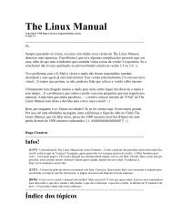
<strong>GRMON</strong> User’s <strong>Manual</strong>- 9 -2 Debugging concept2.1 OverviewThe <strong>GRMON</strong> debug monitor is intended to debug system-on-chip (SOC) designs based on the LEON processor.The monitor connects to a dedicated debug interface on the target hardware, through which it can performread and write cycles on the on-chip bus (AHB). The debug interface can be of various types: the LEON2 processorsupports debugging over a serial UART and 32-bit PCI, while LEON3 also supports JTAG, ethernet andspacewire (using the GRESB ethernet to spacewire bridge) debug interfaces. On the target system, all debuginterfaces are realized as AHB masters with the debug protocol implemented in hardware. There is thus nosoftware support necessary to debug a LEON system, and a target system does in fact not even need to have aprocessor present.Terminal GDB (port 2222)Command layerBasic commandsGDB protocol<strong>GRMON</strong>IP Debug driversGRLIB Debug DriversDebug interface driversUSBSerial I/FPCI JTAG EthernetGRESBDebug interfacesGRESBUSBdebug linkSerialdebug linkPCIdebug linkJTAGdebug linkEthernetdebug linkSpWRMAP linkLEON SOCTARGET SYSTEMAHBLEONProcessorMemoryControllerAPBBridgeCustomIP core<strong>GRMON</strong> can operate in two modes: command-line mode and GDB mode. In command-line mode, <strong>GRMON</strong>commands are entered manually through a terminal window. In GDB mode, <strong>GRMON</strong> acts as a GDB gatewayand translates the GDB extended-remote protocol to debug commands on the target system.<strong>GRMON</strong> is implemented using three functional layers: command layer, debug driver layer, and debug interfacelayer. The command layer consist of a general command parser which implements commands that are indepen-AEROFLEX GAISLER AB
- 12 -<strong>GRMON</strong> User’s <strong>Manual</strong>2.3 LEON2 target systemsThe plug&play information was introduced in the LEON3 processor (GRLIB), and is not available in LEON2.If <strong>GRMON</strong> is not able to detect the plug&play area, it will switch to a LEON2 legacy mode. LEON2 mode canalso be forced by starting <strong>GRMON</strong> with the -leon2 switch. A LEON2 system has a fixed set of IP cores andaddress mapping, and <strong>GRMON</strong> will use an internal plug&play table that describes this configuration:<strong>GRMON</strong> LEON debug monitor v1.1using port /dev/ttyUSB1 @ 115200 baudGRLIB plug&play not found, switching to LEON2 legacy modeinitialising .........detected frequency: 40 MHzComponentLEON2 Memory ControllerLEON2 SPARC V8 processorLEON2 Configuration registerLEON2 Timer UnitLEON2 UARTLEON2 UARTLEON2 Interrupt CtrlAHB Debug UARTLEON2 Debug Support UnitVendorEuropean Space AgencyEuropean Space AgencyEuropean Space AgencyEuropean Space AgencyEuropean Space AgencyEuropean Space AgencyEuropean Space AgencyGaisler ResearchGaisler ResearchUse command ’info sys’ to print a detailed report of attached coresgrmon[grlib]> inf sys00.04:00f European Space Agency LEON2 Memory Controller (ver 0)ahb: 00000000 - 20000000ahb: 20000000 - 40000000ahb: 40000000 - 80000000apb: 80000000 - 800000108-bit prom @ 0x0000000032-bit sdram: 1 * 64 Mbyte @ 0x40000000, col 9, cas 2, ref 15.6 us01.04:002 European Space Agency LEON2 SPARC V8 processor (ver 0)apb: 80000014 - 8000001802.04:008 European Space Agency LEON2 Configuration register (ver 0)apb: 80000024 - 80000028val: 6877bf0003.04:006 European Space Agency LEON2 Timer Unit (ver 0)apb: 80000040 - 8000007004.04:007 European Space Agency LEON2 UART (ver 0)apb: 80000070 - 80000080baud rate 3840005.04:007 European Space Agency LEON2 UART (ver 0)apb: 80000080 - 80000090baud rate 3840006.04:005 European Space Agency LEON2 Interrupt Ctrl (ver 0)apb: 80000090 - 800000a007.01:007 Gaisler Research AHB Debug UART (ver 0)apb: 800000c0 - 800000d0baud rate 115200, ahb frequency 40.0008.01:002 Gaisler Research LEON2 Debug Support Unit (ver 0)ahb: 90000000 - a0000000trace buffer 512 lines, stack pointer 0x43fffff0CPU#0 win 8, hwbp 2, V8 mul/div, lddel 1icache 1 * 8 kbyte, 32 byte/linedcache 1 * 8 kbyte, 32 byte/linegrmon[grlib]>AEROFLEX GAISLER AB
<strong>GRMON</strong> User’s <strong>Manual</strong>- 13 -The plug&play table used for LEON2 is fixed, and no automatic detection of present cores is attempted. Onlythose cores that need to be initialized by <strong>GRMON</strong> are included in the table, so the listing might not correspondto the actual target. It is however possible to load a custom configuration file that describes the target systemconfiguration using the -cfg startup option:./grmon -cfg leon2.cfg<strong>GRMON</strong> LEON debug monitor v1.1using port /dev/ttyS0 @ 115200 baudreading configuration from leon2.cfginitialising ......detected frequency: 40 MHzComponentAHB Debug UARTGeneric APB UARTLEON2 Interrupt CtrlLEON2 Timer UnitLEON2 Memory ControllerLEON2 Debug Support UnitVendorGaisler ResearchGaisler ResearchEuropean Space AgencyEuropean Space AgencyEuropean Space AgencyGaisler ResearchUse command ’info sys’ to print a detailed report of attached coresgrmon[grlib]> inf sys00.01:007 Gaisler Research AHB Debug UART (ver 0)apb: 800000c0 - 800000d0baud rate 115200, ahb frequency 40.0001.01:00c Gaisler Research Generic APB UART (ver 0)apb: 80000070 - 80000080baud rate 3840002.04:005 European Space Agency LEON2 Interrupt Ctrl (ver 0)apb: 80000090 - 800000a003.04:006 European Space Agency LEON2 Timer Unit (ver 0)apb: 80000040 - 8000007004.04:00f European Space Agency LEON2 Memory Controller (ver 0)ahb: 00000000 - 20000000ahb: 20000000 - 40000000ahb: 40000000 - 80000000apb: 80000000 - 800000108-bit prom @ 0x0000000032-bit sdram: 1 * 64 Mbyte @ 0x40000000, col 9, cas 2, ref 15.6 us05.01:002 Gaisler Research LEON2 Debug Support Unit (ver 0)ahb: 90000000 - a0000000trace buffer 512 lines, stack pointer 0x43fffff0CPU#0 win 1, lddel 1icache 4 * 1 kbyte, 4 byte/line lrudcache 4 * 1 kbyte, 4 byte/line lrugrmon[grlib]>The format of the plug&play configuration file is described in section appendix C. It can be used for bothLEON3 and LEON2 systems. An example configuration file is also supplied with the <strong>GRMON</strong>-PRO distributionin src/cfg/leon2.cfg .AEROFLEX GAISLER AB
- 14 -<strong>GRMON</strong> User’s <strong>Manual</strong>3 Operation3.1 GeneralA <strong>GRMON</strong> debug session typically consists of the following steps:• Attaching to the target system and examining the configuration• Uploading application program and executing using <strong>GRMON</strong> commands• Attaching to GDB and debugging through the GDB protocolThe following sections will describe how the various steps are performed.3.2 Starting <strong>GRMON</strong><strong>GRMON</strong> is started by giving the <strong>GRMON</strong> command in a terminal window. Without options, <strong>GRMON</strong> will tryto connect to the target using the serial debug link. UART1 of the host (ttyS0 or COM1) will be used, with adefault baud rate of 115200 baud. On windows hosts, <strong>GRMON</strong> can be started in a command window (command.com)or in a cygwin shell. Below is the syntax and the accepted command line options:grmon [options]Options:-abaud baudrate-altcable nr-altjtag-baud brateSet application baudrate for UART 1 & 2. By default, 38400 baud is used.Choose which Altera cable to connect to if multiple cables are connected. Connect without-altcable to see the cable numbers.Connect to the JTAG Debug Link using Altera USB Blaster or Byte Blaster.Use brate for the DSU serial link. By default, 115200 baud is used. Possible baud rates are9600, 19200, 38400, 57600, 115200, 230400, 460800. Rates above 115200 need specialuart hardware on both host and target.-c batch_file Run the commands in the batch file at start-up.-dsudelay val Delay the DSU polling val ms. Normally <strong>GRMON</strong> will poll the DSU as fast as possible.-edac-eth-freq sysclk-gdb-gresb-ioarea addr-jtag-jtagcfg fileEnable EDAC operation in memory controllers that support it.Connect using ethernet. Requires the EDCL core to be present in the target system.Overrides the detected system frequency. The frequency is specified in MHz.Listen for GDB connection directly at start-up.Connect through the GRESB bridge. The target needs SpW core with RMAP.Specify the location of the I/O area. (Default is 0xFFF00000)Connect to the JTAG Debug Link using Xilinx Parallel Cable III or IV.Read custom JTAG Configuration file.-jtagdevice nr Choose which JTAG device to debug.-leon2-log file-niForce LEON2 legacy mode.Log session to the specified file. If the file already exists the new session is appended.This should be used when requesting support.Attach to running program without target initialisation.AEROFLEX GAISLER AB
<strong>GRMON</strong> User’s <strong>Manual</strong>- 15 --nothreadsDisable thread support.-pci vid:did[:i]Connect to target using PCI. The board is identified by vendor id, device id andoptionally instance number.-port gdbport Set the port number for GDB communications. Default is 2222.-rtems ver Override autodetected RTEMS version for thread support. ver should be 46 or 48.-stack valSet val as stack pointer for applications, overriding the auto-detected value.-u Put UART 1 in FIFO debug mode if hardware supports it, else put it in loop-back mode.Debug mode will enable both reading and writing to the UART from the monitor console.Loop-back mode will only enable reading. See section 3.4.8 “Forwarding application consoleI/O” on page 21-uart device-ucmd file-usb-wildcard-xilusbBy default, <strong>GRMON</strong> communicates with the target using the first uart port of the host. Thiscan be overridden by specifying an alternative device. Device names depend on the hostoperating system.Load a user command module.Connect to target using USB (GRUSB IP core).Connect to a WildCard PC Card via CardBus (Windows only).Connect to the JTAG Debug Link using Xilinx Platform USB cable.In addition, the debug drivers can also accept command line options.3.3 <strong>GRMON</strong> command-line interface<strong>GRMON</strong> dynamically loads libreadline.so if available on your host system, and uses readline() to enter andedit monitor commands. Short forms of the commands are allowed, e.g c, co, or con, are all interpreted as cont.Tab completion is available for commands, text-symbols and filenames. If libreadline.so is not found, fgets()is used instead (no history, poor editing capabilities and no tab-completion). Below is a description of some ofthe more common commands that are available regardless of loaded debug drivers. For the full list of commands,see appendix A.1.batch file_namedisas [length]dump [file]echohelpexecute a batch file of <strong>GRMON</strong> commandsdisassemble memorydump target memory to file in srecord formatecho string in monitor windowshow available commands or usage for specific commandinfo [drivers | libs | reg | sys] show available debug drivers, system registers or system configurationloadlog mem[addr] [length]symbolsquitwmem load a file into target memory (elf32 or srecord).Open a logfile and output some system information to it then continue to logthe current session to it. This command or the -log start-up option should beused when requesting support. If the start-up option -log is given thenfile_name can be omitted.display memoryshow symbols or load symbols from fileexit <strong>GRMON</strong>write word to memoryAEROFLEX GAISLER AB
- 16 -<strong>GRMON</strong> User’s <strong>Manual</strong>Below is a list of some of commands provided by the LEON debug support unit (DSU) debug driver. Thesecommands are available when a LEON processor and associated debug support unit is present in the target system.See appendix A.2 for a full list of DSU commands.break print or add breakpointbwatch [delay] [break] add bus watchpointcontdcachedelete floatgdb [port]go [addr]hbreakicacheprofile [0 | 1]registerrun [addr]tmode [none|ahb|cpu|both]stack [val]step [n]washwatch [addr]3.4 Common debug operations3.4.1 Loading of files to target memorycontinue executionshow data cachedelete breakpoint(s)display FPU registersconnect to GDB debuggerstart execution without initializationprint breakpoints or add hardware breakpoint (if available)show instruction cacheenable/disable/show simple profilingshow/set integer registersreset and start execution at last entry point, or at addrenable instruction and AHB trace buffersshow/set the stack pointersingle step one or [n] timesclear all SRAM/SDRAM memoryprint or add data watchpointA LEON software application can be uploaded to the target system memory using the load command:grmon> load stanford_leonsection: .text at 0x40000000, size 54368 bytessection: .data at 0x4000d460, size 2064 bytessection: .jcr at 0x40024e68, size 4 bytestotal size: 56436 bytes (90.9 kbit/s)read 196 symbolsentry point: 0x40000000The supported file format is elf32-sparc and srecord. Each section is loaded to its link address. The programentry point of the file is use to set the %pc when the application is later started with run. It is also possible toverify that the file has been loaded correctly using the verify command:grmon> veri stanford_leonsection: .text at 0x40000000, size 54368 bytessection: .data at 0x4000d460, size 2064 bytessection: .jcr at 0x40024e68, size 4 bytestotal size: 56436 bytes (64.9 kbit/s)entry point: 0x40000000Any discrepancies will be reported in the <strong>GRMON</strong> console.AEROFLEX GAISLER AB
<strong>GRMON</strong> User’s <strong>Manual</strong>- 17 -3.4.2 Running applicationsTo run a program, first use the load command to download the application and the run to start it. The programshould have been compiled with either the BCC, RCC or sparc-linux tool-chain.grmon> lo stanford_leonsection: .text at 0x40000000, size 54368 bytessection: .data at 0x4000d460, size 2064 bytessection: .jcr at 0x40024e68, size 4 bytestotal size: 56436 bytes (90.8 kbit/s)read 196 symbolsentry point: 0x40000000grmon> runStartingPerm Towers Queens Intmm Mm Puzzle Quick Bubble Tree FFT34 67 33 117 1117 367 50 50 250 1133Nonfloating point composite is 144Floating point composite is 973Program exited normally.grmon>The output from the application normally appears on the LEON UARTs and thus not in the <strong>GRMON</strong> console.However, if <strong>GRMON</strong> is started with the -u switch, the UART output is looped back to its own receiver andprinted on the console by <strong>GRMON</strong>. The application must be reloaded before it can be executed again, in orderto restore the .data segment. If the application uses the LEON MMU (e.g. linux-2.6) or installs data exceptionhandlers (e.g. eCos), the <strong>GRMON</strong> should be started with -nb to avoid going into break mode on a page-fault ordata exception. Note that the -u option does not work for snapgear linux applications. Instead, a terminal emulatorshould be connected to UART 1 of the target system. When running a debugger on the target the "ta 0x01"instruction will be used to set a breakpoint. To prevent <strong>GRMON</strong> from interpreting it as it’s own breakpointsand stop use the -nswb switch.3.4.3 Inserting breakpoints and watchpointsInstruction breakpoints are inserted using the break or hbreak commands. The break command inserts a softwarebreakpoint (ta 1), while hbreak will insert a hardware breakpoint using one of the IU watchpoint registers.To debug code in read-only memories, only hardware breakpoints can be used. Note that it is possible todebug any RAM-based code using software breakpoints, even where traps are disabled such as in trap handlers.Data write watchpoints are inserted using the watch command. A watchpoint can only cover one word address,block watchpoints are not supported by <strong>GRMON</strong>.The bwatch command inserts bus watchpoints that will freeze the trace buffer when hit. The processor canoptionally be put in debug mode whan the bus watchpoint is hit. This is controlled using the tmode command:tmode ahbbre nIf n = 0, the processor will not be halted when the watchpoint is hit. A value > 0 will break the processor andset the AHB trace buffer delay counter to the same value.AEROFLEX GAISLER AB
- 18 -<strong>GRMON</strong> User’s <strong>Manual</strong>3.4.4 Displaying processor registersThe current register window of a LEON processor can be displayed using the reg command:grmon> regINS LOCALS OUTS GLOBALS0: 00000008 0000000C 00000008 000000001: 80000070 00000020 80000070 000000082: 0000000D 43FFFDF0 0000000D 43FFF6F83: FFFFFFFF 00000003 FFFFFFFF 4000D0104: 43FFF7B8 00000001 43FFF7B8 000000015: 4000D008 00000004 4000D008 000000006: 43FFF618 00000000 43FFF618 000000007: 00000001 00000010 00000001 4000633Cpsr: F20000E2 wim: 00000080 tbr: 40000060 y: 00000000pc: 40003e44 be 0x40003fb8npc: 40003e48 mov %i1, %i3Other register windows can be displayed using reg wn, when n denotes the window number. Use the floatcommand to show the FPU registers (if present).3.4.5 Displaying memory contentsAny memory location can be displayed using the mem (or x) command. The command requires an address andan optional length. If a length argument is provided, that is interpreted as the number of bytes to display. If aprogram has been loaded, text symbols can be used instead of a numeric address. The memory content is displayedhexa-decimal format, grouped in 32-bit words. The ASCII equivalent is printed at the end of the line.grmon> mem 0x4000000040000000 a0100000 29100004 81c52000 01000000 ...)....Å .....40000010 91d02000 01000000 01000000 01000000 . .............40000020 91d02000 01000000 01000000 01000000 . .............40000030 91d02000 01000000 01000000 01000000 . .............grmon> mem 0x40000000 1640000000 a0100000 29100004 81c52000 01000000 ...)....Å .....grmon> mem main 4840003278 9de3bf98 2f100085 31100037 90100000 .ã¿./...1..7....40003288 d02620c0 d025e178 11100033 40000b4b & À%áx...3@..K40003298 901223b0 11100033 40000af4 901223c0 ..#˚...3@..ô..#ÀIf the memory contents is SPARC machine code, the contents can be displayed in assembly code using thedisas command:grmon> dis 0x40000000 1040000000 a0100000 clr %l040000004 29100004 sethi %hi(0x40001000), %l440000008 81c52000 jmp %l44000000c 01000000 nop40000010 91d02000 ta 0x040000014 01000000 nopAEROFLEX GAISLER AB
<strong>GRMON</strong> User’s <strong>Manual</strong>- 19 -40000018 01000000 nop4000001c 01000000 nop40000020 91d02000 ta 0x040000024 01000000 nopgrmon> dis main40003278 9de3bf98 save %sp, -104, %sp4000327c 2f100085 sethi %hi(0x40021400), %l740003280 31100037 sethi %hi(0x4000dc00), %i040003284 90100000 clr %o040003288 d02620c0 st %o0, [%i0 + 0xc0]4000328c d025e178 st %o0, [%l7 + 0x178]40003290 11100033 sethi %hi(0x4000cc00), %o040003294 40000b4b call 0x40005fc040003298 901223b0 or %o0, 0x3b0, %o04000329c 11100033 sethi %hi(0x4000cc00), %o0400032a0 40000af4 call 0x40005e70400032a4 901223c0 or %o0, 0x3c0, %o03.4.6 Using the trace bufferThe LEON processor and associated debug support unit (DSU) can be configured with trace buffers to storeboth the latest executed instructions and the latest AHB bus transfers. The trace buffers are automaticallyenabled by <strong>GRMON</strong> during startup, but can also be individually enabled and disabled using tmode command.The commands ahb, inst and hist are used to display the contents of the buffers. Below is an example debugsession that shows the usage of breakpoints, watchpoints and the trace buffer:grmon> load samples/stanfordsection: .text at 0x40000000, size 41168 bytessection: .data at 0x4000a0d0, size 1904 bytestotal size: 43072 bytes (94.2 kbit/s)read 158 symbolsgrmon> tm bothcombined processor/AHB tracinggrmon> break Fftgrmon> watch 0x4000a500grmon> brenum address type1 : 0x40003608 (soft)2 : 0x4000a500 (watch)grmon> runwatchpoint 2 free + 0x1c8 (0x400042d0)grmon> ahhtime address type data trans size burst mst lock resp tt pil irl239371467 400042d8 read 38800002 3 2 1 0 0 0 06 0 0239371469 400042dc read d222a100 3 2 1 0 0 0 06 0 0239371472 4000a4fc read 00000000 2 2 0 0 0 0 06 0 0239371480 4000a4fc write 000005d0 2 2 0 0 0 0 06 0 0239371481 90000000 read 000055f9 2 2 0 3 0 0 06 0 0grmon> insttime address instruction result239371473 400042bc ld [%o2 + 0xfc], %o0 [00000000]239371475 400042c0 cmp %o1, %o0 [000005d0]239371476 400042c4 bgu,a 0x400042cc [00000000]239371478 400042c8 st %o1, [%o2 + 0xfc] [4000a4fc 000005d0]239371479 400042cc sethi %hi(0x4000a400), %o2 [4000a400]grmon> del 2grmon> breaknum address type1 : 0x40003608 (soft)AEROFLEX GAISLER AB
- 20 -<strong>GRMON</strong> User’s <strong>Manual</strong>grmon> contbreakpoint 1 Fft (0x40003608)grmon> hist254992755 40003870 sethi %hi(0x4001f800), %l0 [4001f800]254992759 ahb read, mst=0, size=2 [40003880 94146198]254992760 40003874 mov 19, %i0 [00000013]254992761 ahb read, mst=0, size=2 [40003884 961423cc]254992762 40003878 mov 256, %o0 [00000100]254992763 ahb read, mst=0, size=2 [40003888 190fec00]254992764 4000387c or %l2, 0x28c, %o1 [40014e8c]254992765 ahb read, mst=0, size=2 [4000388c 7fffff5f]254992766 40003880 or %l1, 0x198, %o2 [40014598]254992767 ahb read, mst=0, size=2 [40003890 9a102000]254992769 ahb read, mst=0, size=2 [40003894 b0863fff]254992771 40003884 or %l0, 0x3cc, %o3 [4001fbcc]254992772 40003888 sethi %hi(0x3fb00000), %o4 [3fb00000]254992773 4000388c call 0x40003608 [4000388c]254992774 40003890 mov 0, %o5 [00000000]When printing executed instructions, the value within brackets denotes the instruction result, or in the case ofstore instructions the store address and store data. The value in the first column displays the relative time, equalto the DSU timer. The time is taken when the instruction completes in the last pipeline stage (write-back) of theprocessor. In a mixed instruction/AHB display, AHB address and read or write value appear within brackets.The time indicates when the transfer completed, i.e. when HREADY was asserted. Note: when switchingbetween tracing modes the contents of the trace buffer will not be valid until execution has been resumed andthe buffer refilled.3.4.7 Profiling<strong>GRMON</strong> supports profiling of LEON applications when run on real hardware. The profiling function collects(statistical) information on the amount of execution time spend in each function. Due to its non-intrusivenature, the profiling data does not take into consideration if the current function is called from within anotherprocedure. Even so, it still provides useful information and can be used for application tuning.grmon> profile 1Profiling enabledgrmon> runresuming at 0x40000000StartingPerm Towers Queens Intmm Mm Puzzle Quick Bubble Tree FFT50 33 17 116 1100 217 33 34 266 934Nonfloating point composite is 126Floating point composite is 862Program exited normally.grmon> proffunction samples ratio(%)__unpack_f 23627 16.92__mulsf3 22673 16.24__pack_f 17051 12.21__divdi3 14162 10.14.umul 8912 6.38Fit 7594 5.44__muldi3 6453 4.62_window_overflow 3779 2.70AEROFLEX GAISLER AB
- 21 -<strong>GRMON</strong> User’s <strong>Manual</strong>Insert 3392 2.42__addsf3 3327 2.38_window_underflow 2734 1.95__subsf3 2409 1.72Fft 2207 1.58start 2165 1.55Innerproduct 2014 1.44Bubble 1767 1.26rInnerproduct 1443 1.03Place 1371 0.98Remove 1335 0.95Try 1275 0.91Permute 1125 0.80NOTE: profiling is not supported in systems based on the first-generation LEON2-FT processors, such asLEON2FT-UMC and AT697E.3.4.8 Forwarding application console I/OIf <strong>GRMON</strong> is started with -u, the LEON UART1 will be placed in FIFO debug mode if supported by the hardware.If not loop-back mode will be used instead. In both modes flow-control will be enabled.Debug mode was added in GRLIB 1.0.17-b2710, and will be reported by info sys in <strong>GRMON</strong> as DSU mode(FIFO debug).Both in loop-back mode and in FIFO debug mode the UART will be polled regularly during execution of anapplication and all console output will be printed on the <strong>GRMON</strong> console. It is then not necessary to connect aseparate terminal to UART1 to see the application output.With FIFO debug mode it will also be possible to enter text in <strong>GRMON</strong> which will be inserted into the UARTreceive FIFO. These insertions will trigger interrupts if receiver FIFO interrupts are enabled. This makes it possibleto use <strong>GRMON</strong> as a terminal when running an O/S such as Linux.The following restrictions must be met by the application to support either loop-back mode or FIFO debugmode:• The UART control register must not be modified such that neither loop-back nor FIFO debug mode isdisabled• In loop-back mode the UART data register must not be readThis means that -u cannot be used with PROM images created by MKPROM. Also loop-back mode can not beused in kernels using interrupt driven UART consoles (e.g. linux).Note: RXVT must be disabled for debug mode to work in a MSYS console on Windows. This can be done bydeleting or renaming the file rxvt.exe inside the bin directory, e.g., C:\msys\1.0\bin. Starting with MSYS-1.0.11 this will be the default.3.4.8.1 UART debug modeWhen the application is running with UART debug mode enabled the following key sequences will be available.Ctrl+A B - Toggle delete to backspace conversionCtrl+A C - Send break (Ctrl+C) to the running applicationCtrl+A D - Toggle backspace to delete conversionCtrl+A E - Toggle local echo on/offCtrl+A H - Show a help messageAEROFLEX GAISLER AB
- 22 -<strong>GRMON</strong> User’s <strong>Manual</strong>Ctrl+A N - Enable/disable newline insertion on carriage returnCtrl+A S - Show current settingsTheese can be used to adjust the input to what the target system expects.3.4.9 Attaching to a target system without initializationWhen <strong>GRMON</strong> connects to a target system, it probes the configuration and initializes memory and registers.To determine why a target has crashed, or resume debugging without reloading the application, it might bedesirable to connect to the target without performing a (destructive) initialization. This can be done by specifyingthe -ni switch during the start-up of <strong>GRMON</strong>. The system information print-out (info sys) will then howevernot be able to display the correct memory settings. The use of the -stack option is also necessary in casethe application is later restarted.3.4.10 Multi-processor supportIn systems with more than one LEON3 processors, the cpu command can be used to control the state anddebugging focus of the processors. In MP systems, the processors are enumerated with 0 - n-1, where n is thenumber of processors. Each processor can be in two states; enabled or disabled. When enabled, the processorwill be started when any of the run, cont or go commands are given. When disabled, the processor will remainhalted regardless of which command that are given. In addition, one of the enabled processor will also beactive. All debugging commands such as displaying registers or adding break points will be directed to theactive processor only. Switching of active processor can be done using the ‘cpu active n’ commandAt start-up, processor 0 is enabled and active while remaining processors are disabled. This allows non-MPsoftware to execute on MP systems. Additional processors can be enabled using the ‘cpu enable n’ command:grmon[grlib]> cpucpu 0: enabled activecpu 1: disabledgrmon[grlib]> cpu en 1cpu 0: enabled activecpu 1: enabledgrmon[grlib]> cpu act 1cpu 0: enabledcpu 1: enabled activeIf <strong>GRMON</strong> is started with the -mp switch, all processors will be enabled by default.Breakpoints are maintained on processor basis. When executing, only the breakpoints of the active processorare enabled, the breakpoints of the other processors are not enabled or inserted into the main memory.It is possible to debug MP systems using GDB. When GDB is attached, it is the currently active processor thatwill receive the GDB commands. Switching of processor can only be done by detaching GDB, selecting a differentprocessor to become active, and the re-attaching GDB. Note that GDB remembers the breakpointsbetween detach and re-attachment.3.4.11 Using EDAC protected memorySome versions of LEON2FT or LEON3FT might use EDAC protected memory. To enable the memory EDACduring execution, start <strong>GRMON</strong> with the -edac switch. Before any application is loaded, issue the wash commandto write all RAM memory locations and thereby initialize the EDAC checksums.$ grmon -ramws 1 -edacAEROFLEX GAISLER AB
- 23 -<strong>GRMON</strong> User’s <strong>Manual</strong>grlib> washclearing 191 kbyte SRAM: 40000000 - 4002fffcclearing 1024 kbyte SDRAM: 60000000 - 60100000grlib>By default wash writes to the whole memory area which has been detected or forced with a command lineswitch. A parameter can also be given which sets the amount of memory in bytes to be washed for SRAM(SDRAM always uses the detected size of the memory).$ grmon -ramws 1 -edacgrlib> wash 65536clearing 64 kbyte SRAM: 40000000 - 40010000clearing 1024 kbyte SDRAM: 60000000 - 60100000grlib>If the memory controller has support for EDAC with 8-bit wide SRAM memory, the upper part of the memorywill consist of checkbits. In this case the wash will only write to the data area (the checkbits will automaticallybe written by the memory controller). The amount of memory written will be displayed in <strong>GRMON</strong>.3.5 Symbolic debug information3.5.1 Symbol table<strong>GRMON</strong> will automatically extract the symbol information from elf-files. The symbols can be used where anaddress is expected:grmon> break maingrmon> runbreakpoint 1 main (0x40001ac8)grmon> disas strlen 340001e4c 808a2003 andcc %o0, 0x3, %g040001e50 12800016 bne 0x40001ea840001e54 96100008 mov %o0, %o3The symbols command can be used to display all symbols, or to read in symbols from an alternate (elf) file:grmon[dsu]> symbols samples/helloread 71 symbolsgrmon[dsu]> symbols0x40000000 L _trap_table0x40000000 L start0x4000102c L _window_overflow0x40001084 L _window_underflow0x400010dc L _fpdis0x400011a4 T _flush_windows0x400011a4 T _start0x40001218 L fstatReading symbols from alternate files is necessary when debugging self-extracting applications, such as bootpromscreated with mkprom or linux/uClinux.AEROFLEX GAISLER AB
- 24 -<strong>GRMON</strong> User’s <strong>Manual</strong>3.6 GDB interface3.6.1 Attaching to GDB<strong>GRMON</strong> can act as a remote target for GDB, allowing symbolic debugging of target applications. To initiateGDB communications, start the monitor with the -gdb switch or use the <strong>GRMON</strong> gdb command:$ grmon -gdbusing port /dev/ttyS0 @ 115200 baudgdb interface: using port 2222Then, start GDB in a different window and connect to <strong>GRMON</strong> using the extended-remote protocol. Bydefault, <strong>GRMON</strong> listens on port 2222 for the GDB connection:(gdb) target extended-remote pluto:2222Remote debugging using pluto:22220x40000800 in start ()(gdb)3.6.2 Running application in GDBTo load and start an application, use the GDB load and run command.$ gdb stanford(gdb) target extended-remote pluto:2222Remote debugging using pluto:22220x40000800 in start ()(gdb) loadLoading section .text, size 0xcb90 lma 0x40000000Loading section .data, size 0x770 lma 0x4000cb90Start address 0x40000000, load size 54016Transfer rate: 61732 bits/sec, 278 bytes/write.(gdb) bre mainBreakpoint 1 at 0x400039c4: file stanford.c, line 1033.(gdb) runThe program being debugged has been started already.Start it from the beginning? (y or n) yStarting program: /home/john/samples/stanfordBreakpoint 1, main () at stanford.c:10331033 fixed = 0.0;(gdb)To interrupt execution, Ctrl-C can be typed in both GDB and <strong>GRMON</strong> windows. The program can be restartedusing the GDB run command but the program image needs to be reloaded first using the load command. Softwaretrap 1 (ta 1) is used by GDB to insert breakpoints and should not be used by the application.AEROFLEX GAISLER AB
- 25 -<strong>GRMON</strong> User’s <strong>Manual</strong>3.6.3 Executing <strong>GRMON</strong> commands in GDBWhile GDB is attached to <strong>GRMON</strong>, normal <strong>GRMON</strong> commands can be executed using the GDB monitorcommand. Output from the <strong>GRMON</strong> commands is then displayed in the GDB console:(gdb) monitor histtime address instruction result4484188 40001e90 add %g2, %o2, %g3 [6e1f766e]4484194 40001e94 andn %g3, %g2, %g2 [001f0000]4484195 40001e98 andcc %g2, %o0, %g0 [00000000]4484196 40001e9c be,a 0x40001e8c [40001e3c]4484197 40001ea0 add %o1, 4, %o1 [40003818]4484198 40001e8c ld [%o1], %g2 [726c6421]4484200 40001e90 add %g2, %o2, %g3 [716b6320]4484201 40001e94 andn %g3, %g2, %g2 [01030300]4484202 40001e98 andcc %g2, %o0, %g0 [00000000]4484203 40001e9c be,a 0x40001e8c [40001e3c]3.6.4 DetachingIf GDB is detached using the detach command, the monitor returns to the command prompt, and the programcan be debugged using the standard <strong>GRMON</strong> commands. The monitor can also be re-attached to GDB by issuingthe gdb command to the monitor (and the target command to GDB).<strong>GRMON</strong> translates SPARC traps into (UNIX) signals which are properly communicated to GDB. If the applicationencounters a fatal trap, execution will be stopped exactly before the failing instruction. The target memoryand register values can then be examined in GDB to determine the error cause.3.6.5 Specific GDB optimisation<strong>GRMON</strong> detects GDB access to register window frames in memory which are not yet flushed and only residein the processor register file. When such a memory location is read, <strong>GRMON</strong> will read the correct value fromthe register file instead of the memory. This allows GDB to form a function trace-back without any (intrusive)modification of memory. This feature is disabled during debugging of code where traps are disabled, since novalid stack frame exist at that point.<strong>GRMON</strong> detects the insertion of GDB breakpoints, in form of the ‘ta 1’ instruction. When a breakpoint isinserted, the corresponding instruction cache tag is examined, and if the memory location was cached the tag iscleared to keep memory and cache synchronized.3.6.6 Limitations of GDB interfaceFor optimal operation, GDB 6.4 configured for <strong>GRMON</strong> should be used (provided with RCC and BCC compilers).Do not use the GDB where command in parts of an application where traps are disabled (e.g.trap handlers).Since the stack pointer is not valid at this point, GDB might go into an infinite loop trying to unwind false stackframes.AEROFLEX GAISLER AB
- 26 -<strong>GRMON</strong> User’s <strong>Manual</strong>3.7 Thread support<strong>GRMON</strong> has thread support for the RTEMS operating system. Additional OS support will be added to futureversions. The GDB interface of <strong>GRMON</strong> is also thread aware and the related GDB commands are describedlater.3.7.1 <strong>GRMON</strong> thread commandsthread info - lists all known threads. The currently running thread is marked with an asterisk.grlib> thread infoName | Type | Id | Prio | Ticks | Entry point | PC | State----------------------------------------------------------------------------------------------------------------------------------Int. | internal | 0x09010001 | 255 | 138 | _CPU_Thread_Idle_body | 0x4002f760 _Thread_Dispatch + 0x11c | READY----------------------------------------------------------------------------------------------------------------------------------UI1 | classic | 0x0a010001 | 120 | 290 | Init | 0x4002f760 _Thread_Dispatch + 0x11c | READY----------------------------------------------------------------------------------------------------------------------------------ntwk | classic | 0x0a010002 | 100 | 11 | rtems_bsdnet_schedneti | 0x4002f760 _Thread_Dispatch + 0x11c | READY----------------------------------------------------------------------------------------------------------------------------------DCrx | classic | 0x0a010003 | 100 | 2 | rtems_bsdnet_schedneti | 0x4002f760 _Thread_Dispatch + 0x11c | Wevnt----------------------------------------------------------------------------------------------------------------------------------DCtx | classic | 0x0a010004 | 100 | 4 | rtems_bsdnet_schedneti | 0x4002f760 _Thread_Dispatch + 0x11c | Wevnt----------------------------------------------------------------------------------------------------------------------------------FTPa | classic | 0x0a010005 | 10 | 1 | split_command | 0x4002f760 _Thread_Dispatch + 0x11c | Wevnt----------------------------------------------------------------------------------------------------------------------------------FTPD | classic | 0x0a010006 | 10 | 1 | split_command | 0x4002f760 _Thread_Dispatch + 0x11c | Wevnt----------------------------------------------------------------------------------------------------------------------------------* HTPD | classic | 0x0a010007 | 40 | 79 | rtems_initialize_webse | 0x40001b60 console_outbyte_polled + 0x34 | READY----------------------------------------------------------------------------------------------------------------------------------thread bt - do a backtrace of a thread.Backtrace of inactive thread:grlib> thread bt 0x0a010003%pc#0 0x4002f760 _Thread_Dispatch + 0x11c#1 0x40013ed8 rtems_event_receive + 0x88#2 0x40027824 rtems_bsdnet_event_receive + 0x18#3 0x4000b664 websFooter + 0x484#4 0x40027708 rtems_bsdnet_schednetisr + 0x158A backtrace of the current thread (equivalent to normal bt command):grlib> thread bt 0x0a010007%pc%sp#0 0x40001b60 0x43fea130 console_outbyte_polled + 0x34#1 0x400017fc 0x43fea130 console_write_support + 0x18#2 0x4002dde8 0x43fea198 rtems_termios_puts + 0x128#3 0x4002df60 0x43fea200 rtems_termios_puts + 0x2a0#4 0x4002dfe8 0x43fea270 rtems_termios_write + 0x70#5 0x400180a4 0x43fea2d8 rtems_io_write + 0x48#6 0x4004eb98 0x43fea340 device_write + 0x2c#7 0x40036ee4 0x43fea3c0 write + 0x90#8 0x4001118c 0x43fea428 trace + 0x38#9 0x4000518c 0x43fea498 websOpenListen + 0x108#10 0x40004fb4 0x43fea500 websOpenServer + 0xc0#11 0x40004b0c 0x43fea578 rtems_initialize_webserver + 0x204#12 0x40004978 0x43fea770 rtems_initialize_webserver + 0x70#13 0x40053380 0x43fea7d8 _Thread_Handler + 0x10c#14 0x40053268 0x43fea840 __res_mkquery + 0x2c8AEROFLEX GAISLER AB
- 27 -<strong>GRMON</strong> User’s <strong>Manual</strong>3.7.2 GDB thread commands<strong>GRMON</strong> needs the symbolic information of the image that is being debugged to be able to check for threadinformation. Therefor the symbols needs to be read from the image using the symbol command before issuingthe gdb command.When a program running in GDB stops <strong>GRMON</strong> reports which thread it is in. The command info threads canbe used in GDB to list all known threads.Program received signal SIGINT, Interrupt.[Switching to Thread 167837703]0x40001b5c in console_outbyte_polled (port=0, ch=113 ’q’) at ../../../../../../../../../rtems-4.6.5/c/src/lib/libbsp/sparc/leon3/console/debugputs.c:3838 while ( (LEON3_Console_Uart[LEON3_Cpu_Index+port]->status & LEON_REG_UART_STATUS_THE) == 0 );(gdb) info threads8 Thread 167837702 (FTPD Wevnt) 0x4002f760 in _Thread_Dispatch () at ../../../../../../rtems-4.6.5/cpukit/score/src/threaddispatch.c:1097 Thread 167837701 (FTPa Wevnt) 0x4002f760 in _Thread_Dispatch () at ../../../../../../rtems-4.6.5/cpukit/score/src/threaddispatch.c:1096 Thread 167837700 (DCtx Wevnt) 0x4002f760 in _Thread_Dispatch () at ../../../../../../rtems-4.6.5/cpukit/score/src/threaddispatch.c:1095 Thread 167837699 (DCrx Wevnt) 0x4002f760 in _Thread_Dispatch () at ../../../../../../rtems-4.6.5/cpukit/score/src/threaddispatch.c:1094 Thread 167837698 (ntwk ready) 0x4002f760 in _Thread_Dispatch () at ../../../../../../rtems-4.6.5/cpukit/score/src/threaddispatch.c:1093 Thread 167837697 (UI1 ready) 0x4002f760 in _Thread_Dispatch () at ../../../../../../rtems-4.6.5/cpukit/score/src/threaddispatch.c:1092 Thread 151060481 (Int. ready) 0x4002f760 in _Thread_Dispatch () at ../../../../../../rtems-4.6.5/cpukit/score/src/threaddispatch.c:109* 1 Thread 167837703 (HTPD ready ) 0x40001b5c in console_outbyte_polled (port=0, ch=113 ’q’)at ../../../../../../../../../rtems-4.6.5/c/src/lib/libbsp/sparc/leon3/console/debugputs.c:38Using the thread command a specified thread can be selected:(gdb) thread 8[Switching to thread 8 (Thread 167837702)]#0 0x4002f760 in _Thread_Dispatch () at ../../../../../../rtems-4.6.5/cpukit/score/src/threaddispatch.c:109109 _Context_Switch( &executing->Registers, &heir->Registers );Then a backtrace of the selected thread can be printed using the bt command:(gdb) bt#0 0x4002f760 in _Thread_Dispatch () at ../../../../../../rtems-4.6.5/cpukit/score/src/threaddispatch.c:109#1 0x40013ee0 in rtems_event_receive (event_in=33554432, option_set=0, ticks=0, event_out=0x43fecc14)at ../../../../leon3/lib/include/rtems/score/thread.inl:205#2 0x4002782c in rtems_bsdnet_event_receive (event_in=33554432, option_set=2, ticks=0, event_out=0x43fecc14)at ../../../../../../rtems-4.6.5/cpukit/libnetworking/rtems/rtems_glue.c:641#3 0x40027548 in soconnsleep (so=0x43f0cd70) at ../../../../../../rtems-4.6.5/cpukit/libnetworking/rtems/rtems_glue.c:465#4 0x40029118 in accept (s=3, name=0x43feccf0, namelen=0x43feccec) at ../../../../../../rtems-4.6.5/cpukit/libnetworking/rtems/rtems_syscall.c:215#5 0x40004028 in daemon () at ../../../../../../rtems-4.6.5/c/src/libnetworking/rtems_servers/ftpd.c:1925#6 0x40053388 in _Thread_Handler () at ../../../../../../rtems-4.6.5/cpukit/score/src/threadhandler.c:123#7 0x40053270 in __res_mkquery (op=0, dname=0x0, class=0, type=0, data=0x0, datalen=0, newrr_in=0x0, buf=0x0,buflen=0)at ../../../../../../../rtems-4.6.5/cpukit/libnetworking/libc/res_mkquery.c:199#8 0x00000008 in ?? ()#9 0x00000008 in ?? ()Previous frame identical to this frame (corrupt stack?)AEROFLEX GAISLER AB
- 28 -<strong>GRMON</strong> User’s <strong>Manual</strong>It is possible to use the frame command to select a stack frame of interest and examine the registers using theinfo registers command. Note that the info registers command only can see the following registers for aninactive task: g0-g7, l0-l7, i0-i7, o0-o7, pc and psr. The other registers will be displayed as 0:(gdb) frame 5#5 0x40004028 in daemon () at ../../../../../../rtems-4.6.5/c/src/libnetworking/rtems_servers/ftpd.c:19251925 ss = accept(s, (struct sockaddr *)&addr, &addrLen);(gdb) info regg0 0x0 0g1 0x0 0g2 0xffffffff -1g3 0x0 0g4 0x0 0g5 0x0 0g6 0x0 0g7 0x0 0o0 0x3 3o1 0x43feccf0 1140772080o2 0x43feccec 1140772076o3 0x0 0o4 0xf34000e4 -213909276o5 0x4007cc00 1074252800sp 0x43fecc88 0x43fecc88o7 0x40004020 1073758240l0 0x4007ce88 1074253448l1 0x4007ce88 1074253448l2 0x400048fc 1073760508l3 0x43feccf0 1140772080l4 0x3 3l5 0x1 1l6 0x0 0l7 0x0 0i0 0x0 0i1 0x40003f94 1073758100i2 0x0 0i3 0x43ffafc8 1140830152i4 0x0 0i5 0x4007cd40 1074253120fp 0x43fecd08 0x43fecd08i7 0x40053380 1074082688y 0x0 0psr 0xf34000e0 -213909280wim 0x0 0tbr 0x0 0pc 0x40004028 0x40004028 npc 0x4000402c 0x4000402c fsr 0x0 0csr 0x0 0It is not supported to set thread specific breakpoints. All breakpoints are global and stops the execution of allthreads. It is not possible to change the value of registers other than those of the current thread.AEROFLEX GAISLER AB
<strong>GRMON</strong> User’s <strong>Manual</strong>- 29 -4 Debug interfaces4.1 OverviewThe default communications interface between <strong>GRMON</strong> and the target system is the host’s serial port connectedto the AHB uart of the target system. Connecting using USB, JTAG, PCI or ethernet can be performedusing the switches listed below:-ethConnect using ethernet. Requires the EDCL core to be present in the target system.-pci vid:did[:i]Connect through PCI. Board is identified by vendor id, device id and optionanlly instancenumber. Requires a supported PCI core.-jtag-altjtag-gresb-xilusb-usb-wildcard4.2 Serial debug interfaceConnect to the JTAG Debug Link using Xilinx Parallel Cable III or IV.Connect to the JTAG Debug Link using Altera download cable (USB or parallel).Connect through the GRESB bridge. The target needs a SpW core with RMAP.Connect to the JTAG Debug Link using Xilinx Platform USB cable.Connect to the USB debug link. Requires the USBDCL core to be present in the target.Connect to WildCard PC Card. Requires the WILD2AHB core to be present in target.To successfully attach <strong>GRMON</strong> using the AHB uart, first connect the serial cable between the uart connectorson target board and the host system. Then power-up and reset the target board and start <strong>GRMON</strong>. Use the-uart option in case the target is not connected to the first uart port of your host. Below is a list of start-upswitches applicable for the AHB uart interface:-baud baudrateUse baudrate for the DSU serial link. By default, 115200 baud is used. Possible baud ratesare 9600, 19200, 38400, 57600, 115200, 230400, 460800. Rates above 115200 need specialuart hardware on both host and target.-ibaud baudrateUse baudrate to determine the target processor frequency. Lower rate means higher accuracy.The detected frequency is printed on the console during startup. By default, 115200baud is used.-uart deviceBy default, <strong>GRMON</strong> communicates with the target using the first uart port of the host. Thiscan be overridden by specifying an alternative device. Device names depend on the hostoperating system. On unix systems (and cygwin), serial devices are named as /dev/ttyXX.On windows, use com1 - 4.When <strong>GRMON</strong> connects to the target with the serial interface, the system clock frequency is calculated bycomparing the setting in the AHB uart baud rate generator to the used communications baud rate. This detectionhas limited accuracy, but can be improved by selecting a lower detection baud rate using the -ibaudswitch. On some hosts, it might be necessary to lower the baud rate in order to achieve a stable connection tothe target. In this case, use the -baud switch with the 57600 or 38400 options.AEROFLEX GAISLER AB
- 30 -<strong>GRMON</strong> User’s <strong>Manual</strong>4.3 Ethernet debug interfaceIf the target system uses the EDCL ethernet communication link core, <strong>GRMON</strong> can connect to the systemusing ethernet. In this case, start <strong>GRMON</strong> with -eth. The default network parameters can be set through additionalswitches:-emem Use size for the target system’s EDCL packet buffer. Default is 2 (kbytes)-ip Use ipnum for the target system IP number. Default is 192.168.0.51.-udp Use port for the target systemUDP port. Default is 8000.The IP address of the EDCL is determined at synthesis time, but can be changed using the edcl command:grlib> edcledcl ip 192.168.0.51, buffer 2 kbytegrlib> edcl 192.168.0.56edcl ip 192.168.0.56, buffer 2 kbyteNote that if the target is reset using the reset signal (or power-cycled), the default IP address is restored. Theedcl command can be given when <strong>GRMON</strong> is attached to the target with any interface (serial, JTAG, PCI ...),allowing to change the IP address to a value compatible with the network type, and then attach <strong>GRMON</strong> usingthe EDCL with the new IP number. If the edcl command is issued through the EDCL interface, <strong>GRMON</strong> mustbe re-started using the new IP address of the EDCL interface. The current IP number is also visible in ‘info sys’:grlib> info sys..03.01:01d Gaisler Research GR Ethernet MAC (ver 0)ahb master 3apb: 80000b00 - 80000c00edcl ip 192.168.0.52, buffer 2 kbyte4.4 JTAG debug interface4.4.1 Xilinx Parallel Cable III or IVIf target system has the JTAG AHB debug interface, <strong>GRMON</strong> can connect to the system through Xilinx ParallelCable III or IV. The cable should be connected to the host computers parallel port, and <strong>GRMON</strong> should bestarted with the -jtag switch. On linux systems, the <strong>GRMON</strong> binary has to be owned by the superuser (root)and have ‘s’ (set user or group ID on execution) permission bit set (chmod +s grmon). <strong>GRMON</strong> will report thedevices in the JTAG chain. If an unknown device is found, initialization of the JTAG chain will fail and<strong>GRMON</strong> will report the JTAG ID of the unknown device. In this case, use JTAG configuration file to describethe unknown device (see appendix D). If you report the device ID and corresponding JTAG instruction registerlength to Aeroflex Gaisler and the device will be supported in a future release of <strong>GRMON</strong>. Following switchcan be used with the JTAG debug interface:-pport Use parallel port 1 or 2 (default is 1).$ grmon -jtag -uusing JTAG cable on parallel portJTAG chain: xc3s1500 xcf04s xcf04sAEROFLEX GAISLER AB
<strong>GRMON</strong> User’s <strong>Manual</strong>- 31 -4.4.2 Altera USB Blaster or Byte BlasterFor GRLIB systems implemented on Altera devices <strong>GRMON</strong> can use USB blaster or Byte Blaster cable toconnect to the system. <strong>GRMON</strong> is started with -altjtag switch. <strong>GRMON</strong> will automatically detect cable connectedto the host computer. On Linux systems, the path to Quartus shared libraries has to be defined in theLD_LIBRARY_PATH environment variable, e.g.:$ export LD_LIBRARY_PATH=$LD_LIBRARY_PATH:/usr/local/quartus/linux$ grmon -altjtag<strong>GRMON</strong> LEON debug monitor v1.1.16cNote that the automatic frequency detection over USB is not always working due to unpredictable communicationlatencies. It is recommneded to use the -freq xx option to define the target frequency when using the AlteraUSB cable.4.4.3 Xilinx Platform USB Cable (Linux and Windows)JTAG debugging using the Xilinx USB Platform cable is supported on Linux and Windows systems. The platformcable models DLC9G and DLC10 are supported. The legacy model DLC9 is not supported. <strong>GRMON</strong>should be started with -xilusb switch, e.g.:$ grmon -xilusb -u<strong>GRMON</strong> LEON debug monitor v1.1.35Xilinx cable: Cable type/rev : 0x3JTAG chain: xc2v6000 xc18v04 xc18v04 xc18v04 xc18v04 xc18v04 xc18v04GRLIB build version: 2384initialising .............On Linux systems, the Xilinx USB drivers must be installed by executing ’./setup_pcusb’ in the ISE bin/lindirectory (see ISE documentation). Also, the program fxload must be available in /sbin on the used host.On Windows hosts, the USB cable drivers should be installed from ISE or ISE-Webpack. Xilinx ISE 10.1i-SP3or later is required. Then, the filter driver from the libusb project (http://libusb-win32.sourceforge.net, version0.1.12.1 or later is recommended) should be installed.Certain FPGA boards have a USB platform cable logic implemented directly on the board, using a CypressUSB device and a dedicated Xilinx CPLD. <strong>GRMON</strong> can also connect to these boards, using the -xilusb switch.Tested boards are Digilent XUP and XC3S1600E Development boards. Feed-back on other boards is welcome.If multiple Xilinx Platform USB Cables are connected the -xilport switch can be added to select one,where is an index starting from 0. By adding -xillist you can get a list of connected USB devices andthe -xilport combination to use.4.4.4 Choosing JTAG deviceIf the JTAG device chain contains more than one FPGA <strong>GRMON</strong> will not know which device to debug. Tochoose device manually use the option -jtagdevice X where X is the device number to connect to.AEROFLEX GAISLER AB
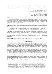
- 32 -<strong>GRMON</strong> User’s <strong>Manual</strong>4.5 Direct USB debug interface (Linux and Windows)<strong>GRMON</strong> can connect to targets equipped with the USBDCL core using the USB bus. To do so start <strong>GRMON</strong>with the -usb switch. Both USB 1.1 and 2.0 are supported. Several target systems can be connected to a singlehost at the same time. <strong>GRMON</strong> scans all the USB busses and claims the first free USBDCL interface. If thefirst target system encountered is already connected to another <strong>GRMON</strong> instance, the interface cannot beclaimed and the bus scan continues.On Linux the <strong>GRMON</strong> binary has to be owned by the superuser (root) and have ‘s’ (set user or group ID onexecution) permission bit set (chmod +s grmon).On Windows a driver has to be installed. The first the time the device is plugged in it should be automaticallydetected as seen in figure below.Then the new device can be found in the Device Manager. Press the right mouse button over the unknowndevice and choose update driver in the menu.AEROFLEX GAISLER AB
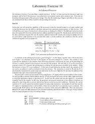
<strong>GRMON</strong> User’s <strong>Manual</strong>- 33 -Select "No, not this time" in the next window and click next.Select "Install from a list or specific location".In the last step choose to search for the best driver and include the path "<strong>GRMON</strong>_ROOT\libusb\bin" where<strong>GRMON</strong>_ROOT is the root directory of the <strong>GRMON</strong> installation, usually ’C:\opt\grmon-eval’ or’C:\opt\grmon-pro’. Then click next and Windows should detect the driver. Click on "finish" when its done andthen it should be possible to connect with <strong>GRMON</strong> using the -usb switch.AEROFLEX GAISLER AB
- 34 -<strong>GRMON</strong> User’s <strong>Manual</strong>4.6 PCI debug interfaceIf target system has a PCI interface, <strong>GRMON</strong> can connect to the system using the PCI bus. Start <strong>GRMON</strong> withthe -pci vendor_id:device_id[:instance] option and specify vendor id and device id in hexadecimal (with orwithout ‘0x’ prefix):.$ grmon -pci 16e3:1e0fThe default is to use the first instance of the board. If there are more than one board with the same vendor anddevice id the different boards can be selected with the instance number:$ grmon -pci 16e3:1e0f:2<strong>GRMON</strong> supports the Aeroflex Gaisler PCI cores inside GRLIB (pci_gr, pci_target, pci_mtf, pcidma) and theInsilicon PCI core (pci_is) on the AT697 (LEON2-FT) device.On Linux <strong>GRMON</strong> needs root privelege to be able to access PCI memory and I/O ports. This can be accomplishedby letting the <strong>GRMON</strong> binary be owned by root (chown root grmon) and setting the ’s’ (set user orgroup ID on execution) permission bit (chmod +s grmon).On Windows a special PCI driver must installed. It is available as an installer ’GRPCISetup.exe’ in the folder’pci’. It is a standard Windows installer which will install everthing that is needed for PCI to work with<strong>GRMON</strong>.4.7 GRESB debug interfaceTargets equipped with a Spacewire core with RMAP support can be debugged through the GRESB debuginterface using the GRESB Ethernet to Spacewire bridge. To do so start <strong>GRMON</strong> with the -gresb switch anduse the following switches to set the needed parameters:-ip Connect to the bridge using the IP address ipnum . Default is 192.168.0.51.-link Use link linknum on the bridge. Defaults to 0.AEROFLEX GAISLER AB
<strong>GRMON</strong> User’s <strong>Manual</strong>- 35 --dna The destination node address of the target. Defaults to 0xFE.-sna The SpW node address for the link used on the bridge. Defaults to 32.-dkey The destination key used by the targets RMAP interface. Defaults to 0.-clkdiv Divide the tx bit rate by div. If not specified, the current setting is used.-gresbtimeout Timeout period in seconds for RMAP replies. Defaults is 8.-gresbretry Number of retries for each timeout. Defaults to 0.-grusbUse USB rather then ethernet. The -gresb option must be omittedExamples: grmon -gresb -ip 192.168.0.55 -dna 0xfe -sna 32 -link 0 -clkdiv 1 -ugrmon -grusb -dna 0xfe -sna 32 -link 0 -clkdiv 1 -uNOTE: When using the -grusb switch the GRESB can not be used for normal operation. Only debuggingthrough <strong>GRMON</strong>.For further information about the GRESB bridge see the GRESB manual.4.8 WildCard debug interfaceThe WildCard is a development board from Annapolis Micro Systems, Inc. It contains a 32-bit CardBusinterface, programmable clock generator, a Processing Element (Virtex XCV300E -6 FPGA), two SSRAMmemory ports and two I/O ports.The necessary Windows drivers and API are delivered with the card. The wcapi.dll file should be in the searchpath. For more information, visit http://www.annapmicro.comFor <strong>GRMON</strong> to communicate with the WildCard, the GRLIB WILD2AHB - WildCard Debug Interface IPcore must be present in the Processing Element FPGA design. The WildCard debug interface supports only 32-bit AMBA accesses. <strong>GRMON</strong> and the WILD2AHB IP core have been tested on Windows XP with the followingWildCard software and hardware versions:• API version 1.8• Driver version 1.8• Firmware version 2.4• Hardware version 4.0, Rev. D:• XCV300E-BG352-6• 2 x 256kByte SSRAM, 10 nsBelow is a list of start-up switches applicable to the WildCard debug interface:-wildmhz mhz-wildfile fileSet the frequency of the F_CLK clock from the clock generator on the Wild-Card. The default is 20 MHz (see WildCard documentation for minimum andmaximum values).Set the name of the WildCard programming file. The default is “wildcardxcv300e.bin”,as generated by GRLIB.-wilddev device Set the WildCard device number. The default is 0.-wildstatEnable WildCard version and hardware information printout.AEROFLEX GAISLER AB
- 36 -<strong>GRMON</strong> User’s <strong>Manual</strong>5 Debug drivers5.1 LEON2 and LEON3 debug support unit (DSU) driversThe DSU debug drivers for LEON2 and LEON3 processors handle most of the functions regarding applicationdebugging, processor register access and trace buffer handling. Since the DSU for LEON2 and LEON3 are notidentical, two separate drivers are used.5.1.1 Internal commandsThe driver for the LEON2/3 debug support unit provides the following internal commands:ahb [length]Print the AHB trace buffer. The length AHB transfers will be printed,default is 10.break print or add breakpointbwatch [delay] [break]Add a buswatch at address addr with an optional delay.contcontinue executioncpu [enable | disable | active] cpuidControl processors in LEON3 multi-processor (MP) systems.Without parameters, the cpu command prints the processor status.dcache[0 | 1]show, enable or disable data cachedelete delete breakpoint(s)floatdisplay FPU registersgdb [port]connect to GDB debuggergo [addr]start execution without initializationhbreakprint breakpoints or add hardware breakpoint (if available)hist [length]Print the trace buffer. The length last executed instructions orAHB transfers will be printed, default is 10.icache [0 | 1]show, enable or disable instruction cachemmuprint the SRMMU registers (see also the -srmmu switch)mmu [mctrl|ctxp|ctx] val write value to mmu registerprofile [0 | 1]enable/disable/show simple profilingregistershow/set integer registersrun [addr]reset and start execution at last entry point, or at addrstack [val]show/set the stack pointerstep [n]single step one or [n] timesthread infoshow thread information (RTEMS only)tmode [proc | ahb | both | none]Select tracing mode between none, processor-only, AHB only or both.walk [address] do address translation for a virtual addresswashClear all SRAM and SDRAM memorywatch [addr]print or add data watchpointAEROFLEX GAISLER AB
<strong>GRMON</strong> User’s <strong>Manual</strong>- 37 -5.1.2 Command line switchesThe following command line switches are accepted:-mpStart-up in MP mode (all processors enabled)-srmmu Specifies that cpu has a SRMMU present. This will enable the SRMMUcommands as well as virtual address translation if SRMMU is enabled.5.2 Memory controller driverThe memory controller debug driver provides functions for memory probing and waitstate control. Theseswitched are applicable to the LEON2 memory controller (MCTRL), and the FTMCTRL, SRCTRL andFTSRCTRL memory controller cores.5.2.1 Internal commandsmcfg1 [value] Set the default value for memory configuration register 1. When the ‘run’ or ’load’ commandis given, MCFG1, 2&3 are initialized with their default values to provide the applicationwith a clean startup environment. If no value is give, the current default value isprinted.mcfg2 [value] As mcfg1 above, but setting the default value of the MCFG2 register.mcfg3 [value] As mcfg1 above, but setting the default value of the MCFG3 register.5.2.2 Command line switchesThe following start-up switches are recognized:-banks ram_banksOverrides the auto-probed number of populated ram banks.-cas delay Programs SDRAM to either 2 or 3 cycles CAS delay. Default is 2.-mcfg1, -mcfg2, -mcfg3Set the default value for memory configuration register 1, 2 or 3 respectively.-noflash-nosram-ram ram_size-romrws waitstates-romwws waitstates-romws waitstates-ramrws waitstates-ramwws waitstates-ramws waitstatesDo not probe for flash memory at start-upDisable sram and map sdram from address 0x40000000Overrides the auto-probed amount of static ram. Size is given in Kbytes.Set waitstates number of waitstates for rom reads.Set waitstates number of waitstates for rom writes.Set waitstates number of waitstates for both rom reads and writes.Set waitstates number of waitstates for ram reads.Set waitstates number of waitstates for ram writes.Set waitstates number of waitstates for both ram reads and writes.-trp3 Programs the SDRAM trp timing to 3 (sets bit 30 in mcfg2). Default is 2.-trfc valPrograms the SDRAM trcf field in mcfg2 to represent val ns.AEROFLEX GAISLER AB
- 38 -<strong>GRMON</strong> User’s <strong>Manual</strong>5.3 On-chip logic analyser driver (LOGAN)The LOGAN debug driver contains commands to control the LOGAN on-chip logic analyzer core. It allows toset various triggering conditions, and to generate VCD waveform files from trace buffer data. All logic analyzercommands are prefixed with la.5.3.1 Internal commandsla statusla armla resetReports status of logan (equivalent with writing just la).Arms the logan. Begins the operation of the analyzer and sampling starts.Stop the operation of the logan. Logic Analyzer returns to idle state.la pm [trig level] [pattern] [mask]la pat [trig level] [bit] [0 | 1]Sets/displays the complete pattern and mask of the specified trig level. If not fully specifiedthe input is zero-padded from the left. Decimal notation only possible for widths less thanor equal to 64 bits.Sets/displays the specified bit in the pattern of the specified trig level to 0/1.la mask [trig level] [bit] [0 | 1]Sets/displays the specified bit in the mask of the specified trig level to 0/1.la trigctrl [trig level] [match counter] [trig condition]Sets/displays the match counter and the trigger condition (1 = trig on equal, 0 = trig on notequal) for the specified trig level.la count [value]Set/displays the trigger counter. The value should be between zero and depth-1 and specifieshow many samples that should be taken after the triggering event.la div [value] Sets/displays the sample frequency divider register. If you specify e.g. “la div 5” the logicanalyzer will only sample a value every 5th clock cycle.la qual [bit] [value]Sets/displays which bit in the sampled pattern that will be used as qualifier and whatvalue it shall have for a sample to be stored.la dump [filename]This dumps the trace buffer in VCD format to the file specified (default is log.vcd).la view [start index] [stop index] [filename]Prints the specified range of the trace buffer in list format. If no filename is specified thecommands prints to the screen.la page [page] Sets/prints the page register of the logan. Normally the user doesn’t have to be concernedwith this because dump and view sets the page automatically. Only useful if accessing thetrace buffer manually via the <strong>GRMON</strong> mem command.The LOGAN driver can create a VCD waveform file using the ‘la dump’ command. The file setup.logan isused to define which part of the trace buffer belong to which signal. The file is read by the debug driver beforea VCD file is generated. An entry in the file consists of a signal name followed by its size in bits separated bywhite-space. Rows not having these two entries as well as rows beginning with an # are ignored.AEROFLEX GAISLER AB
- 39 -<strong>GRMON</strong> User’s <strong>Manual</strong>Example:count31_16 16count15_6 10count5_0 6This configuration has a total of 32 traced signals and they will be displayed as three different signals being 16,10 and 6 bits wide. The first signal in the configuration file maps to the most significant bits of the vector withthe traced signals. The created VCD file can be opened by waveform viewers such as GTKWave or Dinotrace.Below is an example trace displayed in GTKWave.To simplify the operation of the logic analyzer, a graphical GUI is available. The GUI is written in Tcl/Tk andcan be connected to <strong>GRMON</strong> using the GDB interface. To use the GUI, enter the gdb command in <strong>GRMON</strong>and then launch the tcl file logan.tcl.The left side of the GUI window has the settings for the different trig levels, i.e. pattern, mask, match counterand trigger condition. Which trig level the settings apply to is chosen from an option menu. The “Downloadconf” button transfers the values to the on-chip logic analyzer. The pattern and mask is padded with zeroesfrom the left if not fully specified. They can be entered either in hexadecimal or decimal but there is a limitationthat no signal can be wider than 64 bits.The right side of the window shows the status the settings which control the trace buffer. These settings are sentto the logic analyzer when the user presses enter. The ‘armed’ and ‘triggered’ fields of the status can be re-readby pressing the “Update status” button.There are also buttons to arm and reset the logic analyzer as well as to dump the vcd-file and launch GTK-Wave. Any <strong>GRMON</strong> command can be issued from the entry below these buttons.From the file menu the current configuration can be saved and a new one can be loaded. The GUI defaults tothe same configuration file as the <strong>GRMON</strong> debug driver. If the configuration is saved it adds information aboutthe setup which is ignored by <strong>GRMON</strong>. When saving/loading any filename may be specified but during startupthe GUI reads the “setup.logan” file. Only files previously saved by the GUI can be loaded from this menuoption.AEROFLEX GAISLER AB
- 40 -<strong>GRMON</strong> User’s <strong>Manual</strong>5.4 AMBA wrapper for Xilinx System MonitorThe debug driver driver for the AMBA wrapper for Xilinx System Monitor allows reading of device temperatureand voltages. The debug driver does not perform any calibration of the System Monitor.5.4.1 Internal commandsgrsysmon calibrategrsysmon temperaturegrsysmon voltageInitialize and calibrate out any offset and gain errorsDisplays temperature readingsDisplays voltage readings5.5 ATA/IDE controllerThe ATA/IDE controller is used when the target system contains the ATACTRL core. The driver implementsone command, ata, which displays the types of disk drives that are attached the IDE controller. Attached disksare not automatically probed when <strong>GRMON</strong> is started, but probing can be forced by starting <strong>GRMON</strong> with -ata. The command ‘info sys’ will then display the attached disks.AEROFLEX GAISLER AB
- 41 -<strong>GRMON</strong> User’s <strong>Manual</strong>5.6 DDR memory controller (DDRSPA)The driver for the DDRSPA memory controller performs the DDR initialization sequence, and probes theamount of available memory. To skip the probing and use the pre-configured values, add -nosdinit at start up.The ’info sys’ command will show the DDR timing and the amount of detected memory:04.01:025 Gaisler Research DDR266 Controller (ver 0)ahb: 40000000 - 50000000ahb: fff00100 - fff0020016-bit DDR : 1 * 64 Mbyte @ 0x40000000100 MHz, col 10, ref 7.8 us5.6.1 Command line switchesThe following start-up switches are recognized:-trp3 Programs the SDRAM trp timing to 3 (sets bit 30 in ddrcfg1). Default is 2.-trcd val Programs the SDRAM trcd timing to val - 2 (sets bit 26 in ddrcfg1). Default is 2.-trfc val-nisdinitPrograms the SDRAM trcf field in ddrcfg1 to represent val ns.To skip memory probing and use pre-configured values.5.7 DDR2 memory controller (DDR2SPA)The the driver for the DDR2SPA memory controller performs the DDR2 initialization sequence, and probesthe amount of available memory. To skip the probing and use the pre-configured values, add -nosdinit at startup. The ’info sys’ command will show the DDR2 timing and the amount of detected memory:00.01:02e Gaisler Research DDR2 Controller (ver 0x0)ahb: 40000000 - 60000000ahb: fff00100 - fff0020064-bit DDR2 : 1 * 256 Mbyte @ 0x40000000200 MHz, col 10, ref 7.8 us5.7.1 Internal commandsddr2cfg1 [value] Set the default value for DDR2 control register 1.ddr2cfg2 Print the value of DDR2 control register 2.ddr2cfg3 [value] Set the default value for DDR2 control register 3.ddr2delay [inc | dec | reset | value] Change read data input delay. Use inc to increment the delay with onetap-delay for all data bytes. Use dec to decrement all delays. Resetwill set the delay to default value. A value can be specified to calibrateeach data byte separately. The value is written to the 16 LSb of theDDR2 control register 3.ddr2skew [inc | dec | reset] Change read skew. Use inc to increment the delay with onestep. Use dec to decrement the delay with one step. reset will set theskew to the default value. inc and dec can optionally be given thenumber of steps to increment/decrement as an argument.5.7.2 Command line switchesThe following start-up switches are recognized:AEROFLEX GAISLER AB
- 42 -<strong>GRMON</strong> User’s <strong>Manual</strong>-trp3 Programs the SDRAM trp timing to 3 (sets bit 28 in ddrcfg3). Default is 2.-trcd val Programs the SDRAM trcd timing to val - 2 (sets bit 26 in ddrcfg1). Default is 2.-trfc val-twr val-nisdinit5.8 I 2 C-master (I2CMST)Programs the SDRAM trcf field in ddrcfg3 to represent val ns.Programs the SDRAM twr field in ddrcfg3 to represent val ns.To skip memory probing and use pre-configured values.The I 2 C-master debug driver initializes the core’s prescale register for operation in normal mode (100 kb/s).The driver supplies commands that allow read and write transactions on the I 2 C-bus. The debug driver automaticallyenables the core when a read or write command is issued.5.8.1 Internal commandsi2c bitrate[normal | fast] Initializes the prescale register for Normal or Fast operaioni2c enable Enables corei2c disable Disables corei2c dvi Interaction with DVI transmitters. Issue i2c dvi help for further info.i2c read [i2cadd] Performs a simple read from slave with I 2 C-address i2caddi2c read [i2cadd] [addr] Reads memory location addr from slave with I 2 C-address i2caddi2c read [i2cadd] [addr] [cnt] Performs cnt sequential reads starting at addr from slave with i2caddi2c scan Scans the bus for devices.i2c status Displays some status information about the core and the bus.i2c write [i2cadd] [data] Writes data to slave with I 2 C-address i2caddi2c write [i2cadd] [addr] [data] Writes data to memory location addr on slave with address i2cadd5.9 GRPCI master/target (PCI_MTF)The debug driver for the GRPCI is mainly useful for PCI host systems. The ’grpci init’ command initialises thehost BAR1 to point to RAM (PCI address 0x40000000 -> AHB address 0x4000000) and enables PCI memoryspace and bus masterering. Commands are provided for initializing the bus, scanning the bus, configuring thefound resources, disabling byte twisting and displaying information. Note that on non-host systems only theinfo command has any effect.5.9.1 Internal commandsgrpci initgrpci infogrpci scangrpci confgrpci disable btInitialises the GRPCI core as described aboveDisplays information about the GRPCI coreScans all PCI slots for available devicesConfigures the BARs of the found devicesDisables the GRPCI byte twistingAEROFLEX GAISLER AB
- 43 -<strong>GRMON</strong> User’s <strong>Manual</strong>The grpci conf command can fail to configure all found devices if the PCI address space addressable by theGRPCI core is smaller than the amount of memory needed by the devices.5.10 PCIF master/target (PCIF)The debug driver for the PCIF core is mainly useful for PCI host systems. The ’apcif init’ command initialisesthe host BAR1 to point to RAM (PCI address 0x40000000 -> AHB address 0x4000000) and enables PCImemory space and bus masterering. Commands are provided for scanning the bus, configuring the foundresources, and displaying information. Note that on non-host systems only the info command has any effect.5.10.1 Internal commandsapcif initapcif infoapcif scanapcif confInitialises the PCIF core as described aboveDisplays information about the PCIF coreScans all PCI slots for available devicesConfigures the BARs of the found devicesThe apcif conf command can fail to configure all found devices if the PCI address space addressable by thePCIF core is smaller than the amount of memory needed by the devices.5.11 On-chip PCI trace buffer driver (PCITRACE)The PCITRACE debug driver contains commands to control the PCI trace buffer core. It allows to set varioustriggering conditions, and to generate VCD waveform files from trace buffer data. All PCI trace buffer commandsare prefixed with pci :pcipci armpci logpci address[val]pci amask[val]pci sig[val]pci smask[val]pci tcount[val]pci tpoint[val]Reports current trace buffer settings and statusArms the trace buffer and starts sampling.Prints the trace buffer data and saves the VCD data to ‘log.vcd’Get/set the address pattern registerGet/set the address mask registerGet/set the signal pattern registerGet/set the signal mask registerGet/set the trigger count registerGet/set the trigger point registerThe pci log command save the current trace buffer data in VCD format to the file log.vcd. The data can then bedisplayed in a VCD viewer such as GTKWave.5.12 SPI Controller (SPICTRL)The SPICTRL debug driver provides commands to configure the SPI controller core. The driver also enablesthe user to perform simple data transfers. The info sys command displays the core’s FIFO depth and the numberof available slave select signals:0a.01:029 Gaisler Research SPI Controller (ver 0x0)irq 10apb: 80000a00 - 80000b00AEROFLEX GAISLER AB
- 44 -<strong>GRMON</strong> User’s <strong>Manual</strong>FIFO depth: 2, 3 slave select signalsThe following commands are supported by the driver:spi disablespi enablespi rxspi selftestspi set spi statusspi tx spi unset Disable coreEnable coreRead Receive registerPlace the core in loop mode and perform a simple self test.Set specified field in the Mode register. See comments below.Display core status informationWrite data to Transmit register. <strong>GRMON</strong> aligns the written data.Unset specified field in the Mode register. Se comments below.The spi set command takes one or more field names as arguments and modifies the Mode register accordingly.Valid arguments to the set command are; cg , cpol, cpha, div16, len , loop, ms, pm ,tw and rev. To configure the core for master operation, with a clock phase of 1, 8 bit word length and MSb firsttransmission the arguments to set are: spi set ms cpha len 7 revThe spi unset command sets the specified field to zero, valid arguments to the unset command are; cpol, cpha,div16, loop, ms, tw and rev. Note that the unset command can not be used to modify the CG, LEN or PMfields.The debug driver has bindings to the SPI memory device layer. These commands are accessed via spi flash.Please see appendix 6.2 for more information.5.13 SPI Memory Controller (SPIMCTRL)The SPIMCTRL debug driver provides commands to perform basic communication with the core. The driveralso provides functionality to read the CSD register from SD Card and a command to reinitialize SD Cards.The following commands are supported by the driver:spim altscalerspim resetspim statusspim tx spim sd csdspim sd reinitToggle use of alternate scalerCore resetDisplays core status informationShift a byte to the memory deviceDisplays and decodes CSD register of SD CardRe-initializes SD CardThe debug driver has bindings to the SPI memory device layer. These commands are accessed via spim flash.Please see appendix 6.2 for more information.5.14 SVGA Frame buffer (SVGACTRL)The SVGACTRL debug driver implements functions to report the available video clocks in the SVGA framebuffer, and to display screen patters for testing. The info sys command will display the available video clocks:03.01:063 Gaisler Research SVGA frame buffer (ver 0)ahb master 3apb: 80000600 - 80000700AEROFLEX GAISLER AB
- 45 -<strong>GRMON</strong> User’s <strong>Manual</strong>clk0: 25.00 MHz clk1: 50.00 MHz clk2: 65.00 MHzThe driver impements the following commands:draw test_screen Draw test screendraw Display file in ASCII (PPM) formatdraw Show commands and available formatsframe Show or set start address of framebuffer memoryThe draw test_screen command will show a simple grid in the resolution specified via the format selection. .The color depth can be either 16 or 32 bits. The draw command will determine the resolution of thespecificed picture and select an appropriate format (resolution and refresh rate) based on the video clocks availableto the core.5.15 USB Host Controller (GRUSBHC)The GRUSBHC host controller consists of two host controller types. <strong>GRMON</strong> provides a debug driver for eachtype. The info sys command displays the number of ports and the register setting for the enhanced host controller:02.01:026 Gaisler Research USB EHCI controller (ver 0x0)ahb master 2, irq 9apb: 80000e00 - 80000f001 ports, byte swapped registers<strong>GRMON</strong> enumerates the universal host controllers present in the system and info sys will, in addition to numberof ports and register setting, display the number assigned to the universal host controller:03.01:027 Gaisler Research USB UHCI controller (ver 0x0)ahb master 3, irq 10ahb: fffa0000 - fffa0100cc#: 1, 1 ports, byte swapped registers5.15.1 Internal commandsThe enhanced host controller’s debug driver provides the following internal commands:ehci endianehci capregsehci opregsehci resetDisplays the endian conversion settingDisplays contents of the capability registersDisplays contents of the operational registersPerforms a Host Controller ResetThe internal commands provided by the universal host controller’s debug driver are:uhci endian[cc#]uhci ioregs[cc#]uhci reset [cc#]Displays the endian conversion settingDisplays contents of the I/O registersPerforms a Global resetThe cc# argument is only processed if there is more than one universal host controller present in the system.5.15.2 Command line switchesBoth the debug driver for the enhanced host controller and the universal host controller support the followingcommand line switch:AEROFLEX GAISLER AB
- 46 -<strong>GRMON</strong> User’s <strong>Manual</strong>-nousbrstDo not perform a host controller reset when <strong>GRMON</strong> is started5.16 AMBA AHB trace buffer driver (AHBTRACE)The AHBTRACE debug driver contains commands to control the AHBTRACE buffer core. It is possible torecord AHB transactions without interfering with the processor. With the commands it is possible to set uptriggers formed by an address and an address mask indicating what bits in the address that must match to setthe trigger off. When the triggering condition is matched the AHBTRACE stops the recording of the AHB busand the log is available for inspection using the at command. The at delay command can be used to delay thestop of the trace recording after a trigging match.Note that this is an stand alone AHB trace buffer it is not to be confused with the DSU AHB trace facility.When a break point is hit the processor will not stop its execution.5.16.1 Internal Commandsat [entries]at logat regat enableat disableat delay [val]Prints [entries] of the current trace buffer logPrints all entries of the current trace buffer logReports current trace buffer settings and statusArms the trace buffer and starts recordingStops the trace buffer recordingDelay the stops the trace buffer recording after matchat bp1 address mask Sets break point 1, address and maskat bp2 address mask Sets break point 2, address and mask5.17 10/100 Mbit/s Ethernet Controller (GRETH)The GRETH debug driver provides commands to configure the GRETH 10/100 Mbit/s Ethernet controllercore. The driver also enables the user to read and write ethernet PHY registers. The info sys command displaysthe core’s configuration settings:0a.01:029 Gaisler Research SPI Controller (ver 0x0)irq 10apb: 80000a00 - 80000b00FIFO depth: 2, 3 slave select signals5.17.1 Internal commandsedcl [ip]mdio
- 47 -<strong>GRMON</strong> User’s <strong>Manual</strong>5.17.2 Command line switchesThe following command line switches are accepted:-10m Start-up in 10 Mbit/s mode-phyaddr 5.18 USB 2.0 Device Controller (GRUSBDC)Program the GRETH MDIO register to use the PHY with adddress .The info sys command displays the core’s number of IN and OUT endpoints. If the core is configured with separateinterrupts then the three different interrupt numbers will be displayed as well.04.01:021 Gaisler Research GR USB 2.0 Device Controller (ver 0x0)ahb master 4, irq 9ahb: fff00400 - fff008002 IN endpts, 2 OUT endpts5.18.1 Internal commandsThe debug driver provides the following internal command:usbdc infoPrints information about AHB interface, number of IN and OUT endpoints, interrupt configuration,and endpoint buffer sizes.AEROFLEX GAISLER AB
- 48 -<strong>GRMON</strong> User’s <strong>Manual</strong>6 FLASH programming6.1 CFI compatible Flash PROM<strong>GRMON</strong> supports programming of CFI compatible flash PROM attached to the external memory bus ofLEON2 and LEON3 systems. Flash programming is only supported if the target system contains one of the followingmemory controllers MCTRL, FTMCTRL, FTSRCTRL or SSRCTRL. The PROM bus width can be 8-,16- or 32-bit. It is imperative that the prom width in the MCFG1 register correctly reflects the width of theexternal prom. To program 8-bit and 16-bit PROMs, the target system must also have at least one workingSRAM or SDRAM bank.The following flash programming commands are provided:flashflash blank [addr | all]flash erase [addr | all]flash load flash lock [addr | all]flash lockdown [addr | all]flash queryflash statusflash unlock [addr | all]Print the on-board flash memory configurationCheck that the flash memory is blank, i.e. can be re-programmed. The completeflash memory (all) can be checked, or an address range can be given(e.g. ‘flash erase 0x1000 0x8000’).Erase a flash block at address addr, or the complete flash memory (all). Anaddress range is also support,e.g. ‘flash erase 0x1000 0x8000’.Program the flash memory with the contents file. Recognized file formats areELF and srecord.Lock a flash block at address addr, or the complete flash memory (all). Anaddress range is also support, e.g. ‘flash lock 0x1000 0x8000’.Lock-down a flash block at address addr, or the complete flash memory(all). An address range is also support, e.g. ‘flash lockdown 0x10000x8000’.Print the flash query registersPrint the flash lock status registerUnlock a flash block at address addr, or the complete flash memory (all). Anaddress range is also support, e.g. ‘flash unlock 0x1000 0x8000’.flash write Write a 32-bit data word to the flash at address addr.A typical command sequence to erase and re-program a flash memory could be:flash unlock allflash erase allflash load file.exeflash lock all6.2 SPI memory device<strong>GRMON</strong> supports programming of SPI memory devices that are attached to a SPICTRL or SPIMCTRL core.The flash programming commands are available through the cores’ debug drivers. To issue a SPI flash commandthe commands listed below must be prefixed with the core debug driver name. If the memory device isattached to a SPICTRL core, all flash commands start with spi flash. If the memory device is attached to aSPIMCTRL core, all flash commands start with spim flash, see below for examples.AEROFLEX GAISLER AB
- 49 -<strong>GRMON</strong> User’s <strong>Manual</strong>flashflash detectPrints a list of available commands.Tries to auto detect type of SPI memory deviceflash dump Dumps len bytes starting at addr to a file. addr is the address presentedto the device and does not correspond to a possible AMBA mapping of thememory device.flash eraseflash fastflash load flash select [ index | ]flash set [...]flash showflash statusflash verify flash wrdiflash wrenflash help Erases all of memory device. All devices do not require/support an eraseoperation.Enables or disables FAST READ command (memory device may not supportthis).Load the contents of file into the memory device. Any address ranges in thefile are fed used to directly address the memory device.Selects memory device type. If index is not specified, a list of the supporteddevices is displayed.Specifies custom set of parameters for memory device. Issue flash set to seea list of the required parameters.Displays current memory device configurationShow memory device statusVerifies that data in file file matches data in memory device.Issue write disable instructionIssue write enable instructionDisplays command list or additional information about a specific command.When interacting with a memory device via SPICTRL the driver assumes that the clock scaler settings havebeen initialized to attain a frequency that is suitable for the memory device. The driver also assumes that thememory device is attached to chip select 0. When interacting with a memory device via SPIMCTRL all commandsare issued with the normal scaler setting unless the alternate scaler has been enabled.A command sequence to dump the data of a SPI memory device connected via SPICTRL could be:spi set div16spi flash select 1spi flash dump 0 32 32bytes.srecThe first command initializes the SPICTRL clock scaler. The second command selects a SPI memory deviceconfiguration and the third command dumps the first 32 bytes of the memory device to the file 32bytes.srec. Acommand sequence to dump the data of a SPI memory device connected via SPIMCTRL could be:spim flash detectspim flash dump 0 128 128bytes.srecThe first command tries to auto-detect the type of memory device. If auto-detection is successful <strong>GRMON</strong> willreport the device selected. The second command dumps the first 128 bytes of the memory device to the file128bytes.srec.AEROFLEX GAISLER AB
- 50 -<strong>GRMON</strong> User’s <strong>Manual</strong>7 Error injectionAll RAM blocks (cache and register-file memory) in LEON3-FT are Single Event Upset (SEU) protected.Error injection function emulates SEU in LEON3-FT memory blocks and lets the user test the fault-tolerantoperation of LEON3-FT by inserting random bit errors in LEON3-FT memory blocks during program execution.An injected error flips a randomly chosen memory bit in a one of the memory blocks, effectively emulatingan SEU. The user defines error rate and chooses between two error distribution modes. <strong>GRMON</strong> can alsoperform error correction monitoring and report error injection statistics including number of detected andinjected errors and error coverage.Error injection is available when <strong>GRMON</strong> is connected using JTAG, PCI or Ethernet communication interfaceand can not be used together with “-u” switch (UART1 in loop-back mode). Error injection function is onlyavailable in the professional version of <strong>GRMON</strong>.Following error injection commands are available:ei un nr tei av rei disEnable error injection, uniform error distribution mode. nr errors are inserted during thetime period of t minutes. Errors are uniformly distributed over the time period.Enable error injection, average error rate mode. Errors will be inserted during the wholeprogram execution. Average error rate is r errors per second.Disable error injection.ei log log_file Enable error injection. The error injection log is saved in file log_file.ei statei stat enei stat disShow error injection statistics.Enable error injection statistics. When enabled, the SEU correction counters are modified.This option should not be used with software which itself monitors SEU error counters.Disable error injection statistics.jupiter:/tmp>grmon -i -grlib -jtag<strong>GRMON</strong> LEON debug monitor v1.1.3Copyright (C) 2004,2005 Gaisler Research - all rights reserved.For latest updates, go to http://www.gaisler.com/Comments or bug-reports to support@gaisler.comusing JTAG cable on parallel portJTAG chain: ETH-PHY xc2v3000 xc2v3000 xc18v04 xc18v04 xc18v04initialising .........detected frequency: 41 MHzComponentLEON3 SPARC V8 ProcessorAHB Debug UARTAHB Debug JTAG TAPLEON2 Memory ControllerAHB/APB BridgeLEON3 Debug Support UnitGeneric APB UARTMulti-processor Interrupt CtrlVendorGaisler ResearchGaisler ResearchGaisler ResearchEuropean Space AgencyGaisler ResearchGaisler ResearchGaisler ResearchGaisler ResearchAEROFLEX GAISLER AB
- 51 -<strong>GRMON</strong> User’s <strong>Manual</strong>Modular Timer UnitGaisler ResearchUse command ’info sys’ to print a detailed report of attached coresgrmon> lo rtems-taskssection: .text at 0x40000000, size 116640 bytessection: .data at 0x4001c7a0, size 2720 bytestotal size: 119360 bytes (310.6 kbit/s)read 520 symbolsentry point: 0x40000000grmon> ei un 100 1Error injection enabled100 errors will be injected during 1.0 mingrmon> ei stat enError injection statistics enabledgrmon> runProgram exited normally.grmon> ei statitag : 5/ 5 (100.0%) idata: 5/ 18 ( 27.8%)dtag : 1/ 1 (100.0%) ddata: 4/ 22 ( 18.2%)IU RF : 4/ 10 ( 25.0%)FPU RF: 0/ 4 ( 0.0%)Total : 19/ 60 ( 31.7%)grmon>AEROFLEX GAISLER AB
<strong>GRMON</strong> User’s <strong>Manual</strong>- 52 -8 Extending <strong>GRMON</strong>8.1 Loadable command module<strong>GRMON</strong> can be extended with custom commands by creating a loadable command module. This module willhave read and write access to the AHB bus and registers. The module should export a pointer of typeUserCmd_T, called UserCommands, e.g.:UserCmd_T *UserCommands = &CommandExtension;UserCmd_T is defined as:typedef struct{void *lib;/* Functions exported by grmon */int (*MemoryRead) (void *lib, unsigned int addr,unsigned char *data, unsigned int length);int (*MemoryWrite)(void *lib, unsigned int addr,unsigned char *data, unsigned int length);void (*GetRegisters)(void *lib, unsigned int registers[]);void (*SetRegisters)(void *lib, unsigned int registers[]);void (*dprint)(char *string);/* Functions provided by user */int (*Init)();int (*Exit)();int (*CommandParser)(int argc, char *argv[]);char **Commands;int NumCommands;} UserCmd_T;The first five entries are function pointers that are provided by <strong>GRMON</strong> when loading the module• MemoryRead implements an AHB read on the target system. The AHB address is passed in addr, whilethe read data is returned in the *data pointer. The length parameter defines the number of bytes to read.• MemoryWrite implements an AHB write on the target system. The AHB address is passed in addr,while *data should point to the data to be written. The length parameter defines the number of bytesto be written. The write length should be a multiple of 4.• GetRegisters gets the processor registers. See thet grmon.h include file for register definitions.• SetRegisters sets the processor registers. See thet grmon.h include file for register definitions.• dprint prints a string to the <strong>GRMON</strong> consoleThe void pointer argument should be supplied with the pointer libCommandExtension.MemoryWrite(CommandExtension.lib, ...);The five last entries are to be implemented by the user:• Init and Exit are called when entering and leaving a <strong>GRMON</strong> target.• CommandParser are called from <strong>GRMON</strong> before any internal parsing is done. This means that youcan override internal <strong>GRMON</strong> commands. On success CommandParser should return 0 and on errorthe return value should be > 200. On error, <strong>GRMON</strong> will print out the error number for diagnostics.argv[0] is the command itself and argc is the number of tokens, including the command, that issupplied.• Commands should be a list of available commands. (used for command completion)AEROFLEX GAISLER AB
- 53 -<strong>GRMON</strong> User’s <strong>Manual</strong>• NumCommands should be the number of entries in Commands. It is crucial that this number matchesthe number of entries in Commands. If NumCommands is set to zero, no command completion willbe done.Compile the command module to a library as followsgcc -fPIC -c commands.cgcc -shared commands.o -o commands.soLoad the command module with the -ucmd optiongrmon -ucmd commands.soA simple example of a command module is supplied with the professional version of <strong>GRMON</strong>.8.2 Custom DSU communications moduleIn addition to the supported DSU communication interfaces (Serial, JTAG, ETH and PCI), it is possible for theuser to add a custom interface using a loadable module. The custom DSU interface must provide functions toread and write data on the target system’s AHB bus. The custom interface exports a structure with the followingdefinition:struct ioif {int (*wmem) (unsigned int addr, unsigned int *data, int len);int (*gmem) (unsigned int addr, unsigned int *data, int len);int (*open) (char *device, int baudrate, int port);int (*close) ();int (*setbaud) (int baud, int pp);int (*init) (char* arg);};The loadable module should export a variable called DsuUserBackend of the type ioif:struct ioif my_io = {my_wmem, my_gmem, my_open, my_close, my_baud, my_init};struct ioif *DsuUserBackend = &my_io;When <strong>GRMON</strong> is started, the start-up switch ‘-dback my_io.so’ should be used to load the module with thecustom interface. The DsuUserBackend structure will then replace the built-in DSU communications interfaces.The members in the ioif structure are defined as follows:int (*wmem) (unsigned int addr, unsigned int *data, int len);Pointer to a function that performs one or more 32-bit writes on the AHB bus. The parameters indicate theAHB (start) address, a pointer to the data to be written, and the number of words to be written. If the len parameteris zero, no data should be written. The return value should be the number of words written.int (*gmem) (unsigned int addr, unsigned int *data, int len);Pointer to a function that reads one or more 32-bit words from the AHB bus. The parameters indicate the AHB(start) address, a pointer to where the read data should be stored, and the number of words to be read. If the lenparameter is zero, no data should be read. The return value should be the number of words read.int (*open) (char *device, int baudrate, int port);Not used, provided only for backwards compatibility.int (*close) ();Called on <strong>GRMON</strong> exit.AEROFLEX GAISLER AB
- 54 -<strong>GRMON</strong> User’s <strong>Manual</strong>int (*setbaud) (int baud, int pp);Called when the <strong>GRMON</strong> ‘baud’ command is given. The baud parameter indicates the new baud rate. Can beignored if not applicable.int (*init) (char* arg);Called on <strong>GRMON</strong> start-up. The parameter arg is set using the <strong>GRMON</strong> start-up switch ‘-dbackarg arg’. Thisallows to send arbitrary parameters to the DSU interface during start-up.The loadable module should be compiled into a library as follows:gcc -fPIC -c my_io.cgcc -shared my_io.o -o my_io.so<strong>GRMON</strong> can the be started with:grmon -dback my_io.so -dbackarg XXXAn example module (my_io.c) is provided with the professional version of <strong>GRMON</strong>.AEROFLEX GAISLER AB
APPENDIX- 55 -APPENDIX A: <strong>GRMON</strong> Command descriptionA.1 <strong>GRMON</strong> built-in commandsCommandbatch [-echo] baud disassemble [addr [cnt]]dump [filename]echoexithelp [cmd]info [drv | libs | reg | sys]load mem [addr] [count]shell symbols [symbol_file]quitverify versionwmem DescriptionExecute a batch file of <strong>GRMON</strong> commands from . Echocommands if -echo is specified.Change DSU baud rate.Disassemble [cnt] instructions at [addr].Dump target memory in address range [start,end] to srecord file.Echo string in monitor window.Alias for ‘quit’, exits monitor.Show available commands or usage for specific command.Show debug drivers, libraries, system register or system configurationLoad a file into memory. The file should be in ELF32, srecords or a.outformat.Examine memory at [addr] for [count] bytes.Execute a shell command.Show symbols or load symbols from file.Exit <strong>GRMON</strong> and return to invoker (the shell).Verify memory contents against file.Show version.Write to memory at address .Table 1: <strong>GRMON</strong> built-in commandsAEROFLEX GAISLER AB
- 56 -APPENDIXA.2 LEON2/3 DSU commandsCommandahb [trace_length]break [addr]bwatch [delay] [break]btcontcpdcachedelete floatgdb [port]gohbreak [addr]hist [trace_length]icacheinst [trace_length]leonmmuprofile [0|1]register [reg|win] [val]runstack step [n]tm [ahb | proc | both | none]va versionwatch [addr]DescriptionShow AHB trace.Print breakpoints or add breakpoint if addr is supplied. Text symbols can beused instead of an address.Add a buswatch at address or symbol addr, with optional delay. Break willstop execution when buswatch is hit.Print backtrace.Continue execution.Show registers in co-processor (if present).Show data cache.Delete breakpoint ‘bp’.Display FPU registers.Connect to the GNU debugger (GDB).Start execution at without initialisation.Print breakpoints or add hardware breakpoint.Show trace history.Show instruction cacheShow traced instructions.Show LEON registers.Print mmu registers.enable/disable simple profiling. No arguments shows current profilingstatistics.Show/set integer registers (or windows, e.g. ’re w2’)Run loaded application.Set stack pointer for next run.Single step one or [n] times.Select trace mode.Performs a virtual-to-physical translation of address.Show version.Print or add watchpoint.Table 2: LEON2/3 DSU commandsAEROFLEX GAISLER AB
APPENDIX- 57 -A.3 FLASH programming commandsCommandflashflash disableflash enableflash erase [addr]|allflash load flash lock [addr]|allflash lockdown [addr]|allflash queryflash statusflash unlock [addr]|allflash write [addr] [data]DescriptionPrint the detected flash memory configuration.Disable writes to flash memory.Enable writes to flash memory.Erase flash memory blocks.Program file into flash memoryLock flash memory blocks.Lockdown flash memory blocks.Print the flash memory query register contents.Print the flash memory block lock status.Unlock flash memory blocks.Write single data value to flash address.Table 3: FLASH programming commandsAEROFLEX GAISLER AB
- 58 -APPENDIXAPPENDIX B: License key installationB.1 Installing HASP Device Driver<strong>GRMON</strong> is licensed using a HASP USB hardware key. Before use, a device driver for the key must beinstalled. The latest drivers can be found at www.aladdin.com or www.gaisler.com. The installation isdescribed below.B.1.1On a Windows NT/2000/XP hostThe HASP device driver is installed using the installer HASPUserSetup.exe located in hasp/windows/driverdirectory on the <strong>GRMON</strong> CD. It will automatically install the required files.Note: Administrator privileges are required to install the HASP device driver under Windows NT/2000/XP.B.1.2On a Linux hostThe linux HASP driver consists of aksusbd daemon. It is contained in the hasp/linux/driver on the <strong>GRMON</strong>CD. The driver comes in form of RPM packages for Redhat and Suse linux distributions. The packages shouldbe installed as follows:Suse systems:rpm -i aksusbd-suse-1.8.1-2.i386.rpmRedhat systems:rpm -i aksusbd-redhat-1.8.1-2.i386.rpmThe driver daemon can then be started by re-booting the most, or executing:/etc/rc.d/init.d/aksusbd startNote: All described action should be executed as root.On other linux distributions, the driver daemon will have to be started manually. This can be done using theHDD_Linux_dinst.tar.gz, which also contains instruction on how to install and start the daemon.B.2 Node-locked license fileTSIM can also be licensed using a license file (node-locked license). If a node-locked license is used, thelicense file should be ~/license.dat, or ./license.dat, or it should be pointed to by the environment variable<strong>GRMON</strong>_LICENSE_FILE.AEROFLEX GAISLER AB
APPENDIX- 59 -APPENDIX C: Fixed Configuration file formatA fixed configuration file can be used to describe the target system instead of probing the plug&play information.The configuration file describes which IP cores are present on the target, and on which addresses they aremapped. The file contains one 11-column row per target IP core. The columns in each row define the followingparameters: vendor ID, device ID, start address of AHB area 1, end address of AHB area1, start address ofAHB area 2, end address of AHB area 2, start address of AHB area 3, end address of AHB area 3, start addressof APB area, end address of APB area, assigned interrupt.The vendor and device ID for the various LEON2 and LEON3 IP cores can be found in grcommon.h which issupplied with the <strong>GRMON</strong> package.Below is an example configuration file for a typical LEON2 system. To use a fixed configuration file, <strong>GRMON</strong>should be started with -cfg .# <strong>GRMON</strong> LEON2 config file#vendor dev ahbstart ahbend apbstart apbend irq4 f 0 20000000 20000000 40000000 40000000 80000000 80000000 80000010 04 2 0 0 0 0 0 0 80000014 80000014 04 8 0 0 0 0 0 0 80000024 80000028 04 6 0 0 0 0 0 0 80000040 80000070 04 7 0 0 0 0 0 0 80000070 80000080 34 7 0 0 0 0 0 0 80000080 80000090 24 5 0 0 0 0 0 0 80000090 800000A0 04 9 0 0 0 0 0 0 800000A0 800000AC 01 7 0 0 0 0 0 0 800000c0 800000d0 01 2 90000000 A0000000 0 0 0 0 0 0 0AEROFLEX GAISLER AB
- 60 -<strong>GRMON</strong> User’s <strong>Manual</strong>APPENDIX D: JTAG Configuration FileUnknown JTAG devices causing <strong>GRMON</strong> JTAG chain initialization to fail can be defined in JTAG ConfigurationFile. <strong>GRMON</strong> is started with -jtagcfg switch. JTAG Configuration file can notbe used with Altera download cable (-altjtag). An example of JTAG configuration file is shown below:# JTAG Configuration file# Device name Device id Device id mask Instr. reg. length Dbg Interface Instr. 1 Instr. 2xc2v3000 0x01040093 0x0fffffff 6 1 0x2 0x3xc18v04 0x05036093 0x0ffeffff 8 0ETH 0x103cb0fd 0x0fffffff 16 0Each line consists of device name, device id, device id mask, instruction register length, debug interface anduser instruction 1 and 2 fields, where:• Device name String with device name• Device id Device identification code• Device id mask Device id mask is anded with the device id before comparing with theidentification codes obtained from the JTAG chain. Device id mask allows user todefine a range of identification codes on a single line, e.g. mask 0x0fffffff willdefine all versions of a certain device.• Instructionregister lengthLength of the instruction register in bits• Debug interface Set to 1 if the device implements JTAG Debug Link, otherwise 0.• User Instr 1 Code of the instruction used to access JTAG Debug Link Address/Commandregister (default is 0x2). Used only if Debug interface is set to 1.• User Instr 2 Code of the instruction used to access JTAG Debug Link Data register (default is0x3). Used only if Debug interface is set to 1.AEROFLEX GAISLER AB
- 61 -<strong>GRMON</strong> User’s <strong>Manual</strong>APPENDIX E: USB-Blaster Driver setup for LinuxThe Altera Quartus® II software uses the built-in USB drivers (usbfs) on Linux to access the USB-Blasterdownload cable. By default, root is the only user allowed to use usbfs. You must change the permissions on theports before you can use the USB-Blaster download cable to access the JTAG DSU port via <strong>GRMON</strong>.You must have system administration (root) privileges to configure the USB-Blaster download cable drivers.E.1 Driver Setup on Linux1. Add the following lines to the /etc/hotplug/usb.usermap file.## Altera USB-Blaster#usbblaster 0x03 0x09fb 0x6001 0x0 0x0 0x0 0x0 0x0 0x0 0x0 0x0 0x0usbblaster 0x03 0x09fb 0x6002 0x0 0x0 0x0 0x0 0x0 0x0 0x0 0x0 0x0usbblaster 0x03 0x09fb 0x6003 0x0 0x0 0x0 0x0 0x0 0x0 0x0 0x0 0x02. Create a file named /etc/hotplug/usb/usbblaster and add the following lines to it.#!/bin/sh# USB-Blaster hotplug script# Allow any user to access the cablechmod 666 $DEVICE3. Make the /etc/hotplug/usb/usbblaster file executable.$ chmod a+rx /etc/hotplug/usb/usbblasterAEROFLEX GAISLER AB