
Create successful ePaper yourself
Turn your PDF publications into a flip-book with our unique Google optimized e-Paper software.
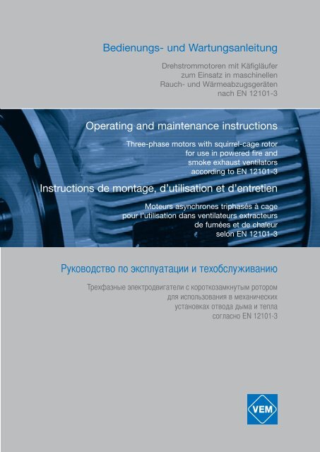
Bedienungs- und Wartungsanleitung<br />
Drehstrommotoren mit Käfigläufer<br />
zum Einsatz in maschinellen<br />
Rauch- und Wärmeabzugsgeräten<br />
nach EN 12101-3<br />
Operating and maintenance instructions<br />
Three-phase motors with squirrel-cage rotor<br />
for use in powered fire and<br />
smoke exhaust ventilators<br />
according to EN 12101-3<br />
Instructions de montage, d’utilisation et d’entretien<br />
Moteurs asynchrones triphasés à cage<br />
pour l’utilisation dans ventilateurs extracteurs<br />
de fumées et de chaleur<br />
selon EN 12101-3<br />
�уководство по эксплуатации и техобслуживанию<br />
�рехфазные электродвигатели с короткозамкнутым ротором<br />
для использования в механических<br />
установках отвода дыма и тепла<br />
согласно EN 12101-3
1. General<br />
To operate motors in the intended way, to maintain them correctly and to prevent damage to motors and the driven equipment the<br />
procedures laid down in the Operating and Maintenance Instructions must be followed. Especially to avoid risk of injury, the separately<br />
enclosed Safety Regulations must be adhered to strictly. Since for reasons of clarity the Operating and Maintenance Instructions<br />
cannot contain specific information with regard to all conceivable special applications and areas with special requirements, the<br />
user himself has to make appropriate protection arrangements during the installation process.<br />
The motors are designed for use in powered fire gas and smoke exhaust fans according to EN 12101-3. The are double-feature motors<br />
for normal operating conditions and for trouble operation.<br />
Normal operation: operation at normal operating conditions according to nameplate data<br />
Ambient temperature: -20 °C up to +40 °C<br />
Site above sea level: �1000 m<br />
Differing data on the nameplate must be followed strictly. The conditions at site must be in conformity with<br />
all nameplate data.<br />
Trouble operation: A trouble case is existing, if operating conditions differ from the normal operating conditions, this is particularly<br />
valid for an incident or trouble case that is defined according to EN 12101-3 (Temperature-time classification).<br />
After an trouble case, the motors must be replaced by new ones.<br />
If the operating conditions, also without having a trouble case, differ from the normal operating conditions stated on the nameplate, a<br />
reduced lifetime and reduced suitability for trouble cases must be taken into account.<br />
The motors are destined for use in commercial/industrial plants. The use in potentially explosive areas is prohibited.<br />
2. Description<br />
The motors have been manufactured in accordance with IEC 60034-1, EN 60034-1, EN 60204-1 and other appropriate DIN standards.<br />
The details on the relevant Order Confirmation constitute the scope of supply.<br />
According to DIN EN 12101-3, the motors are classified into Classes of F200 up to F600.<br />
Fire gas temperature Period of trouble conditions Class according to EN 12101-3<br />
1 h 2 h<br />
200°C � ��� F200<br />
300°C ��� � F300<br />
400°C � ��� F400<br />
600°C ��� � F600<br />
In practical use, other periods of trouble conditions, deviating from DIN EN are required, too, these periods are coordinated to the<br />
basic Classes. The motors have, besides the standard type designation the following special markings:<br />
Special marking for sizes 63 … 132T: BRG F… Fire gas motor, Classes F200, F300, F400<br />
Special marking for sizes � 132 Application Class according to DIN EN 12101<br />
FV (former FV0) 1 h at 200 °C<br />
FV1 2 h at 200 °C F200<br />
1 h at 250 °C<br />
FV2 1 h at 300 °C F300<br />
2 h at 250 °C<br />
FV3 2 h at 300 °C<br />
1 h at 400 °C<br />
FV4-2 1,5 h at 400 °C<br />
2 h at 400 °C F400<br />
FV4-3 2h at 400°C F400<br />
FV5 (on request) 1 h at 600 °C F600<br />
FV6 (on request) 1 h at 700 °C<br />
3. Degree of protection<br />
The degree of protection of the motors is indicated on their nameplate, the degree of protection of additional devices fitted to the<br />
motor can differ from the degree of protection of the motor. This needs to be taken into consideration during the installation of the<br />
motors. If motors with cooling methods IC 411 and IC 416 are installed in the open (Protection Standard � IP 44), they should be<br />
protected against direct effects of the climate (freezing of the fan due to direct fall of rain, snow and formation of ice).<br />
4. Type of construction<br />
The type of construction of the motors is indicated on the nameplate. The motors can be used in different types of construction only<br />
with the permission of the manufacturer and if necessary after modification carried out in accordance with the manufacturer’s instructions.<br />
Especially with types of construction with vertical shaft the user has to ensure that foreign particles cannot fall into the fan cowl.<br />
5. Transport & storage<br />
If possible the motors should only be stored in closed and dry rooms. Outdoor storage under cover is permitted for a short time only<br />
and requires adequate protection against all harmful effects of the climate. The motors also have to be protected against mechanical<br />
damage. Never transport or store motors resting on their fan cowls. The eye bolts of the motors together with appropriate lifting tackle<br />
must be used for transport. The eye bolts are intended for the lifting of the motors only, without any additional parts such as bed<br />
plates, gears etc. If eye bolts are removed after installation, the tapped holes must be blanked off permanently according to the degree<br />
of protection.
6. Removal of the transport locking<br />
On motors with transport safety device (roller bearing), the hexagon head screw provided for the fastening of the transport safety<br />
device is to be loosened and taken off together with the transport safety device. Subsequently the bearing cover bolt packed in a bag<br />
inside the terminal box is to be screwed into the bearing cover. If it is necessary for the motor type the bag will also contain a lock<br />
washer that is to be placed onto the bearing cover bolt before screwing it into the bearing end shield.<br />
7. Installation and fitting<br />
Since during normal operation of electric motors, temperatures in excess of 100 °C can occur on their surface, any contact with them<br />
must be prevented if the motors are installed in accessible areas. Because of this temperature sensitive parts must never be fitted to<br />
them or have contact with them. In types of construction IM B14 and IM B34 it must be ensured that the maximum allowed screw<br />
depth specified in the following table is not exceeded. For the flange type given in the table, the thread holes are through holes.<br />
If a motor in type of construction IM B34 is used without flange-attached components, the user has to close the through holes in an<br />
appropriate way to maintain the respective degree of protection.<br />
Flange type acc. to DIN 42948 Flange type acc. to DIN EN 50347 Screw-in depth in mm<br />
C80 FT65 8<br />
C90 FT75 8<br />
C105 FT85 8,5<br />
C120 FT100 8,5<br />
C140 FT115 10<br />
C160 FT130 10<br />
C200 FT165 12<br />
C250 FT215 13<br />
If a motor of type IMB34 without flanged attachments is used, the user has to take appropriate measures at the through holes to<br />
maintain the specified degree of protection.<br />
Vent holes must be kept free and the minimum distances stated in the dimensional drawings must be maintained so that the flow of<br />
cooling air is not obstructed. Care must be taken that the discharged warmed up cooling medium is not sucked up again.<br />
The key in the shaft end is secured by the shaft protective sleeve for transport and storage only. Because of the danger that the key<br />
may be thrown aside, a start-up or a trial run with the key protected by the shaft sleeve only is strictly forbidden.<br />
Transmission elements (such as couplings, pinions, hubs or belt pulleys) should be drawn onto the shaft by means of pull-on devices<br />
or by heating-up the part to be drawn onto the shaft. For the purpose of drawing the transmission components onto the shaft, the<br />
shaft ends are provided with tapped centring holes according to DIN 332 Part 2. Transmission components must never be driven onto<br />
the shaft using hammer blows because the shaft, the bearings and other components of the motor could be damaged. All components<br />
that are to be fitted to the shaft end must be balanced dynamically according to the balancing system of the motor (full or half<br />
key). The rotors of the motor are balanced with half key; this is indicated by the letter H after the serial number on the nameplate.<br />
Motors with letter F after the serial number are balanced on special request with full key. If possible the motors are to be installed in<br />
such a way that they are free from vibrations. With precision balanced motors special instructions are to be followed. When the installation<br />
is completed the user must ensure protection of movable parts and safety of operation.<br />
Direct coupling to the driven machine requires a particularly accurate alignment. The shafts of both machines must be in alignment.<br />
The shaft height is to be adjusted to that of the driven machine using appropriate shims. Belt drives put a lot of stress on the motor<br />
because of relatively high radial forces. When dimensioning belt drives, apart from the instructions and calculation programmes issued<br />
by the manufacturers of the belts, it must be ensured that the radial force permissible at the shaft end of the motor as stated in<br />
our data is never exceeded by the pull and pre-tensioning of the belt. When pre-tensioning the belt during installation the instructions<br />
of the belt manufacturers must be strictly adhered to.<br />
8. Insulation check<br />
When the motor is first commissioned and especially after extended storage, the insulation resistance of the winding is to be measured<br />
to earth and between phases. The test must be made with dc voltage at the design voltage level, but not lower than 500 V. During<br />
and immediately after the measurements dangerous voltages are present at the terminals. Therefore never touch the terminals<br />
and follow the operating instructions of the insulation resistance meter closely! Depending on the rated voltage U N, the following<br />
minimum values must be maintained with a winding temperature of 25 °C:<br />
Rated Power PN / kW Insulation Resistance referred to Rated Voltage / k�/V<br />
1 < PN � 10 6.3<br />
10 < PN � 100 4<br />
100 < PN 2.5<br />
If the minimum values are lower, the winding must be dried properly until the insulation resistance corresponds to the required value.<br />
9. Commissioning<br />
Please follow the Safety Regulations closely.<br />
All work is to be carried out only when there is no voltage on the motor. The installation must be carried out according to the valid<br />
regulations by qualified skilled personnel.<br />
Initially the mains conditions (voltage and frequency) must be compared with the data on the nameplate of the motor. The dimensions<br />
of the connecting cables must be adjusted in line with the rated currents of the motor.<br />
The connection points of the motor are marked in accordance with DIN EN 60034-8 (DIN VDE 0530 Part 8). In Section 18 of these<br />
instructions the most common circuit diagrams for three phase motors in basic design are provided, according to which the connection<br />
will be implemented. For all other versions, the special circuit diagrams are glued to the inside of the terminal<br />
box cover or placed in the terminal box. An additional terminal box can be provided for the connection of auxiliary and protection devices<br />
(e.g. anti-condensation heaters); the same regulations apply as for the main terminal box.<br />
Always start the motors with an over-current protection device that is set in accordance with the relevant nominal values of the motor<br />
(� 1.05 I nom). Otherwise warranty claims with respect to damaged windings become void. Before the motor is connected for the first<br />
time it is recommended to check the insulation resistances between winding and earth and between phases (see Section 8). After
prolonged storage it is absolutely essential that the insulation resistance is measured. Before coupling the motor to the driven machine,<br />
check the direction of rotation of the motor to prevent possible damage being caused to the driven machine. If the mains supply<br />
with the phase sequence L1, L2 and L3 is to be wired to the connection points U, V, W, the motor is rotating clockwise looking at the<br />
shaft end. The direction of rotation can be changed by swapping the connections between 2 phases. For the permissible tightening<br />
torques for the terminal board bolts refer to the table below:<br />
Terminal Board Connecting Bolt Thread Permissible Tightening Torque in Nm<br />
16 A M4 1.2 + 0.5<br />
25 A M5 2.5 � 0.5<br />
63 A M6 4 � 1<br />
100 A M8 7.5 � 1.5<br />
200 A M10 12.5 � 2.5<br />
400 A M12 20 � 4<br />
630 A M16 30 � 4<br />
Before closing the terminal box make absolutely sure that:<br />
- the connection has been made in accordance with the wiring diagram<br />
- all terminal box connections are tightened<br />
- all minimum values of air paths are maintained (larger than 8 mm up to 500 V, larger than 10 mm up to 750 V, larger than 14 mm<br />
up to 1000 V)<br />
- the interior of the terminal box is clean and free from foreign particles<br />
- unused cable entries are blanked off and the threaded plugs with seals are tightened<br />
- the seal in the terminal box cover is clean and tightly glued and all sealing surfaces are in the correct state to ensure that the<br />
relevant degree of protection is maintained.<br />
-<br />
Before starting up the motor check that all safety regulations are strictly adhered to, that the machine is correctly installed and aligned,<br />
that all fixing parts and earth connections are tightened, that the auxiliary and additional devices are functionally and correctly connected<br />
and if a second shaft end is fitted that the key is secured against being thrown aside.<br />
If possible the motor is to be connected without load. If the motor is running smoothly and without any abnormal noise, the load of the<br />
driven machine is to be applied onto the motor. When the motor is started up it is recommended to monitor the current consumption if<br />
the motor is loaded with its driven machine so that any possible overloads and asymmetries occurring in the mains can be recognised<br />
immediately.<br />
Please always observe the Safety Regulations during operation of the motor and when switching it off.<br />
10. Maintenance<br />
You are once again referred to the Safety Regulations, in particular to insulation, to securing against reconnection, to checking<br />
whether all components connected to a voltage source are in dead state.<br />
If it is necessary to disconnect the motor from the mains for maintenance work particular care must be taken to ensure that any possibly<br />
existing auxiliary circuits (e.g. anti-condensation heaters, forced ventilators, brakes) are also disconnected from the mains.<br />
If the motor is to be dismantled during maintenance work, the sealing compound on the centring shoulders is to be removed. When<br />
re-assembling the motor these need to be re-sealed using a suitable motor sealing compound. Existing copper sealing washer must<br />
always be refitted.<br />
11. Draining of condensation water<br />
On installation sites where formation of dew and thus occurrence of condensation water can be expected inside the motor, the accumulated<br />
condensation water has to be drained at regular intervals through the opening at the lowest point of the end shield. Subsequently<br />
the opening must be closed up again.<br />
12. Motors with thermal winding protection<br />
A continuity test of the thermistor sensor circuit using a test lamp, a hand generator and such like is strictly prohibited because this<br />
would destroy the sensors immediately. If it becomes necessary to verify the cold resistance of the sensor circuit (at approx. 20 °C)<br />
then the measuring voltage must never exceed 2.5 V DC. It is recommended to carry out the measurement using a Wheatstone<br />
bridge with a 4.5 V DC supply voltage. The cold resistance of the sensor circuit must never exceed 810 ohms; a measurement of the<br />
hot resistance is not necessary. With motors that are fitted with thermal winding protection, care must be taken that when the thermal<br />
winding protection has been tripped, and after cooling down of the motor, no hazards can occur due to spurious automatic reconnection.<br />
When a trouble case arises, then the thermal winding protection must be disabled immediately!
13. Bearings and lubrication<br />
13.1 General<br />
VEM motors are equipped with antifriction bearings of well-known manufacturers. The bearings have a nominal service life of at least<br />
20,000 hours for maximum permissible load conditions. For motors without additional axial loading, the nominal service life is 40,000<br />
hours for direct coupling and a horizontal installation position.<br />
The following versions are shown in the bearing arrangement tables:<br />
Fixed bearing, Drive-end Permanent lubrication<br />
Without fixed bearing (floating bearing) Relubricating device<br />
as well as the<br />
Antifriction bearing assignments Disc spring and wave washer assignments<br />
V-type rotary seal assignments Graphical depiction of the bearing arrangements.<br />
The respective flat grease nipples may be noted from the tables in the dimensional drawings. Motors in standard design with two<br />
deep-groove ball bearings have bearings which are set by means of disc springs or wave washers.<br />
The most important requirement for achieving the nominal bearing service life consists of proper lubrication, i.e. use of the proper type<br />
of grease for each operational situation, use of the correct quantity of grease, and maintenance of the regreasing intervals.<br />
Frame sizes 71 - 160 are equipped with lifetime-lubricated bearings. These bearings must be replaced promptly in accordance with<br />
the grease lifetime interval. For motors in frame size 180 and larger the bearings must be regreased promptly in accordance with the<br />
grease lifetime interval so that the nominal bearing service life can be achieved. Under normal operating conditions, the grease charge<br />
provides 10,000 service hours with two pole design and 20,000 service hours with four or more pole design without regreasing.<br />
Versions with regreasing devices provide 2.000 or 4.000 service hours respectively under normal operating conditions. Please observe<br />
chapter 13.5 for detailed information concerning the usable grease. After five regreasing operations the used grease must be<br />
removed from the grease chamber of the external bearing cover. For information on bearing sizes, type and quantity of grease and<br />
regreasing intervals please refer to the additional plate affixed to the motor.<br />
13.2 Bearing loading and shaft end loading<br />
Due to the international standardisation of asynchronous motors, dimensioning of the bearing arrangement and shaft is only variable<br />
within limits; a constructional optimum has thus been selected.<br />
13.3 Admissible shaft end loading<br />
The size of the permissible shaft end loading is determined using the following main criteria:<br />
- permissible bending of the shaft<br />
- shaft fatigue strength<br />
- bearing service life<br />
The admissible shaft end loading (radial and axial forces) is based on a bearing service life of 20,000 hours and resistance to fatigue<br />
of >2.0.<br />
The loading diagram is specified in the following illustration:<br />
F r = radial shaft end loading<br />
F a = axial shaft end loading<br />
l = length of the shaft end<br />
x = distance of the application point F r from the shaft shoulder<br />
The type-related data for the permissible axial shaft end loading F a and the permissible radial shaft end loading F r0.5 (at the application<br />
point x : l = 0.5), F r1.0 (at the application point x : l = 1.0) for the basic version in horizontal mounting position of the motors in the<br />
Classes F200, F300 and F400, are specified in the following tables.<br />
The permissible radial forces are depicted as a function of the position of the application point on the shaft end for motors in horizontal<br />
mounting position of the motor .<br />
The permissible forces given are valid for practically vibration-free mounting of the motors.<br />
The shaft loading for frame sizes 315 L and LX and frame size 355 can be verified by the manufacturer on request.<br />
The loadings F r and F a are generally dependent on the used transmission elements, fans etc., i.e. on the axial and radial forces arising<br />
from these elements, including their weights.<br />
In practice, the radial force F r does not always act at x : l =0.5. The conversion of the permissible radial force within the range x : l =<br />
0.5 up to x : l =1.0 can be done by linear interpolation.<br />
If the calculated shaft loadings exceed the permissible ones, the drive elements must be changed.<br />
Generally, care must be taken that the resulting load application point of F r will not be outside the shaft end. If a solution has still not<br />
been found, the manufacturer would be happy to check special constructions which can be used to deal with problems of this kind.
13.4 Bearing arrangements and their graphical depiction<br />
13.4.1 Series K1.R, K2.R, K22R, Fire gas versions F200, F300 and F400<br />
Horizontal type of mounting<br />
Type D-end N-end Figure Fixed<br />
bearing<br />
Antifriction<br />
bearing<br />
V-Ring<br />
�-Ring<br />
Nilos ring<br />
K21R 71 6202 6202 - 35<br />
K21R 80 6204 6204 47<br />
K21R 90 6205<br />
K21R 100 6205 52 1 2 none<br />
K21R 100 LX 6206 - - -<br />
K21R 112 M 6206 62<br />
K21R 132 S2, 4 T 6208 -<br />
K11R 132 S, SX2, M6, 8 6208 RS C3 6208 Z AV 80 6207 M C3 35A<br />
K11R 132 M4, MX6 6308 RS C3 6308 Z AV 90<br />
K11R 160 M, MX8<br />
K11R 160 MX2, L<br />
6309 RS C3 - 6309 Z AV 100 6308 M C3 40A 3 5<br />
K11R 180 M4, L6, 8 6310 RS C3 6310 Z AV 110 6309 M C3 45A<br />
K11R 180 M2, L4 6310 C3 50A<br />
K11R 200 L, LX6 6310 M C3 50A<br />
K11R 200 LX2 6312 C3 60A 130<br />
K11R 225 M2<br />
K11R 225 S4, 8, M4, 6, 8<br />
6312 M C3 60A<br />
K11R 250 M2 6313 C3 65A 140 - 6 8 N-<br />
K11R 250 M4, 6, 8 - 6313 M C3 65A end<br />
K11R 280 S2, M2 6314 C3 70A 150<br />
K11R 280 S4,6,8, M4, 6, 8 6314 M C3 70A<br />
K11R 315 S2, M2<br />
K11R 315 S4, 6, 8, M4, 6, 8<br />
6316 C3 80A 170<br />
K11R 315 MX2 6317 C3 RB85 6316 M C3 80A<br />
K11R 315 MX4, 6, 8 6220 C3 RB100 180 13 16<br />
K11R 315 MY2 6317 C3 RB85<br />
K11R 315 MY4, 6, 8 6320 C3 - RB100 215<br />
K11R 315 L2, LX2 6317 C3 RB85 180 6317 M C3 85A 18 19<br />
K11R 315 L4, 6, 8, LX4, 6, 8 6320 C3 RB100 215<br />
Wave<br />
washer<br />
K22R 355 ... 2pol e<br />
6317 C3 RB85 180<br />
K22R 355 ... 4-, 6-, 8-pole 6324 C3 120S - 260<br />
Sizes 71 – 132 S...T: always with radial sealing rings, F200 bearing 62.. Z C3, F300/400 bearing 62.. 2Z N C4 S1<br />
For F400 antifriction bearings N-end from 6207 up to 6317 with brass cage “M”<br />
From size K21R 315 MX standard version with relubricating device<br />
Series K20R/K10R<br />
Type D-end N-end Figure<br />
Antifriction<br />
bearing<br />
V-Ring<br />
�-Ring<br />
Nilos-Ring<br />
Wave<br />
washer<br />
Disc spring<br />
Disc spring<br />
Antifriction<br />
bearing<br />
Antifriction<br />
bearing<br />
V-Ring<br />
Wave<br />
washer<br />
V-Ring<br />
D-end<br />
Wave<br />
washer<br />
D-end<br />
K20R 63 6202 6202 35<br />
K20R 71 6204 6204 47<br />
K20R 80 -<br />
K20R 90 6205 - 6205 52<br />
K20R 100 6206 6206 62 none<br />
K10R 112 M2, 4, 6, 8 - - -<br />
K10R 112 MX6, 8 6207 RS C3 6207 Z AV 72 6207 M C3 35A<br />
K10R 132 S, M 6308 RS C3 6208 Z AV 90 6308 M C3 40A 3 5<br />
K10R 160 S, M 6310 RS C3 6210 Z AV 6309 M C3 45A<br />
K10R 180 S2, M2 6310 C3 50A 110<br />
K10R 180 S4, 6, 8, M4, 6, 8 6310 M C3 50A<br />
K10R 200 M2, L2 6312 C3 60A 130<br />
K10R 200 M4, 6, 8, L4, 6, 8 6312 M C3 60A<br />
K10R 225 M2 6313 C3 65A 140<br />
K10R 225 M4, 6, 8 6313 M C3 65A<br />
K10R 250 S2, M2 6314 C3 70A 150 - 6 8<br />
K10R 250 S4, 6, 8, M4, 6, 8 - - 6314 M C3 70A<br />
K10R 280 S2, M2 6316 C3 80A 170 N-<br />
K10R 280 S4,6,8, M4, 6, 8 end<br />
K10R 315 S2 6317 C3 RB85 6316 M C3 80A<br />
K10R 315 S4, 6, 8 6220 C3 - RB100 180 13 16<br />
K10R 315 M2, L2 6317 C3 RB85<br />
K10R 315 M4, 6, 8, L4, 6, 8 6320 C3 RB100 215 6317 M C3<br />
N-end<br />
N-end<br />
85A 18 19<br />
Sizes 63 – 132 S...T: always with radial sealing rings, F200 bearing 62.. Z C3, F300/400 bearing 62.. 2Z N C4 S1<br />
For F400 antifriction bearings N-end from 6207 up to 6317 with brass cage “M”<br />
From size K10R 315 standard version with relubricating device<br />
Fixed bearing
13.4.2 Admissible axial and radial loads for series K21R, K11R, K22R<br />
Fire gas version F200, F300 and F400,<br />
Basic version horizontal shaft (figures in kN)<br />
Size Fa Fr 0,5 Fr 1,0 Fa Fr 0,5 Fr 1,0<br />
Normal Trouble Normal<br />
operation operation operation Trouble Normal Trouble<br />
operation operation operation<br />
Synchronous speed 3000 rpm – 2pole version<br />
Normal Trouble Normal Trouble Normal Trouble<br />
operation operation operation operation operation operation<br />
Synchronous speed 1500 rpm – 4pole version<br />
K21R 71 0,185 0,07 0,20 0,23 0,12 0,26<br />
K21R 80 0,30 0,13 0,31 0,38 0,20 0,43<br />
K21R 90 0,305 0,13 0,36 0,42 0,20 0,46<br />
K21R 100 0,42 0,15 - 0,40 - - 0,56 0,23 - 0,50 - -<br />
K21R 100/112 0,46 0,17 0,46 0,58 0,28 0,58<br />
K21R 132T 0,60 0,22 0,60 0,84 0,28 0,73<br />
K11R 132 S 0,60 0,40 0,92 0,60 0,82 0,52 0,84 0,53 1,16 0,73 1,03 0,65<br />
K11R 132 SX 0,60 0,40 0,92 0,60 0,82 0,52 - - - - - -<br />
K11R 132 M - - - - - - 1,28 0,80 1,64 1,03 1,44 0,90<br />
K11R 160 M 0,88 0,55 1,60 1,00 1,44 0,90 1,20 0,75 2,00 1,25 1,76 1,10<br />
K11R 160 MX 1,20 0,75 1,84 1,15 1,64 1,03 - - - - - -<br />
K11R 160 L 1,20 0,75 1,84 1,15 1,64 1,03 1,52 0,95 2,40 1,50 2,16 1,35<br />
K11R 180 M 1,20 0,75 1,92 1,20 1,72 1,08 1,52 0,95 2,40 1,50 2,16 1,35<br />
K11R 180 L - - - - - - 2,00 1,25 2,48 1,55 2,20 1,38<br />
K11R 200 L 1,44 0,90 2,56 1,60 2,24 1,40 1,92 1,20 3,20 2,00 2,80 1,75<br />
K11R 200 LX 2,00 1,25 2,56 1,60 2,24 1,40 - - - - - -<br />
K11R 225 S - - - - - - 2,40 1,50 3,52 2,20 3,12 1,95<br />
K11R 225 M 2,00 1,25 2,56 1,60 2,24 1,40 2,40 1,50 3,52 2,20 3,12 1,95<br />
K11R 250 M 2,00 1,25 2,72 1,70 2,40 1,50 2,80 1,75 3,92 2,45 3,44 2,15<br />
K11R 280 S 2,80 1,75 4,04 2,53 3,68 2,30 3,60 2,25 6,00 3,75 5,44 3,40<br />
K11R 280 M 3,20 2,00 4,08 2,60 3,68 2,30 3,60 2,25 6,00 3,75 5,52 3,45<br />
K11R 315 S 3,60 1,80 4,72 2,36 4,32 2,16 4,80 2,40 5,84 2,92 5,36 2,68<br />
K11R 315 M 3,60 1,80 4,72 2,36 4,32 2,16 4,80 2,40 5,84 2,92 5,44 2,72<br />
K11R 315 MX 3,60 1,80 4,80 2,40 4,48 2,24 4,00 2,00 8,00 4,00 7,52 3,76<br />
K11R 315 MY<br />
K11R 315L, LX<br />
4,80 2,40 7,68 3,84 7,20 3,60 4,80 2,40<br />
Load data on request<br />
7,68 3,84 7,20 3,60<br />
K22R 355M, MX, LY, L Load data on request<br />
The named data are valid for fire gas motors with horizontal shaft, for motors with vertical shaft load data on request<br />
The loading circumstances for normal operation and for trouble operation must be checked with respect to the admissible axial loads<br />
F a and radial loads F r. The really acting loads must, for every operational case, not exceed the admissible ones.<br />
13.4.3 Admissible axial and radial loads for series K10R, K20R<br />
Fire gas version F200, F300 and F400,<br />
Basic version horizontal shaft (figures in kN)<br />
Size Fa Fr 0,5 Fr 1,0 Fa Fr 0,5 Fr 1,0<br />
Normal Trouble Normal<br />
operation operation operation Trouble Normal Trouble<br />
operation operation operation<br />
Synchronous speed 3000 rpm – 2pole version<br />
Normal Trouble Normal Trouble Normal Trouble<br />
operation operation operation operation operation operation<br />
Synchronous speed 1500 rpm – 4pole version<br />
K20R 63 0,185 0,07 0,20 0,23 0,12 0,26<br />
K20R 71 0,30 0,13 0,31 0,38 0,20 0,43<br />
K20R 80 0,305 0,13 - 0,36 - - 0,42 0,20 - 0,46 - -<br />
K20R 90 0,42 0,15 0,40 0,56 0,23 0,50<br />
K20R 100 0,46 0,17 0,46 0,58 0,28 0,58<br />
K20R 112 M 0,60 0,376 0,88 0,55 0,80 0,50 0,84 0,525 1,08 0,675 0,952 0,595<br />
K10R 132 S - - - - - - 0,64 0,32 1,56 0,78 1,36 0,68<br />
K10R 132 M 0,56 0,28 1,28 0,64 1,12 0,56 0,64 0,32 1,56 0,78 1,36 0,68<br />
K10R 160 S 1,36 0,68 1,84 0,92 1,60 0,80 1,52 0,76 2,40 1,20 2,16 1,08<br />
K10R 160 M 1,20 0,60 1,84 0,92 1,60 0,80 1,52 0,76 2,40 1,20 2,16 1,08<br />
K10R 180 S 1,36 0,68 1,84 0,92 1,60 0,80 1,92 0,96 3,28 1,64 2,88 1,44<br />
K10R 180 M 1,36 0,68 1,84 0,92 1,60 0,80 1,92 0,96 3,28 1,64 2,88 1,44<br />
K10R 200 M 1,92 0,96 2,56 1,28 2,24 1,12 2,40 1,20 3,52 1,76 3,12 1,56<br />
K10R 200 L 1,92 0,96 2,56 1,28 2,24 1,12 2,40 1,20 3,52 1,76 3,12 1,56<br />
K10R 225 M 1,52 0,76 2,00 1,00 1,76 0,88 2,80 1,40 4,08 2,04 3,60 1,80<br />
K10R 250 S 2,80 1,40 4,04 2,02 3,68 1,84 3,60 1,80 6,00 3,00 5,44 2,72<br />
K10R 250 M 3,20 1,60 4,08 2,04 3,68 1,84 3,60 1,80 6,00 3,00 5,52 2,76<br />
K10R 280 S 3,60 1,80 4,72 2,36 4,32 2,16 4,80 2,40 5,84 2,92 5,36 2,68<br />
K10R 280 M 3,60 1,80 4,72 2,36 4,32 2,16 4,80 2,40 5,84 2,92 5,44 2,72<br />
K10R 315 S 3,60 1,80 4,80 2,40 4,48 2,24 4,00 2,00 8,00 4,00 7,52 3,76<br />
K10R 315 M 4,80 2,40 7,68 3,84 7,20 3,60 4,80 2,40 7,68 3,84 7,20 3,60<br />
K10R 315 L Load data on request<br />
The named data are valid for fire gas motors with horizontal shaft, for motors with vertical shaft load data on request<br />
The loading circumstances for normal operation and for trouble operation must be checked with respect to the admissible<br />
axial loads Fa and radial loads Fr. The really acting loads must, for every operational case, not exceed the admissible<br />
ones.
13.4.4 Series Y21O, Y22O, Y20O, Fire gas versions F200, F300 and F400<br />
Types of mounting IM B5, IM V1, IM V3, IM B35, IM V15, IM V36, degree of protection IP 55<br />
Type Shaft end Bearings<br />
d x l D-end N-end<br />
in mm Standard Inverter feeding<br />
Synchronous speed 1500 rpm – 4pole version<br />
Y21O 280 S4 Y20O 250 S4 70x140 2 x 7316B MB UA 6316 M C3 6314 M C3 VL0241<br />
Y21O 280 M4 Y20O 250 M4 70x140 2 x 7316B MB UA 6316 M C3 6314 M C3 VL0241<br />
Y21O 315 S4 Y20O 280 S4 80x140 2 x 7317B MB UA 6316 M C3 6316 M C3 VL0241<br />
Y21O 315 M4 Y20O 280 M4 80x140 2 x 7317B MB UA 6316 M C3 6316 M C3 VL0241<br />
Y21O 315 MX4 Y20O 315 S4 80x140 2 x 7317B MB UA 6316 M C3 6316 M C3 VL0241<br />
Y21O 315 MY4 Y20O 315 M4 80x140 2 x 7320B MB UA 6317 M C3 6317 M C3 VL0241<br />
Y21O 315 L4 Y20O 315 L4 80x140 2 x 7320B MB UA 6317 M C3 6317 M C3 VL0241<br />
Y21O 315 LX4 Y20O 315 LX4 80x140 2 x 7320B MB UA 6317 M C3 6317 M C3 VL0241<br />
Y22O 355 MX4 100x210 2 x 7324B MB UA 6317 M C3 6317 M C3 VL0241<br />
Y22O 355 LY4 100x210 2 x 7324B MB UA 6317 M C3 6317 M C3 VL0241<br />
Synchronous speed 1000 rpm – 6pole version<br />
Y21O 280 S6 Y20O 250 S6 70x140 2 x 7316B MB UA 6314 M C3 6314 M C3 VL0241<br />
Y21O 280 M6 Y20O 250 M6 70x140 2 x 7316B MB UA 6314 M C3 6314 M C3 VL0241<br />
Y21O 315 S6 Y20O 280 S6 80x140 2 x 7317B MB UA 6316 M C3 6316 M C3 VL0241<br />
Y21O 315 M6 Y20O 280 M6 80x140 2 x 7317B MB UA 6316 M C3 6316 M C3 VL0241<br />
Y21O 315 MX6 Y20O 315 S6 80x140 2 x 7317B MB UA 6316 M C3 6316 M C3 VL0241<br />
Y21O 315 MY6 Y20O 315 M6 80x140 2 x 7320B MB UA 6317 M C3 6317 M C3 VL0241<br />
Y21O 315 L6 Y20O 315 L6 80x140 2 x 7320B MB UA 6317 M C3 6317 M C3 VL0241<br />
Y21O 315 LX6 Y20O 315 LX6 80x140 2 x 7320B MB UA 6317 M C3 6317 M C3 VL0241<br />
Y22O 355 M6 100x210 2 x 7324B MB UA 6317 M C3 6317 M C3 VL0241<br />
Y22O 355 MX6 100x210 2 x 7324B MB UA 6317 M C3 6317 M C3 VL0241<br />
Synchronous speed 750 rpm – 8pole version<br />
Y21O 315 S8 Y20O 280 S8 80x140 2 x 7317B MB UA 6316 M C3 6316 M C3 VL0241<br />
Y21O 315 M8 Y20O 280 M8 80x140 2 x 7317B MB UA 6316 M C3 6316 M C3 VL0241<br />
Y21O 315 MX8 Y20O 315 S8 80x140 2 x 7317B MB UA 6316 M C3 6316 M C3 VL0241<br />
Y21O 315 MY8 Y20O 315 M8 80x140 2 x 7320B MB UA 6317 M C3 6317 M C3 VL0241<br />
Y21O 315 L8 Y20O 315 L8 80x140 2 x 7320B MB UA 6317 M C3 6317 M C3 VL0241<br />
Y21O 315 LX8 Y20O 315 LX8 80x140 2 x 7320B MB UA 6317 M C3 6317 M C3 VL0241<br />
Y22O 355 M8 100x210 2 x 7324B MB UA 6317 M C3 6317 M C3 VL0241<br />
Y22O 355 MX8 100x210 2 x 7324B MB UA 6317 M C3 6317 M C3 VL0241<br />
Y22O 355 LY8 100x210 2 x 7324B MB UA 6317 M C3 6317 M C3 VL0241<br />
13.4.5 Admissible axial and radial loads for series Y21O, Y22O, Y20O<br />
Fire gas version F400<br />
Basic version for horizontal and vertical shafts ( Figures in N)<br />
Motor type Admissible load, horizontal type of mounting Admissible load, vertical type of mounting<br />
axial radial axial radial<br />
Synchronous speed 1500 rpm – 4pole version<br />
Y21O 280 S4 Y20O 250 S4 1450 3800 5250 390<br />
Y21O 280 M4 Y20O 250 M4 1600 3800 5400 390<br />
Y21O 315 S4 Y20O 280 S4 1480 5600 7080 570<br />
Y21O 315 M4 Y20O 280 M4 2500 5600 8100 570<br />
Y21O 315 MX4 Y20O 315 S4 3000 5600 8600 570<br />
Y21O 315 MY4 Y20O 315 M4 3400 5600 9000 570<br />
Y21O 315 L4 Y20O 315 L4 4000 5600 9600 570<br />
Y21O 315 LX4 Y20O 315 LX4 4000 5600 9600 570<br />
Y22O 355 MX4 5000 5600 10600 570<br />
Y22O 355 LY4 5500 5600 11100 570<br />
Synchronous speed 1000 rpm – 6pole version<br />
Y21O 280 S6 Y20O 250 S6 800 3800 4600 280<br />
Y21O 280 M6 Y20O 250 M6 1050 3800 4850 280<br />
Y21O 315 S6 Y20O 280 S6 1200 5600 6800 410<br />
Y21O 315 M6 Y20O 280 M6 2000 5400 7400 390<br />
Y21O 315 MX6 Y20O 315 S6 2850 7900 10750 570<br />
Y21O 315 MY6 Y20O 315 M6 3500 7900 11400 570<br />
Y21O 315 L6 Y20O 315 L6 3650 7900 11550 570<br />
Y21O 315 LX6 Y20O 315 LX6 3800 7900 11700 570<br />
Y22O 355 M6 4800 7900 12700 570<br />
Y22O 355 MX6 5350 7900 13250 570<br />
Synchronous speed 750 rpm – 8pole version<br />
Y21O 315 S8 Y20O 280 S8 1900 5700 7600 290<br />
Y21O 315 M8 Y20O 280 M8 2050 7900 9950 400<br />
Y21O 315 MX8 Y20O 315 S8 2200 7900 10100 400<br />
Y21O 315 MY8 Y20O 315 M8 2400 7900 10300 400<br />
Y21O 315 L8 Y20O 315 L8 2500 7900 10400 400<br />
Y21O 315 LX8 Y20O 315 LX8 3300 7900 11200 400<br />
Y22O 355 M8 3650 7900 11550 400<br />
Y22O 355 MX8 3800 7900 11700 400<br />
Y22O 355 LY8 4400 5700 10100 290
13.5.4 Graphic depiction to the bearing arrangements<br />
In the following figures, the versions of the different bearing arrangement are shown in detail.<br />
fi gure 1 fi gure 2 fi gure 3 fi gure 4<br />
fi gure 5 fi gure 6 fi gure 7 fi gure 8<br />
fi gure 9 fi gure 10 fi gure 11 fi gure 12<br />
fi gure 13 fi gure 14 fi gure 15 fi gure 16<br />
fi gure 17 fi gure 18 fi gure 19 fi gure 20<br />
fi gure 21 fi gure 22 fi gure 23 fi gure 24
13.5. Greasing, regreasing periods and required grease amounts<br />
The antifriction bearings of the motors in standard design are filled with antifriction bearing grease in the factory (or with sealed bearings<br />
by the bearing manufacturer) according to DIN 51825 in compliance with the table below:<br />
Type Series Lubricating Grease acc. to<br />
DIN 51825<br />
Basic grease<br />
Squirrel-cage motors FV, FV1 and FV2 KE2/3R-40 (Standard grease) Ester oil/polyurea<br />
Squirrel-cage motors K11R, K11O 132 – 315, K21R71-132..T,<br />
Synth. Hydrocar-<br />
K22R 355 and<br />
K10R, K10O 112 – 315, FV3<br />
KHC1R-30<br />
bon/organic polymer<br />
Squirrel-cage motors K11R, K11O 132 – 315, K22R 355 and<br />
PFPE /<br />
K10R, K10O 112 – 315, FV4, FV4-2, FV4-3, FV5<br />
KPFK2U-40<br />
Sodium complex<br />
Under normal load and climatic conditions, the quality of grease guarantees operation of the motor for approx. 10,000 service hours<br />
with two pole design and 20,000 service hours with multi-pole design. Unless otherwise agreed the antifriction bearing grease does<br />
not have to be refilled during this period. However, the condition of the grease should be checked occasionally even before this time<br />
limit. The indicated number of service hours is only valid for operation at rated speed. If during operation of the motor via a frequency<br />
converter the nominal speed is exceeded then the regreasing period is reduced approximately in inverse proportion to the increase in<br />
the motor speed.<br />
Regrease the bearings only after a thorough cleaning using suitable solvents. The same type of grease must be used. When replacing<br />
the grease only the equivalent types specified by the motor manufacturer can be used. Please bear in mind that the bearings<br />
should only be filled up to about 2/3 of their free space. A complete filling of the bearings and bearing covers with grease leads to<br />
increased bearing temperature and therefore to increased wear.<br />
The regreasing of bearings with a relubricating facility is carried out at the grease nipple when the motor is running using the grease<br />
quantity and regreasing intervals required for the respective motor.<br />
The used grease is collected in the grease chamber of the external bearing cover. After approx. five regreasings this old grease<br />
should be removed, e.g. as part of inspection work.<br />
When the machine is commissioned after a longer period of storage inspect the bearing grease visually and replace it if hardening<br />
and other irregularities occur. If the motors are to be commissioned more than three years after their delivery by the manufacturer<br />
then the bearing grease must always be replaced. With motors fitted with covered or sealed bearings after a storage period of four<br />
years the bearings must always be replaced with new bearings of the same type.<br />
Series K11R, K11O, K10R, K10O, K22R, K22O<br />
Series K10., Design length / Grease amount in cm<br />
K22.<br />
Pole number<br />
3 Series K11. Design length / Grease amount in cm<br />
Pole number<br />
3<br />
Size D-end N-end Size D-end N-end<br />
112 10 10 160 LX2, M2, L4, 6, 8 20<br />
132 all 17 17 180 M2, L4 23 23<br />
160 20 M4, L6, 8 20<br />
180 2 23 23 L2 - -<br />
� 4 200 LX2 31<br />
200 2 31 31 L4, 6, 8, LX 6 31 23<br />
� 4 225 M2<br />
225 2 35 M4, 6, 8, S4, 8 31<br />
� 4 35 250 M2 35<br />
250 2 41 M4, 6, 8 35<br />
� 4 41 280 2 41<br />
280 2 52 � 4 41<br />
� 4 52 2 52<br />
S2 57 � 4 52<br />
315 M2 57 MX2 57<br />
S4, 6, 8 64 52 315 MY2 57<br />
M4, 6, 8 78 MX4, 6, 8 64 52<br />
355 2 57 57 MY4, 6, 8 78 57<br />
4, 6, 8 90<br />
14. Cleaning<br />
So that the effects of cooling air are not interfered with, all parts of the motor must be cleaned at regular intervals. In the majority of<br />
cases it is sufficient to clean the machine with compressed air that is free from water and oil. Especially the vent holes and the spaces<br />
between the fins must be kept clean. It is recommended to include the electric motors in the regular routine inspections of the driven<br />
machine.<br />
15. Warranty, Repair, Spare Parts<br />
Unless expressly agreed otherwise our authorised workshops are responsible for all repairs under warranty. Any other repairs that<br />
may potentially be required can also be carried out by skilled personnel in these workshops. Details about our Customer Service<br />
network can be obtained from the manufacturer on request. Spare parts are listed in Section 19 of these Operating and Maintenance<br />
Instructions. Maintenance carried out appropriately (provided it is as described in the Section “Maintenance”) does not constitute a<br />
breach of warranty provisions. The contractual warranty liability on the part of the manufacturer is not prejudiced by this.<br />
16. Electromagnetic Compatibility<br />
The motors, as a non-independently working unit, have been checked with regard to their conformity with the EMC Standards. It is the<br />
responsibility of the equipment operator to ensure by suitable measures that the equipment and systems in their entirety comply with<br />
the relevant electromagnetic compatibility standards.
17. Trouble Shooting<br />
General mechanical and electrical faults are to be rectified according to the diagram in Section 20. All Safety Regulations must be<br />
strictly observed when rectifying faults.<br />
18. Terminal board circuits<br />
Single Speed Squirrel Cage Motor: Single Speed Squirrel Cage Motor:<br />
� low voltage Y high voltage<br />
Star Delta Switch Connection:<br />
Motors with Thermal Winding Protection<br />
Terminal board connection as above<br />
TP1 (T1)<br />
TP2 (T2)<br />
For Star Delta without bridges, connection as per the switch diagram<br />
Connection of the tripping device from the motor<br />
The connection is implemented as per the<br />
connection diagram of the tripping device
19. Construction of the motor<br />
Item No. Bezeichnung Designation<br />
1.01 Lagerschild D-Seite End shield Drive-end<br />
1.02 Lagerdeckel, D-Seite, außen Bearing cover, Drive-end, external<br />
1.03 Lagerdeckel, D-Seite, innen Bearing cover, Drive-end, internal<br />
1.04<br />
Tellerfeder / Wellfeder, D-Seite,<br />
Disc spring / wave washer, Drive-end,<br />
nicht bei Rollenlagern<br />
not for roller bearings<br />
1.05 Wälzlager D-Seite Antifriction bearing, Drive-end<br />
1.06-1 V-Ring D-Seite V-type rotary seal, Drive-end<br />
1.06-2 �-Ring D-Seite �-type rotary seal, Drive-end<br />
1.07 Flanschlagerschild Flange end shield<br />
1.08-1 Radial-Wellendichtring 1, D-Seite Radial sealing ring 1, Drive-end<br />
1.08-2 Radial-Wellendichtring 2, D-Seite Radial sealing ring 2, Drive-end<br />
1.09 Laufbuchse, D-Seite Liner, Drive-end<br />
2.01 Lagerschild N-Seite End shield Non-drive end<br />
2.02 Lagerdeckel, N-Seite, außen Bearing cover, Non-drive end, external<br />
2.03 Lagerdeckel, N-Seite, innen Bearing cover, Non-drive end, internal<br />
2.04 Wälzlager N-Seite Antifriction bearing, Non-drive end<br />
2.05 V-Ring N-Seite V-type rotary seal, Non-drive end<br />
2.06 Wellfeder N-Seite (oder D-Seite) Wave washer, Non-drive end (or Drive-end)<br />
3.01 1 Paar Motorfüße 1 pair of motor feet<br />
3.02 Lüfter Fan<br />
3.03 Lüfterhaube, Kunststoff Fan cowl, plastic<br />
3.04 Lüfterhaube, Stahlblech Fan cowl, sheet steel<br />
3.05 Lüfterhaube mit Schutzdach Fan cowl with canopy<br />
3.06 Ringschraube Lifting eye bolt<br />
4.01/4.02 Klemmenkastendeckel Terminal box cover<br />
4.03/4.04 Dichtung Klemmenkastendeckel Terminal box cover gasket<br />
4.05/4.06 Klemmenkastenunterteil Terminal box base<br />
4.07 Dichtung Klemmenkastenunterteil Terminal box base gasket<br />
4.08 Klemmenplatte Terminal plate<br />
4.09 Kabeleinführung Cable gland<br />
4.10 Verschlußschraube Screw plug for gland opening<br />
4.11 Kabeleinführung für thermischen Wicklungsschutz Cable gland for thermal winding protection<br />
4.12 Anschluß für therm. Wicklungsschutz Terminal for thermal winding protection<br />
4.13 Schelle Clamp<br />
4.14 Verschlußstücken Sealing components<br />
4.15 Zwischenplatte Adapter plate<br />
4.16 Flacher Anschlußkasten Flat terminal box<br />
4.17 Normalienbeutel Standard parts bag<br />
5.01 Läufer, komplett Rotor, complete<br />
6.01 Schleuderscheibe, D-Seite Grease thrower ring, Drive-end<br />
6.02 Schleuderscheibe, N-Seite Grease thrower ring, Non-drive end<br />
6.03 Labyrinthbuchse, D- u. N-Seite Labyrinth gland, Drive- and Non-drive end<br />
6.04 Leitscheibe, D-Seite Guide disc, Drive-end<br />
6.05 Leitscheibe, N-Seite Guide disc, Non-drive end
Three-phase asynchronous motor / Basic version K1.R/K22R 112 – 355<br />
(Example, delivered version may differ in details)
1.04<br />
1.06<br />
1.02<br />
1.04<br />
1.06<br />
1.02<br />
Non-ventilated three-phase asynchronous motor / Basic version K1.O/K22O 112 – 355<br />
(example, delivered version may differ in details)<br />
1.01<br />
1.07<br />
1.07<br />
1.01 1.03<br />
4.03<br />
4.12<br />
4.11<br />
1.05<br />
1.05<br />
1.05<br />
1.05<br />
4.07<br />
1.03<br />
4.01<br />
2.04<br />
Three-phase motors of the series Y..O have, except the terminal box location at the N-end, the same design<br />
4.02<br />
4.04<br />
4.06<br />
4.07<br />
4.08<br />
4.05<br />
4.09<br />
3.06<br />
3.01<br />
4.15<br />
4.03<br />
5.01<br />
2.03<br />
4.13<br />
4.14<br />
2.04<br />
2.01<br />
2.01<br />
2.05<br />
2.02
20. Trouble Shooting<br />
20.1 Electrical Faults<br />
Motor doesn’t start<br />
Motor runs up heavily<br />
Humming noise during start<br />
Humming noise during operation<br />
Hum in time of the double slip frequency<br />
Excessive heating up in no-load operation<br />
Excessive heating up at rated output<br />
Excessive heating up of individual winding sections<br />
Possible cause of fault Remedial measure<br />
��������������<br />
�����������<br />
Overload Decrease the load<br />
������������<br />
�����������<br />
Interruption of a phase in the supply conductor<br />
Check the switch and the supply conductor<br />
����������� Interruption of a phase in the supply conductor<br />
��������������<br />
�����������<br />
after switching-on Check the switch and the supply conductor<br />
������������<br />
�����������<br />
Mains voltage too low, frequency too high Check the mains conditions<br />
������������<br />
�����������<br />
Mains voltage too high, frequency too low Check the mains conditions<br />
���������������<br />
�����������<br />
Stator winding misconnected Check the winding conditions<br />
��������������<br />
�����������<br />
Turn-to-turn fault Check the winding and the insulation resistance,<br />
repair in authorised service workshop<br />
��������������<br />
�����������<br />
Phase-to-phase short circuit Check the winding and the insulation resistance,<br />
repair in authorised service workshop<br />
������������ Interruption in the squirrel cage winding Repair in authorised service workshop
20.2 Mechanical Faults<br />
Dragging noise<br />
Excessive heating up<br />
Strong vibrations<br />
Bearing heats up excessively<br />
Bearing noises<br />
Possible cause of fault Remedial measure<br />
�������������� Rotary parts are dragging Determine the cause, re-align parts<br />
�����������<br />
������������ Air supply reduced Check the ventilation passages<br />
�����������<br />
������������ Unbalance of the rotor Take rotor off, re-balance it<br />
�����������<br />
������������ Rotor not circular, shaft deformed Take rotor off, co-ordinate further measures with the manufacturer<br />
�����������<br />
������������ Imperfect alignment Align motor & driven machine, check the coupling<br />
�����������<br />
������������ Unbalance of the coupled machine Re-balance coupled machine<br />
�����������<br />
������������ Shocks from the coupled machine Check the coupled machine<br />
�����������<br />
������������ Irregularities from the gear Check and repair the gear<br />
�����������<br />
������������ Resonance with the foundation Stiffen the foundation after consultation<br />
�����������<br />
������������ Changes in the foundation Determine the cause, eliminate it and re-align the machine<br />
�����������<br />
������������ Too much grease in the bearing Remove excess grease<br />
�����������<br />
������������ Coolant temperature over 40 °C Regrease bearing with suitable grease<br />
�����������<br />
������������ V-type rotary seal or gamma ring is drag-<br />
ging<br />
Replace V-type rotary seal or gamma ring, maintain the<br />
prescribed installation clearance<br />
�����������<br />
������������� Lubrication insufficient Lubricate according to instructions<br />
�����������<br />
������������� Bearing is corroded Replace bearing<br />
�����������<br />
������������� Bearing clearance too small Use bearing with larger bearing clearance<br />
�����������<br />
������������ Bearing clearance too large Use bearing with smaller bearing clearance<br />
�����������<br />
������������ Chatter marks in the bearing track Replace bearing<br />
�����������<br />
������������ Standstill marks Replace bearing<br />
�����������<br />
������������ Cylindrical roller bearing operated at low<br />
load<br />
Change the bearing according to manufacturer’s instructions<br />
�����������<br />
������������ Coupling pushes or pulls Re-align motor & driven machine<br />
�����������<br />
������������ Belt tension too high Adjust the belt tension according to instructions<br />
�����������<br />
������������� Bearing not aligned or stressed Check the bearing bore, consult the manufacturer<br />
Note:<br />
We make all efforts to better our products continuously.<br />
Versions, technical data and figures could be changed therefore.<br />
They are always not binding before written confirmation by the supply factory.
VEM motors GmbH<br />
Carl-Friedrich-Gauß-Straße 1<br />
D-38855 Wernigerode<br />
Telefon: +49 - (0) 39 43 - 68 - 0<br />
Telefax: +49 - (0) 39 43 - 68 - 21 20<br />
E-Mail: motors@vem-group.com<br />
Internet: www.vem-group.com<br />
VEM motors Thurm GmbH<br />
Äußere Dresdner Straße 35<br />
D-08066 Zwickau<br />
Telefon: +49 - (0) 375 - 427- 0<br />
Telefax: +49 - (0) 375 - 427- 383<br />
E-Mail: motorsthurm@vem-group.com<br />
Internet: www.vem-group.com<br />
mit uns bewegt sich was<br />
Ausgabe 12.2006 Ident-Nr. 76486 01GD Printed in the Federal Republic of Germany. Changes reserved.