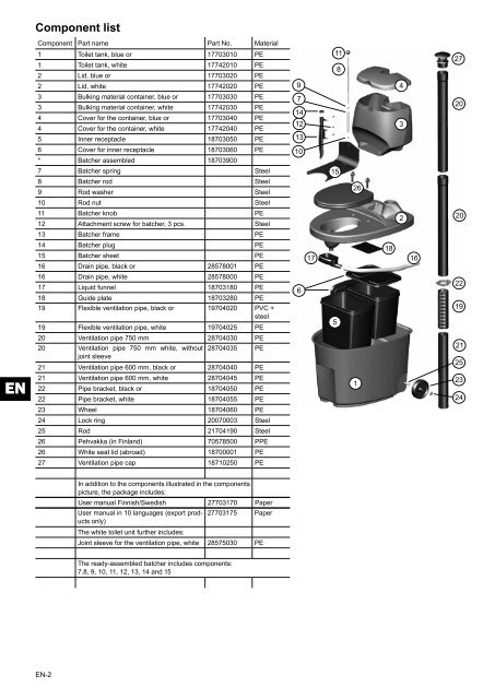
Component listComponent Part name Part No. Material1 Toilet tank, blue or 17703010 PE1 Toilet tank, white 17742010 PE2 Lid, blue or 17703020 PE2 Lid, white 17742020 PE91184273 Bulking material container, blue or 17703030 PE3 Bulking material container, white 17742030 PE4 Cover for the container, blue or 17703040 PE4 Cover for the container, white 17742040 PE5 Inner receptacle 18703050 PE71412133206 Cover for inner receptacle 18703060 PE* Batcher assembled 18703900107 Batcher spring Steel8 Batcher rod Steel9 Rod washer Steel152610 Rod nut Steel11 Batcher knob PE12 Attachment screw for batcher, 3 pcs. Steel22013 Batcher frame PE14 Batcher plug PE15 Batcher sheet PE16 Drain pipe, black or 28578001 PE17181616 Drain pipe, white 28578000 PE17 Liquid funnel 18703180 PE18 Guide plate 18703280 PE19 Flexible ventilation pipe, black or 19704020 PVC +steel19 Flexible ventilation pipe, white 19704025 PE65221920 Ventilation pipe 750 mm 28704030 PE20 Ventilation pipe 750 mm white, without 28704035 PEjoint sleeve21 Ventilation pipe 600 mm, black or 28704040 PE2125EN21 Ventilation pipe 600 mm, white 28704045 PE22 Pipe bracket, black or 18704050 PE22 Pipe bracket, white 18704055 PE1232423 Wheel 18704060 PE24 Lock ring 20070003 Steel25 Rod 21704190 Steel26 Pehvakka (in Finland) 70578500 PPE26 White seat lid (abroad) 18700001 PE27 Ventilation pipe cap 18710250 PEIn addition to the components illustrated in the componentspicture, the package includes:User manual Finnish/Swedish 27703170 PaperUser manual in 10 languages (export productsonly)27703175 PaperThe white toilet unit further includes:Joint sleeve for the ventilation pipe, white 28575030 PEThe ready-assembled batcher includes components:7.8, 9, 10, 11, 12, 13, 14 and 15EN-2
1. Planning and installationWhen selecting a location for, and then installing, the <strong>Biolan</strong> SeparatingDry Toilet, make sure to allow sufficient space for its use andmaintenance, and route the ventilation pipe straight up through theroof above the ridge. Collect the liquid in a closed tank for later use,treat it together with other wastewater from the property, or take it tothe wastewater treatment plant. When dimensioning the liquid tankand deciding where to locate it, you need to take into account thatthe daily amount of liquid from the separating toilet is 1-1,5 litres peruser. The method for post-treating the solid waste should also becarefully planned, to enable easier servicing of the unit.Technical specifications--length 78 cm, width 59.4 cm--sitting height 53 cm--height 85 cm, 98.5 cm to the batcher's knob--weight about 16 kg--inner receptacle 28 l, 2 pcs.--external diameter of the ventilation pipe 75 mm--external diameter of the liquid removal pipe 32 mmInstallation exampleThe picture is indicative only1.1 Placing the Separating Dry Toilet in thetoilet spaceInstall the Separating Dry Toilet at a level position on the floor. Whendeciding where to locate the unit, take into account the space requiredfor its ventilation and liquid removal arrangements, and forits maintenance.1.2 Installing the ventilation pipeRoute the ventilation pipe from the toilet unit straight up over theroof ridge. Any bends in the pipe will impede natural ventilation,causing odour problems. Join up the ventilation pipe as shown inthe detail drawing (page 2), and seal the pipe using a sealant suitablefor the roofing material. As required, extend the ventilation pipewith a Ø 75-mm sewer pipe, or with the pipe parts that are sold asspare parts for the toilet.In complicated installations, or if installing the toilet within livingquarters, it is recommended that the ventilation be ensured usinga separate <strong>Biolan</strong> Exhaust Ventilator or <strong>Biolan</strong> Wind Fan. You canobtain the Exhaust Ventilator either as an option, or retro-fit it if itproves necessary (see Accessories on page EN-6).The flexible ventilation pipe (part 19) is easiest to installwhen warm, using a screwdriver as a stretching aid. Asnecessary, the surfaces can be made slippery using, forexample, dishwashing detergent.EN1.3 Conducting the liquid away after separationRoute the liquid after separation from the toilet unit into either theliquid tank or the sewer system. During installation, provide sufficientgradient to enable the liquid to flow without obstruction all theway to the drain.Depending on the installation location, accomplish the lead-througheither as a sewer or as a pipe leading through the wall or the floor.The diameter of the toilet unit liquid hose is 32 mm. Sewer pipeparts or a hose 32 mm in diameter are suitable for conducting theliquid away. We recommend using a coupling sleeve at the pipe orhose joint.The toilet unit has no drain trap. If the liquid is routed into a tank,the hose must extend all the way to the bottom, in which case thesurface of the liquid in the tank makes a drain trap in the hose. Thusthe air cannot flow from the liquid tank back to the toilet unit. Thetank must be provided with either a pressure relief valve or someother way for the replacement air.If you intend to route the liquid to the sewer system, your plan shouldexplicitly take into account the ventilation of the sewer system andthe toilet space.EN-3