DRAIN MASTER INSTALLATION INSTRUCTIONS
DRAIN MASTER INSTALLATION INSTRUCTIONS
DRAIN MASTER INSTALLATION INSTRUCTIONS
- No tags were found...

Create successful ePaper yourself
Turn your PDF publications into a flip-book with our unique Google optimized e-Paper software.
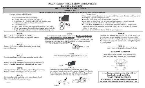
<strong>DRAIN</strong> <strong>MASTER</strong> <strong>INSTALLATION</strong> <strong>INSTRUCTIONS</strong>DM20RP or DM20RPMSPLEASE, BEFORE YOU TRY IT YOUR WAY,TRY IT OUR WAY . . . . . .Our valves install differently than a manual valve, please read the instructions before you begin installation.What you will need to do this install:Special Notes:♦Make sure you have good access to the manual override wherever you choose to install your valve.• Basic mechanical /electrical knowledge ♦Do not place fingers in running area of valve.• 12 VDC power source (to connect the switch to) ♦Installation is simple and can be accomplished in a short time.• Drain Master Kit – DM20RP or DM20RPMS – includes valve, ♦Never install the Drain Master with the motor/gear/gate housing down. Can be installedseal, nuts, bolts, lubricant, switch, and instructions. horizontally or vertically. (See Note with picture below on how to install).• 7/16” wrench/socket ♦PLEASE DO NOT OPERATE Drain Master prior to installation on the RV. The gate has a• 5AMP in line glass type fuse (not supplied) available at auto stores sharp edge and the motor is powerful and very fast. YOU COULD GET HURT. You assume• If you want to mount the switch farther then the valve/switch wire liability for your actions.length allows, you will need connectors and 20 or 18 gauge wire.♦Do not use any other lubricant than the DOW 111 we have provided.STEP 1: STEP 7:STEP 10:EMPTY AND FLUSH HOLDING TANKS!!!Now you are ready to install the new valve. Use the seals that cameInstall the four bolts and hand tighten. Use a 7/16” wrench andThis will make your installation an uneventful success. with your new valve (this is very important). Coat the area of the sealin a criss cross pattern, snug the nuts down ¼ turn at a time.that comes in contact with the gate using the supplied lubricant (Dow 111). Tighten the four bolts evenly, being careful not to over tighten.Place the seals over the flange lip (Flange lip is on existing plumbing).The components are plastic and can crack. The tightening spec*****VERY IMPORTANT STEP*****is 20 inch pounds.STEP 2:Remove the four bolts holding the existing manual dump FLANGESTEP 11:valve to plumbing. Add water to holding tank and check for leaks.STEP 3:Separate plumbing enough to remove existing manual valve.STEP 4:Remove the 2 seals from pipe flanges or from existing manualvalve. **The old seals will not work with your new valve.**STEP 5:Clean pipe flanges, check for cracks, replace flange if necessary.Remove caution card from gate area on new valve.STEP 6:Use manual override to close gate if it is not already closed.This will make the following steps easier.DM28-4STEP 8:With the remaining lube, apply to both sides of gate.SEALSGATESTEP 9:Separate pipe flanges and insert Drain Master making surethe seals are in their correct position, on the flanges. (See Step 7)Rotate the valve to align the four bolt holes with the flange holesand insert the four new bolts and nuts. See pictures below:NOTE: HOW TO INSTALLDrain Master can be installed in any position otherthan in housing down position. See picture below:Drain Master can be installed in any position otherthan in housing down position. See picture below:If you have questions or need help with aninstall, please call us toll freePHASE FOUR INDUSTRIES877-787-8833 or see our Troubleshooting guide onthe web at http://phasefourindustries.com/dm21_2.pdf
SWITCH <strong>INSTALLATION</strong> <strong>INSTRUCTIONS</strong>OPERATING INFORMATIONNOTE: DO NOT HOLD SWITCH DOWN LONGERTHAN 2 SECONDSCongratulations on your purchase of a quality product from PhaseFour Industries.Regular Switch LED SwitchThe switch to operate Drain Master comes wired so that all you need to do is:1. Insert the switch through the black switch plate being sure that the red and white wires on the switch are on top toward open.**Red & white wire must be on top toward open or your valve will operate in the opposite direction.2. Install the switch in a convenient location on your coach, mount with four screws (included).3. You will need to install a 5 AMP in line glass type fuse to protect the motor.-The fuse needs to be in line between the battery positive source and the switch. You may use an existing sparefuse on a fuse block or use an in line type.Note: If you want to mount the switch farther from the Drain Master than the wire length allows, simply add buttconnectors (not included) to the 4 wires and mount the switch in the location you desire. Never use wire smaller than 20 gauge.IMPORTANT: Connect -• Black lead on switch – fused connect to positive 12VDC only• Green lead on switch – connect to negative (ground)• Red wire from switch – connect to red wire on valve• White wire from switch – connect to white wire on valve• If you have the LED switch version, the two labels on the switch that are labeled “To Mag Switch” needto be connected to the two wires on the magnetic switch. See schematic below. You can also visit ourweb site for a larger viewing of this diagram. (www.drainmaster.com)Manual Override Feature***NOTE – Use ¼” flat head screwdriver only on manual override***Your new Drain Master is extremely easy to use but may requiremaintenance. After installation has been completed according tothe installation instructions you are ready to open the DrainMaster for the first time.• Push the switch up toward the word “open” and listen forthe Drain Master to make a sound. The Drain Masterwill open in approx. 1 second which means you do nothave to hold the switch in the open position for more than2 seconds.NOTE: If the valve does not open, check to be sure you have12VDC to the black wire and that the green wire is ground. Oneof these two wires is usually the problem. Check to see that theunit does not open when you push the switch toward the “Close”position. If this happens, your switch is upside down. Be sureyou have not overtightened the four bolts holding the DrainMaster to the couplings and that the seals were installed correctly.***NEW FEATURES***• Please note on the new LED feature – if you have the DM20-RP and wishto upgrade this to the LED version, remember it is much easier to use theupgrade kit before you have the valve installed.• Double sided, manual override –(Make sure you install your valve witheasy access to the manual override). Should you ever lose power to yourRV, you can open or close the valve manually. To do this you will need a¼” standard slot screw driver. On either side of the Drain Master, youwill see the words Manual Override on the upper center area. The wordsOpen and Close with directional arrows provide directions in which youturn the slotted shaft in the middle of this wording. Turn in the directionyou need. There will be resistance as you are overriding a safety clutch.Turn until the shaft stops. When convenient, check and correct electricalproblems.• NOTE: Unless you have specifically ordered a weatherproof switch foryour valve, the switch is not weatherproof, and should be mounted in anarea protected from moisture. Weatherproof switch is available forpurchase.