LDD High Power CW Laser Diode Drivers
LDD High Power CW Laser Diode Drivers
LDD High Power CW Laser Diode Drivers
- No tags were found...

Create successful ePaper yourself
Turn your PDF publications into a flip-book with our unique Google optimized e-Paper software.
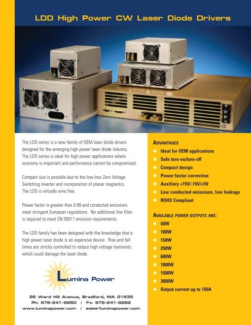
<strong>LDD</strong> <strong>High</strong> <strong>Power</strong> <strong>CW</strong> <strong>Laser</strong> <strong>Diode</strong> <strong>Drivers</strong>The <strong>LDD</strong> series is a new family of OEM laser diode driversdesigned for the emerging high power laser diode industry.The <strong>LDD</strong> series is ideal for high power applications whereeconomy is important and performance cannot be compromised.Compact size is possible due to the low-loss Zero VoltageSwitching inverter and incorporation of planar magnetics.The <strong>LDD</strong> is virtually wire free.<strong>Power</strong> factor is greater than 0.99 and conducted emissionsmeet stringent European regulations. No additional line filteris required to meet EN 55011 emission requirements.The <strong>LDD</strong> family has been designed with the knowledge that ahigh power laser diode is an expensive device. Rise and falltimes are strictly controlled to reduce high voltage transientswhich could damage the laser diode.26 Ward Hill Avenue, Bradford, MA 01835Ph: 978-241-8260 / Fx: 978-241-8262www.luminapower.com / sales@luminapower.comADVANTAGES◆ Ideal for OEM applications◆ Safe turn-on/turn-off◆ Compact design◆ <strong>Power</strong> factor correction◆ Auxiliary +15V/-15V/+5V◆ Low conducted emissions, low leakage◆ ROHS CompliantAVAILABLE POWER OUTPUTS ARE:◆ 50W◆ 100W◆ 150W◆ 250W◆ 600W◆ 1000W◆ 1500W◆ 3000W◆ Output current up to 150A
<strong>LDD</strong> <strong>CW</strong> <strong>Laser</strong> <strong>Diode</strong> Driver SpecificationsModel Pout max Iout max Input Voltage Size (L x W x H)<strong>LDD</strong>-50-XX-YY 50W Up to 15A 90-264VAC<strong>LDD</strong>-100-XX-YY 100W 5A to 50A 90-264VAC<strong>LDD</strong>-150-XX-YY 150W 10A to 60A 90-264VAC<strong>LDD</strong>-250-XX-YY 250W 10A to 80A 90-264VAC<strong>LDD</strong>-600-XX-YY 600W 90-264VAC<strong>LDD</strong>-1000-XX-YY 1000W 10A to 100A90-264VAC<strong>LDD</strong>-1500-XX-YY* 1500W 180-264VAC<strong>LDD</strong>-3000-XX-YY* 3000W Up to 150A 180-264VACAuxiliary Outputs +5V @0.5A**+15V @0.5A**-15V @0.5A****(no auxiliary outputs available on <strong>LDD</strong>-50.)XX = Maximum rated output current YY = Maximum compliance voltageXX*YY cannot exceed Pout max*<strong>LDD</strong>-1500 and <strong>LDD</strong>-3000 require AC input voltage between 180-264VACRS-232 Option availableOther outputs available upon requestINPUTVoltage:See table above<strong>Power</strong> Factor: >.986.75” x 3.63” x 3.25”17.1 x 9.2 x 8.26 cm7.5” x 5.8 x 2.6”19 x 14.7 x 6.6 cm9.9” x 7.3” x 2.6”25.1 x 18.5 x 6.6 cm17” x 16.6” x 3.4”43.2 x 42.2 x 8.6 cmINTERFACEConnector:Current Program:Current Monitor:Voltage Monitor:PERFORMANCERise/Fall Time:Current Regulation:Current Ripple:Current Overshoot:<strong>Power</strong> Limit:ENVIRONMENTOperating Temp:Storage:Humidity:Cooling:REGULATORYSafety:Emissions/Immunity:15 Pin “D” Sub Female0-10V for 0-Max Current0-10V for 0-Max Current0-10V for 0-Max Voltage
<strong>LDD</strong> InterfaceCONNECTOR TYPE: 15 PIN D-SUB FEMALE(Refer to Figure 2, <strong>LDD</strong> Interface Schematic)Pin # Pin Name Functional Voltage Level Description1 Enable <strong>High</strong> = RUN = +5V to +15V(input)Low = OFF = 0V3 Interlock Open = OFF(input)Connect to GND = RUN4 GND5 *Vout Monitor: 0-10V = 0-Vout max(output)6 Iout Monitor 0-10V = 0-Iout max(output)7 Iprogram(+): 0-10V = 0-Iout max(input)8 Pulse Control TTL <strong>High</strong> = On(input)TTL Low = OFF(<strong>LDD</strong>-3000 only) Default = On(<strong>LDD</strong>-3000 only)9 GND10,11 +5V @ 0.5A(output)12 -15V @0.5A(output)13,14 +15V @0.5A(output)15 GNDThe Enable function turns the output section ofthe power supply ON and OFF. When the powersupply is enabled, current is delivered to load asprogrammed via Iprogram(+), Pin 7. Rise timesresulting from Enable are approximately 25msec.The Interlock function can be connected to externalinterlock switches such as door or overtempswitches.Interface return.The output voltage of the supply can be monitoredby Vout Monitor. See note belowThe output current of the supply can be monitoredby Iout Monitor.The power supply output current is set by applyinga 0-10V analog signal to Iprogram(+).The output of the <strong>LDD</strong>-3000 may be pulsed byapplying a TTL signal to Pulse Control, pin 8. Theamplitude of the output current pulse is determinedby the current level programmed via Pin 7,Iprogram(+). Rise fall times of
<strong>LDD</strong> Outline Drawings26 Ward Hill AvenueBradford, MA 01835Ph: 978-241-8260Fx: 978-241-8262www.luminapower.comsales@luminapower.com