Brake Motors Brake Motors - SAT Antriebstechnik GmbH & Co KG
Brake Motors Brake Motors - SAT Antriebstechnik GmbH & Co KG
Brake Motors Brake Motors - SAT Antriebstechnik GmbH & Co KG

Create successful ePaper yourself
Turn your PDF publications into a flip-book with our unique Google optimized e-Paper software.
<strong>Brake</strong><strong>Motors</strong>General catalogue
<strong>Brake</strong>motorsISO 9001: 2000Certified Quality System
IndexBA series General Characteristics2GENERAL INFORMATIONPRODUCT RANGE: POWER AND POLESMOTOR DESIGNATIONSTANDARDS AND APPROVALSCE MARKCSA APPROVAL AND UL STANDARDSCCC CERTIFICATIONGOST-R CERTIFICATIONMOTOR IDENTIFICATION NAMEPLATETOLERANCESSTANDARD AND SPECIAL FLANGESTYPE OF COSTRUCTIONS AND MOUNTING ARRANGEMENTSENCLOSURE RATINGSBEARINGSRECTIFIERSVOLTAGE AND FREQUENCY SUPPLYOPERATING AT 60 HZDUTY TYPESMOTOR RUNNING ON INVERTERBALANCINGNOISETEMPERATURE, ALTITUDE, HUMIDITYPROTECTION DEVICESBA SERIES GENERAL CHARACTERISTICSBA SERIES BRAKE GROUPAIR GAP ADJUSTMENTBRAKE TORQUE ADJUSTMENTPERMISSIBLE STARTING FREQUNCY WITH LOADBRAKE COIL WIRING CONNECTIONBRAKE TORQUE AND BRAKE SPRINGS COMPRESSIONTECHNICAL DATA SINGLE SPEED MOTORS - SINGLE WINDING,(2, 4 POLES)TECHNICAL DATA SINGLE SPEED MOTORS - SINGLE WINDING,(6, 8 POLES)TECHNICAL DATA TWO SPEED MOTORS - SINGLE WINDING,(2 / 4 POLES)TECHNICAL DATA TWO SPEED MOTORS - SINGLE WINDING,(4 / 8 POLES)TECHNICAL DATA TWO SPEED MOTORS - TWO WINDINGS,(2 / 6 POLES)TECHNICAL DATA TWO SPEED MOTORS - TWO WINDINGS,(2 / 8 POLES)TECHNICAL DATA TWO SPEED MOTORS - TWO WINDINGS,(4 / 6 POLES)TECHNICAL DATA TWO SPEED MOTORS - TWO WINDINGS,(4 / 12 POLES)45677777899101112131414151617171819212222222222232425262728293031
Index3232333334373838383939404142434445TECHNICAL DATA TWO SPEED TWO WINDINGS MOTORS,(2 / 12 POLES)HOISTING MOTORS 4 / 16 POLESBRAKE LININGS WEARSTARTING AND BRAKING TIMEBA SERIES DIMENSIONSBM SERIES GENERAL CHARACTERISTICSBM BRAKE GROUPAIR GAP ADJUSTMENTPERMISSIBLE STARTING FREQUENCY WITH LOADBRAKE REACTION TIME AND RECTIFIER WIRING DIAGRAMSBRAKING TIME CALCULATIONTECHNICAL DATA SINGLE SPEED MOTORS - SINGLE WINDING(2, 4 POLES)TECHNICAL DATA SINGLE SPEED MOTORS - SINGLE WINDING(6, 8 POLES)TECHNICAL DATA TWO SPEED MOTORS - SINGLE WINDING(2 / 4, 4 / 8 POLES)TECHINICAL DATA TWO SPEED MOTORS - TWO WINDINGS(2 / 6, 2 / 8 POLES)TECHNICAL DATA TWO SPEED MOTORS - TWO WINDINGS(4 / 6, 4 / 12 POLES)BM SERIES DIMENSIONSBA seriesBM series4648484950515253545556575757575858596062TRAVERSE MOTORSWITH PROGRESSIVE START AND STOP (PV SERIES)HOISTING MOTORS (BAPK SERIES)PREMIUM BRAKE TORQUE (BAF SERIES)FORCED COOLING MOTORS (SV SERIES)BUILT-IN ENCODER MOTORS (E SERIES)BAE SERIES DIMENSIONSBMEAV SERIES DIMENSIONBUILT-IN INVERTER MOTORSBUILT-IN INVERTER MOTORS SPECIFICATIONSDOUBLE BRAKE MOTORS (BMBM SERIES)BMBM SERIES DIMENSIONSMOTORS FOR USA AND CANADAMOTORS FOR AUSTRALIA AND NEW ZEALANDMOTORS FOR CHINAMOTORS FO RUSSIAPACKAGINGTERMS AND CONDITIONS OF SALE AND WARRANTYSPECIAL FEATURES AND OPTIONSSPARE PARTS BA SERIESSPARE PARTS BM SERIES3
GENERAL INFORMATIONGENERAL CHARACTERISTICSMGM brake motors are asynchronousthree-phase totally enclosed fan cooledmotors (TEFC). The motor brakes in caseof power supply failure. The braking actionis always obtained through a very quickand precise stop and it guarantees a safeand prompt intervention in case of anunintentional power supply failure.The braking action is obtained withoutshaft axial sliding and it provides equalbraking torque in both directions of rotation.MGM brake motors are particularlysuitable for hoisting and traverse machines,tooling machinery, automatic andtransfer machinery in textile, ceramicand packing fields and in all those situationwhere precision and quickness inbraking are required.MGM brake motors are designed andassembled as real brake motors. Theperfect engineering and assembling combinedwith a strong and safe brake, makethese motors very reliable.As standard, on the IM B3 mounting (footmounted), feet are integrated in the frame(they are not attached to the frame)making the motor very sturdy. This featureis very important on those brake motorapplications where the stress duringstart/stop is very high.The brake disc lining material is asbestosfree with high friction coefficient and verylong lasting.The motors are provided with IP 54 enclosurerating and insulation class F.On request they can be provided with IP55 or IP 56 enclosure ratings and withclass H insulation .All MGM motors are designed for inverterduty. On request it is possible to supplythe motor with the encoder fitted on thesecond shaft end or to have the secondshaft end ready to fit an encoder. Forfurther information please refer to theencoder series section.MGM brake motors series are: BA andBM.BA seriesThe BA series consists of three phase, asynchronous brake motors totally enclosed fan cooled (TEFC). The BA series range startsfrom 71 up to 280 frame size. As standard, the brake power supply is AC 3-phase. On request DC brake can be provided with arectifier integrated in the terminal box. The rectifier is provided with an over-voltage and radio frequency emission protectiondevice. All BA series motors are provided with manual brake release. The BA series cooling fan is fitted between the motor andthe braking assembly. The brake moving element and the brake coil have a laminated magnetic nucleus to reduce losses and toallow very fast braking. BA series main features are a very quick braking action, both in unlocked and high torque braking, aconstant braking time and a very high number of start/stop cycles also under severe applications.BM seriesThe BM series consists of three phase, asynchronous brake motors totally enclosed fan cooled (TEFC). The BM series range startsfrom 56 up to 160 frame size. As standard the brake power supply is DC with a rectifier integrated in the terminal box. The rectifieris provided with an over-voltage and radio frequency emission protection device. The cooling fan is fitted at non-drive shaft end.BM series main features are low braking noise, gradual acceleration during the motor start and stop and the reduced overalldimensions.The BA and BM series are also available in the following main versions:PV (BAPV, BMPV): with flywheel that allow progressive start and stop, particularly suitable for traverse application.F (BAF): with double brake disc and extremely high brake torque.AV-SV with forced cooling (BMAV with axial forced cooling, BASV with double radial forced cooling)4
Product rangeThe table below shows the brake motors production range of BM, BA motor series.MotorType56 A56 B63 A63 B63 C63 D71 A71 B71 C71 D80 A80 B80 C90 SA90 SB90 LA90 LB90 LC100 LA100 LB112 MB112 MC132 SA132 SB132 MA132 MB132 MBX160 MA160 MB160 LA160 LB180 LA180 LB200 LA200 LB225 S225 M225 MX250 M280 S280 MSeriesBMBMBMBMBMBMBM BABM BABM BABM BABM BABM BABM BABM BABM BABM BABM BABM BABM BABM BABM BABM BABM BABM BABM BABM BABM BABM BABM BABM BABM BABABABABABABABABABABA2 polekW0.090.120.180.250.370.450.370.550.750.751.11.52.23.04.05.55.57.59.211.011.015.018.522.030.037.04 polekW0.060.090.120.180.220.300.250.370.550.650.550.750.901.101.501.852.22.23.04.05.55.57.59.211.09.211.015.018.522.030.037.045.055.075.090.06 polekW0.040.060.090.120.180.250.370.550.751.101.301.501.852.23.04.05.57.59.211.015.018.522.030.037.037.045.055.08 polekW0.070.080.110.180.250.370.550.650.751.11.52.23.04.05.57.511.015.022.030.037.045.02 / 4 polekW0.22/0.150.26/0.170.25/0.180.37/0.250.65/0.450.88/0.621.3/0.91.8/1.22.2/1.52.2/1.53.1/2.34.5/3.35.0/4.56.0/5.07.5/6.09.5/8.011.0/9.013.0/11.017.0/14.020.5/17.024.0/20.037.0/30.045.0/35.04 / 8 polekW0.13/0.070.18/0.090.22/0.120.25/0.180.37/0.250.75/0.371.1/0.61.6/0.92.2/1.23.0/2.04.0/2.76.0/4.06.5/4.59.5/6.011.0/8.014.0/9.018.0/11.021.0/13.030.0/18.035.0/25.042.0/30.045.0/33.055.0/40.02 / 6 polekW0.25/0.080.35/0.10.37/0.120.55/0.180.9/0.31.2/0.41.4/0.51.6/0.62.2/0.83.0/1.04.0/1.35.5/1.87.0/2.28.0/2.511.0/3.616.0/6.52 / 8 polekW0.18/0.040.25/0.060.35/0.070.37/0.090.55/0.120.75/0.181.1/0.251.3/0.31.6/0.42.2/0.53.0/0.84.0/1.15.5/1.57.0/1.88.0/2.211.0/3.016.0/4.018.5/4.524.0/6.030.0/7.54 / 6 polekW0.18/0.110.25/0.180.37/0.250.55/0.370.75/0.551.1/0.81.5/1.02.0/1.32.2/1.53.0/2.23.7/2.55.5/3.77.5/5.011.0/7.513.0/8.815.0/10.54 / 12 pole kWS3 40%0.25/0.050.37/0.070.4/0.130.55/0.180.75/0.220.9/0.251.1/0.351.5/0.452.5/0.83.0/1.04.0/1.34.8/1.67.3/2.42 / 12 pole kWS3 40%0.45/0.070.75/0.111.1/0.151.85/0.253.0/0.454.0/0.655.5/0.97.0/1.18.0/1.3**11.0/1.8**16.0/2.64 / 16 pole kWS4 40% - 4 poleS4 25% - 16 pole2.8/0.74.0/1.15.5/1.3**7.3/1.8**10.0/2.5**13.2/3.016.0/4.019.0/4.824.0/6.030.0/7.540.0/10.050.0/12.5GENERAL CHARACTERISTICS** Powers available for BA series onlyNote: All the above motors can be provided in the standard execution, without the brake also with a servo fan, built-in encoder or builtininverter.5
Motor DesignationGENERAL CHARACTERISTICSThe following technical characteristics are used to correctly identify MGM motors:SeriesFrame sizePower and polesMountingVoltage and frequencyBM, BA156 - 280 mm0.04 - 90 kW2 4 6 8 2 - 4 4 - 8 2 - 62 - 8 4 - 6 4 - 12 poles 2See mounting sectionAccording to customer requestexample: BAexample: 71example: 0.37 kW 4 polesor B 4 (see technical data)example: IM B5example: 230/400V 50 Hz<strong>Brake</strong> supplyInsulation classEnclosureAC or DC 3Single or double terminal board box 4F or HIP54, IP55, IP563example: AC brake coil, doubleterminal board box for separatebrake supplyexample: class Fexample: IP 54It is necessary to indicate any special features or options not supplied as standard (see page 59), such as reduced diameterflanges, thermal protectors, tropical environment execution, etc. Unless otherwise specified, the brake supply voltage is thesame as the motor voltage. Unless otherwise specified, the DC brake voltage supply is 230V 50/60 Hz.1The BM, BA series are also available in the versions BMPV, BAPV with soft start and stop suitable for traversing, and the versionBMSV, BASV with forced cooling fan. The BA series is also available in the version BAF, with double brake disc and premium braketorque.2In two speed motors, the model number is followed by the letter D on motors with Dahlander winding, and by the letters DA onmotors incorporating two separate windings (i.e. BADA 71 B 2/8).3BA series motors are available with both DC and AC brakes while BM series motors are available with DC brakes only. DC brakemotors with power supply higher than 24 Volts have as standard a rectifier with emission suppression.4Single speed motors can be provided with a single terminal board box with the motor and brake power terminals connected inparallel, or with a double terminal board, having the motor supplied separately from the brake. Unless otherwise specified, singlespeed motors up to 112 frame size are provided with just one terminal board. <strong>Motors</strong> with frame size 132 and above are providedas standard feature with a double terminal board box. On two speed motors, the motor power supply is always separate fromthe brake power supply. On single speed motors with separate brake power supply a double terminal board box has to be provided.A double terminal board box also has to be provided on motors with the following options or auxiliary devices: thermo protectors,thermistors (PTC), standstill heaters, forced cooling, IP 56 enclosure, EMI filters, DC brake with brake power supply higher than254V, brake voltage different from motor voltage, motor voltage 400/690V 50Hz, encoder, microswitch, side terminal box.ExampleBA 71 B4, 230/400V 50 Hz, class F, IP 54, IM B5, AC brake coil, double terminal board box.6
Standards and approvalsDescription IEC CENELECRatings and performance IEC 60034 - 1EN 60034 - 1Standard methods for determining losses andefficiency using tests<strong>Co</strong>oling methods for rotatingelectrical machinesTerminal markings and direction ofrotation of rotating machinesIEC 60034 - 2 - 1IEC 60034 - 6IEC 60034 - 8EN 60034 - 2 - 1EN 60034 - 6EN 60034 - 8GENERAL CHARACTERISTICSCharacteristics of mountingsand types of installationIEC 60034 - 7EN 60034 - 7Starting performance of asynchronous three phasesingle speed cage motorsIEC 60034 - 12EN 60034 - 12Classification of protection degree ofrotating electrical machinesIEC 60034 - 5EN 60034 - 5Mechanical vibrations of machines with shaft height56 mm and higher. Measurement, assessment andlimits of vibration severityFixing dimensions and rating powersIEC 60034 - 14IEC 60072EN 60034 - 14EN 50347Noise limitsIEC 60034 - 9EN 60034 - 9MarkMGM brake motors have the mark on the nameplate to indicate the conformity to the requirements of 2006/95/CE “Low VoltageDirective” and 2004/108/CE “Electromagnetic <strong>Co</strong>mpatibility Directive”.CSA approval and UL standardsOn request MGM motors can be provided with cCSAus approval in conformity with the requirements of UL 1004 “Electric motors” andCSA C 22.2 No. 100 “<strong>Motors</strong> and generators” for the North American market. The approved motors show the mark on the nameplate.CCC approvalOn request MGM motors can be provided with CCC (China <strong>Co</strong>mpulsory Certification) approval for the Chinese market. The approvedmotors show the mark on the nameplate.On request MGM motors can be provided with GOST-R approval for the russian market.GOST-R approval7
Motor identification nameplateGENERAL CHARACTERISTICSEvery motor is provided with an identifying nameplate, on which specific motor information is given. Motor nameplates areshown below with motor data and explanatory notes. The nameplate shown on the left is used for single speed motors whilethe nameplate on the right is used for two speed motors.516282 3 47 9 82910 11 12 13 14171819202115223216233031516282 3 47 9 82924 25262728 1028 17321118121932321 Duty type2 Protection degree3 Insulation Class, the letters TR following the insulation class means tropicalized treatment4 Weight (Kg)5 Motor type Designation6 Serial Number7 Maximum Static <strong>Brake</strong> Torque obtainable with proper regulation of the springs (Nm)8 <strong>Brake</strong> current (A).9 <strong>Brake</strong> Voltage Supply (V). On brake motors with AC brake, the symbol “Vb = Vm” indicates that the motor and brake have the samevoltage supply.10 Rated Power (kW) at 50 Hz11 Power Factor at 50 Hz12 Motor Speed (RPM) at 50 Hz13 Motor Voltage Supply at 50 Hz, Delta connected14 Motor Amps at 50 Hz, Delta connected15 Motor Voltage Supply at 50 Hz, Star connected16 Motor Amps at 50 Hz, Star connected17 Rated Power (kW) at 60 Hz18 Power Factor at 60 Hz19 Motor Speed (RPM) at 60 Hz20 Motor Voltage Supply at 60 Hz, Delta connected21 Motor Amps at 60 Hz, Delta connected22 Motor Voltage Supply at 60 Hz, Star connected23 Motor Amps at 60 Hz, Star connected24 Motor voltage supply at 50 Hz25 Motor Amps at 50 Hz26 Motor voltage supply at 60 Hz27 Motor Amps at 60 Hz28 Mounting29 For motors with additional cooling fans, the fan voltage supply is shown in this location, preceded by the letters “VENT”. The letters“TP” indicate the presence of bimetallic thermal protectors, “TM” indicate thermistors, and “SCALD” indicates anti-condensation heaters,all followed by the voltage supply.30 Efficiency and efficiency class at 50Hz31 Efficiency and efficiency class at 60Hz32 Certification marks ( , , etc.)8
TolerancesElectromechanical CharacteristicsThe table below, describes the electromechanical tolerances concerning electric motors, according to the EN 60034-1 standard.ParameterEfficiencyPower FactorLocked Rotor CurrentMoment of InertiaLocked Rotor TorquecosϕTolerance– 0.15 (1 - η) Rated power ≤150 kW– (1 - cos ϕ) / 6 min 0,02 - max 0,07Slip ±30% Rated power
Type of construction and mountingGENERAL CHARACTERISTICSThe table below shows the most important types of mounting arrangements according to IEC 34-7(EN 60034-7) standard. Two systems of classification are provided: code 1 (the alpha-numeric designation) and code 2 (the allnumeric designation).Horizontal shaft MountingsIM B3 IM 1001 IM B5 IM 3001 IM B35 IM 2001IM B6 IM 1051Foot mounted motor, feet down. Flange mounted on D-End side. Foot and flange mounted motor. Foot mounted motor. Feet left (viewedfrom D-End)IM B7 IM 1061IM B8 IM 1071 IM B14 IM 3601 IM B34 IM 2101Foot mounted motor. Feet right(viewed from D-End)Foot mounted motor. Feet up(viewed from D-End)Face mounted. Flange with threadedholes and spigotFace and foot mounted. Flangewith threaded holes and spigot.Vertical shaft MountingsIM V1 IM 3011 IM V15 IM 2011 IM V3 IM 3031 IM V36 IM 2031Flange mounted. Shaft down.Foot and flange mounted motor.Shaft down.Flange mounted. Shaft up.Foot and flange mounted motor.Shaft up.IM V5 IM 1011 IM V6 IM 1031 IM V18 IM 3611 IM V19 IM 3631Foot mount. Shaft down. Foot mount. Shaft up. Face mount. Shaft down. Flange Face mount. Shaft up. Flange withwith threaded holes and spigot. threaded holes and spigot.Notesfor information about the classifications of other types of construction and mounting please contact MGM.10
Enclosure Rating (Protection Degree)The enclosure rating of the motor has to be suitable to the environment conditions the motor operates in. According to theIEC34-5 (EN 60034-5) standard the designation of the protection degree is expressed by means of a symbol made up of twoletters (IP) followed by a two digit number. The first digit indicates the protection degree provided by the motor enclosure incontact with parts in motion, electrically energized, or against the penetration of foreign bodies. The second digit indicatesthe protection degree of the motor enclosure against damages caused by the penetration of liquids.First digit0 No protection.1 The machine is protected against the penetration of solidbodies greater than 50 mm in diameter (for example, protectionagainst the accidental touch of a hand).2 The machine is protected against the penetration ofsolidbodies greater than 12 mm in diameter.3 The machine is protected against the penetration of solidbodies greater than 2.5 mm in diameter.4 The machine is protected against the penetration of solidbodies greater than 1mm in diameter.5 The machine is protected against the penetration of dust.The penetration is not completely avoided, but should notcompromise the good functioning of the machine.6 Dust tight machineIP................... First digit .......................Second digitSecond digit0 No protection.1 Vertical dropping of water on the machine will not result indamaging effects.2 Vertical dropping of water on the machine will not result indamaging effects when the machine is not inclined more than15° from its normal position.3 Water or rain dropping on the machine at an angle up to60° will not result in damaging effects.4 Water spraying on the machine from any angle will notresult in damaging effects to the machine.5 Water jets on the machine from any angle will not result indamaging effects to the machine.6 Waves of water will not result in damaging effects to themachine.7 Immersing the machine in water under specific conditionsof pressure and time will not cause the ingress of a damagingquantity of water.8 Immersing the machine permanently in water underconditions of pressure and time given by the manufacturer willnot result in damaging effects.GENERAL CHARACTERISTICSMGM brake motors come with standard IP54 enclosure rating. On request, motors can be provided with IP55 or IP56 enclosurerating. For use in standard industrial environments IP54 is sufficient. For outdoor applications or for application that involve contactwith water, protection degree IP55 or IP56 is advisable. It’s always advisable to protect the motor as much as possible.During the installation stage secure the proper tightening of the cable gland and the insertion of the wire from the bottom upwards.On request, for outdoor vertical mounting with shaft down, a rain roof (BM series) or a special brake cover (BA series) are availableMGM motors are also available with special corrosion protection for hard environment application such as marine applicationand tough processing applications in poultry, meat, dairy, snack foods and pharmaceuticals. On request motors can be providedwith the following option:• Bearings for high/low temperatures• Oil seal on drive shaft end• Special frame/plates corrosion-resistant surface treatment and/or epoxy painting• Drain holes• Stainless steel nameplate• Stainless steel shaft-end• Stainless steel or zinc plated brake friction surface• Stainless steel nuts, bolts, tie rods and screws<strong>Co</strong>ntact MGM for additional information.11
BearingsGENERAL CHARACTERISTICSAll M.G.M. brake motors are equipped with double seal ball bearings. The bearings are lubricated for life, washers are madeof synthetic rubber very resistant to oil and to wear.Frame Size5663718090100112132160180200225250280Drive End (D)6201 - 2RZ6202 - 2RS16203 - 2RS16204 - 2RS16205 - 2RS16206 - 2RS16306 - 2RS16308 - 2RS16309 - 2RS16310 - 2RS16312 - 2RS16313 - 2RS16316 - 2RS16316 - 2RS1Bearing TypeNon-Drive End (ND)6201 - 2RZ6202 - 2RS16203 - 2RS16204 - 2RS16205 - 2RS16206 - 2RS16306 - 2RS16308 - 2RS16309 - 2RS16310 - 2RS16310 - 2RS16312 - 2RS16314 - 2RS16314 - 2RS1FThe nominal bearings lifetime is expressed in working hours according to the international bearingslifetime calculations, and it depends on the applied load, temperature and speed. The maximum allowedoverhung load (N) acting at the middle of the output shaft (F in the sketch), for the different lifetimesat different speeds, can be obtained from the table below for every motor frame size.FrameSize2 pole20000 Hours4 pole 6 pole 8 pole2 pole40000 Hours4 pole 6 pole 8 pole5663718090100112132160180200225250280320410500660720100014502150270032504300516082508250410520630840900125018502700340041005450654010390103904706007209501000140021003100390047006250745012400124005206508001200130018002650395049005980685082001310013100260330400500550790115017002100260034004000633063303204105006607201000145021502700325043005050795079503704705707508201100165024503050375049505850953095304105206308409001250185027003400410054506400104001040012
RECTIFIERS<strong>Motors</strong> with a DC brake are provided as standard with a rectifier located inside the terminal box. Rectifiers are fitted withan over-voltage and radio frequency emission protection. The diagrams below show different types of rectifiers availableon MGM motors. The M type rectifier is also suitable to be mounted inside an electric panel. All MGM rectifiers can beconnect with two wiring diagrams according to brake intervention time needed (see pages 22 and 39).WhiteWhiteBlackRedType C110WhiteWhiteBlackRedType C230GENERAL CHARACTERISTICSBrown - BlueBrown - GreyRESIN COULOR: GreenINPUT: 110V ~ OUTPUT: 103V =RESIN COULOR: BlueINPUT: 230V ~ OUTPUT: 103V =Type Q110 Type Q230 Type Q400WhiteWhiteBlackRedBrown - GreyWhiteWhiteBlackRedBrown - GreyWhiteWhiteBlackRedBrown - BlueRESIN COULOR: GreenINPUT: 110V ~ OUTPUT: 103V =RESIN COULOR: BlueINPUT: 230V ~ OUTPUT: 103V =RESIN COULOR: YellowINPUT: 400V ~ OUTPUT: 180V =Type M110 Type M230 Type M400RRRRESIN COULOR: GreenINPUT: 110V ~ OUTPUT: 103V =RESIN COULOR: BlueINPUT: 230V ~ OUTPUT: 103V =RESIN COULOR: YellowINPUT: 400V ~ OUTPUT: 180V =13
Motor Voltage and Frequency SupplyGENERAL CHARACTERISTICSMGM motors are provided with a standard voltage rating of 230/400V±10% 50 Hz (IEC 38, CENELEC HD 472, CEI 8-6)“European voltage”. On request they can be provided with different operating voltages.The operating voltages at 50Hz and 60Hz are clearly indicated on the motor nameplate (see motor nameplate section). MGMmotors are suitable to work within a voltage variation of 10% on the nameplate voltage. The available rated voltages are shownin the table below under “Nameplate voltage” at 50 Hz and 60 Hz, while the corresponding voltages on which the motor isable to run are shown under “Usable voltage”.230 / 400 50190 / 330 50208 / 360 50400 / 690 50Nameplate voltage277 / 480 60220 / 380 60254 / 440 60480 / 830 60Usable voltage240 / 415 50 220 / 380 50 265 / 460 60208 / 360 60 230 / 400 60200 / 346 50 240 / 415 60380 / 660 50 415 / 717 50It’s important to understand the torque vs. RPM curvesfor different voltages supplied to the motor (on the side)particularly for those motors running under heavy duty. Ifyou are supplying the brake with a lower voltage than thenominal one, the air gap has to be adjusted more frequentlythan in the case of nominal voltage supply in order toguarantee a constant high brake performance.1201101009080706050403020100Torque %440 V400 V360 V0 10 20 30 40 50 60 70 80 90RPM %100Operating at 60HzMGM motors with rated voltage of 230/400V 50Hz maintain the same rated and starting torque if operating at 277/480V 60 Hz while theRPM increase by about 20% (see torque vs. RPM comparing curves 1 and 2 here below).The AC brake coil on BA series works equally well if operating either at 230/400V 50Hz or at 277/480V 60Hz. The DC brake coil withnameplate voltage of 110V, 230V or 400V on BM and BA series has to be supplied at 110V, 230V or 400V single phase respectively bothat 50 Hz or 60 Hz (i.e. a 230V brake can be supplied single-phase at 230V 50Hz or at 230V 60 Hz).MGM is able to provide motors and brake coil suitable for operating on 220/380V 60Hz power supply. It is not advisable to run motorsdesigned for 230/400V 50Hz and 277/480V 60Hz on 220/380V 60Hz voltage supply as the power remains the same, but the startingtorque is reduced by 35% (see curves 1 and 3 here below).MGM strongly recommends not to use a 277/480V 60Hz (230/400V 50Hz) AC brake coil on 220/380V 60Hz power system as it resultsin a significant loss of performance.DC brakes with a rated voltage of 230V 50Hz can be used on 220V 60Hz and those with a rated voltage of 400V 50Hz on 380V 60Hzpower system.The diagram below shows different curves (torque vs. RPM) for a 230/400V 50Hz (277/480 60Hz) rated voltage motor running on differentpower systems.12230/400V 50Hz (277/480V 60Hz) rated voltagemotor running on 230/400V 50 Hz power system.230/400V 50Hz (277/480V 60Hz) rated voltagemotor running on 277/480V 60 Hz power system.Torque %100%65%1 233230/400V 50Hz (277/480V 60Hz) rated voltagemotor running on 220/380V 60Hz power system.100% 120% RPM %It’s important to point out that, if running the motor at 60Hz instead of 50 Hz, the maximum number of starts reduces by about 15-20%, andthe noise level increases by about 3dB due to the increased speed of the cooling fan.14
Service Duty TypesThe most common duty types are described in this paragraph and a method to calculate the permissible power rise-up isgiven. Please contact MGM for different types of duty.The motor operates with constant loadfor a period of time sufficient to achievethe thermal equilibrium.PowertsTemperature<strong>Co</strong>ntinuous duty S1Limited length duty S2GENERAL CHARACTERISTICSThe motor operates with constant loadfor a limited period of time not sufficientto achieve a thermal equilibrium. Theremaining period of the cycle is a restperiod, during which the motor coolsdown to the ambient temperature again.PowertsTemperaturePeriodic intermittent duty S3The motors follows a cycle including anoperation period with constant load (ts)and a rest period (tr). The synthetic indicationof the duty is given by the intermittentpercentage ratio related to aperiod of time, which usually is 60 min.(f.e. 15% - 60 min.).PowertstctrTemperatureIntermittence ratio =tsts + tr •100%A motor designed for S1 duty but running on S2 or S3 duty can provide a power output higher than the rated one on S1 duty.However, the starting torque remains the same on all duties.The permissible approximate output power for single speed motors can be calculated as follows:Where K is a coefficient given by the following diagrams:Power (S2 or S3 duty cycle)=K•Nominal power1,4KS21,4KS31,31,31,21,21,11,11,0010 30 60 60 75Time (min)1,0010 20 30 40 50 60 70 80 90 100Duty %15
MGM motor running on Inverter Duty (Frequency <strong>Co</strong>nverter).GENERAL CHARACTERISTICSAll MGM motors are designed to be suitable for inverter duty. See below to understand the motor operating under invertercontrol:The motor speed depends on the power supply frequency. Basically the inverter works converting the power input from the linewith a fixed amplitude and frequency into a voltage supply with a variable amplitude and frequency suitable to control the motorspeed. Inverter can’t generate an output voltage higher than the input voltage while it can increase the frequency above theinput rated value; <strong>Co</strong>nstant torque regulation range means a range where the inverter is able to keep the nominal ratio of voltageto frequency constant; in our diagram this range is up to 50 Hz.<strong>Co</strong>nstant power (or flow) regulation range means a range where the inverter can increase frequency (and so the motor rotationspeed), without voltage increase to the motor (and consequentlythe torque); in our diagram this range exceeds 50 Hz;Operating diagram shows the percent values of the torqueavailable both in continuous and overloading running; Whenthe motor is running within constant torque regulation range(frequency below 50 Hz), it is necessary to check that continuousslow running does not cause overheating; in that case servofan (see operating diagram) is needed. When the motor isrunning within constant power regulation range (frequencyabove 50 Hz), it is necessary to check if the torque requiredby the load does not exceed the torque indicated on theoperating diagram, otherwise malfunction and eventual interventionof inverter overload protection devices could occur.T/TnVector control – <strong>Co</strong>ntinuous DutyV/f control – <strong>Co</strong>ntinuous DutyVector <strong>Co</strong>ntrol – Forced <strong>Co</strong>oling or IntermittentDutyV/f control – Forced <strong>Co</strong>oling or IntermittentDutyVector <strong>Co</strong>ntrol – Overloading conditions withIntermittent DutyV/f control – Overloading conditions with IntermittentDutyHzRPMThe brake should be supplied separately from the motor on brake motors controlled by inverters, to ensure the proper workingof the brake coil. In this case the double terminal board box option must be requested. On brake motors with AC brake coil, it isalso advisable to use a safety overload cutout (MGM type RC04) on the power supply of the brake coil.The starting torque of a motor running on inverter is different from the one of a motor connected directly on line. Be sure to selectan inverter with technical specifications suitable for the work load of the machine it is intended to be used on.An inverter changes the electrical wave pattern to the motor from purelysinusoid to switching typical shape. Because of undesirable harmoniccomponents added to the underlying power supply, a motor controlledby an inverter has higher losses, and an increased vibration and noiselevel. The efficiency reduction varies according to the type of inverterused. In the figure on the right the harmonic content on the powersupply of a motor under inverter can be seen (blue indicates theunderlying power supply, grey indicates the harmonics).% A100908070605040302010HzPlease contact MGM technical staff when using inverters with power supply higher than 400V or when using long cables betweenthe motor and the inverter as both situations can be critical for the motor winding insulation system.16
MGM motor running on Inverter Duty (Frequency <strong>Co</strong>nverter)The interference generated by electronic power devices such as inverters, can influence equipment sensitive to interference, suchas computers, load cells, photocells, temperature regulators, magnetic intrusion switches, or capacitance grounding circuits, andcontrol wiring.Whenever it is necessary to reduce the interference caused by the inverter the following practical suggestions should be implemented.Disturbances are highest nearby the inverter, and can be attenuated by increasing the distance. Sensitive devices should be keptat least 50 cm from the frequency converter. The power wiring should be kept at least 50 cm away from the control wiring. Usepower cables as short as possible. Power cables longer than 10 m is a strong source of disturbances, and can cause malfunctions.An EMI filter may be necessary on the power supply line.Information on the correct wiring of the inverter to the motor to reduce the interference should be obtained from the invertermanufacturer.GENERAL CHARACTERISTICSBalancingMGM brake motors are balanced with a half key applied to the motor shaft ends, according to the EN 60034-14. Reducingvibrations is important both to avoid motor damage, especially to the bearings, and to avoid damage to the machinery to whichthe motor is coupled. It is advisable to balance the parts of the attached machinery (the coupling, the pulleys, etc.) in order toavoid vibrations. The maximum permissible vibration intensities for different frame size, according to the norm EN 60034-14,can be seen in the table below. As standard motors are supplied with normal class balancing, upon request they can be suppliedwith reduced or special class balancing.ClassRated speed (RPM)Effective maximum values of vibration speed (mm/s) depending on frame size H56 mm ≤ H ≤ 132 mm 132 mm < H ≤ 225 mm 225 mm < H ≤ 400 mmN (Normal)600 ≤ n ≤ 36001.802.803.50R (reduced)600 ≤ n ≤ 18001800 < n ≤ 36000.711.121.121.801.802.80S (Special)600 ≤ n ≤ 18001800 < n ≤ 36000.450.710.711.121.121.80The noise of a running electric motor is mainly generated by the magnetic field, the bearings and the cooling system. The most relevantnoise level is generated by the cooling fan. Technical data sheets report the values of the sound pressure in dB (A) according to ISO1680. The above mentioned values should be increased by about 3-4 dB on motors operating at 60 Hz. On request it is possible toprovide motors with low noise level. During the braking action the noise level depends on the air gap (distance between the brake coiland the brake moving element). Periodic air gap adjustment provides lower noise levels.Noise17
Protection DevicesThe motor should be provided with protection devices to protect against non ordinary working conditions. The use of protectiondevice on the line is particularly advisable (i.e. varistors) for those motors running at low speed (8, 12, 16 poles) to preventearly wear of windings and of contacts caused by voltage peaks during the switching on.Operation conditionsExcess currents 200% InHeavy starts, reversing operationStallingStarting on two phasesVoltage deviationsFrequency deviationsInsufficient motor coolingProtection typeFuses Protective circuit breakers Thermal protective device on the windingsno protectionno protectionpartial protectionno protectionno protectionno protectionno protectionexcellent protectionpartial protectionpartial protectionpartial protectionexcellent protectionexcellent protectionno protectionexcellent protectionexcellent protectionpartial protectionexcellent protectionexcellent protectionexcellent protectionexcellent protectionGENERAL CHARACTERISTICSOn request MGM is able to supply motors equipped with thermistors PTC or bimetallic PTO thermal protectors:Bimetallic Thermal Protectors (PTO): three bimetallic sensors in series with normally closed contacts, fitted on the windingsheads. They control a switch (not provided with the motor) that interrupts the power supply when getting close to dangeroustemperature. The nominal voltage and current are 250 V and 2,5 A A.C. respectively while the temperature of intervention is 140°C. The contact closes again with a temperature reduction of at least 35 °C. The bimetallic thermal protectors leads are connectedto a terminal board located in the main terminal box. The presence of PTO is shown by the writing “TP” in the field 29 of thenameplate (see pertinent paragraph on page 8).Thermistors (PTC): three thermistors in series (conforming to DIN standards 44081 and 44802), fitted on the windings heads.The resistance of the thermistors changes with temperature and when getting close to the nominal intervention temperature thesharp increase of resistance guarantees a precise intervention of the safety devices. The thermistor only senses the temperatureso a cut-out device (not provided with the motor) must be added to interrupt the power supply to the motor. The maximum PT<strong>Co</strong>perating voltage is 30 V DC while the intervention temperature is 130 °C on class F motors and 140 °C on class H motors. ThePTC leads are connected to a terminal board located in the main terminal box. The presence of PTC is shown by the writing “TM”in the field 29 of the nameplate (see pertinent paragraph on page 8).Over-voltage protectionLow speed motors: when starting motors with a high number of poles (i.e. 8, 12, 16), voltage peaks can be generated damagingthe motor insulation materials and contacts. In these cases it is advisable to install safety over-voltage protection devices.On request MGM provides over-voltage protection devices such as RC04 for motors up to 4 kW and RC10 for motors up to 10kW. Please note that these devices should not be installed if the motor is controlled by an inverter.<strong>Brake</strong> coil: DC brake coil is supplied as standard with a rectifier fitted with a protection device against over-voltage and with afilter against the radio frequency emissions. The AC brake coil doesn’t generally need this type of protection devices. In case ofa very high start/stop frequency or in case of critical line voltage situation it is recommended the use of RC04 filter in order tolimit the electrical interference on the brake.19
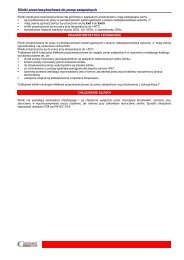
BA SeriesB5B14B320
GENERAL CHARACTERISTICSBA SeriesBA series consists of three phase, asynchronous brake motors totally enclosed fan cooled (TEFC). BA series range starts from 71up to 280 frame size. The motor brakes in case of power supply failure. The braking action is always secured through a very quickand precise stop assuring a safe and prompt stop in case of unintentional power supply failure. The brake torque remains the samein both directions of rotation and the motor brakes without shaft axial sliding. As standard the brake is AC 3-phase voltage supplywith brake leads connected with motor leads in a single terminal board while on request it is possible to supply the brake separatelywith a second terminal board or to have a DC brake supply with a built-in rectifier fitted inside the terminal box. The rectifier isprovided with over-voltage and radio frequencies emission protection devices. BA series motors tolerate high overloading rate andare capable of withstanding overheating so as to guarantee the best reliability even under tough operating conditions. All MGMseries motors have been designed to be controlled by inverters. The motor winding insulation is class F, while class H is availableon request. Motor construction type is totally enclosed externally cooled and IP54 enclosure (IP55 and IP56 available on request).<strong>Motors</strong> up to 132 frame size are fitted as standard with a hexagonal hole on the shaft at the non drive end to allow manual rotation,even if power is off. All BA series motors are provided as standard with hand brake release screw.BA series brake disc has a large lining surface that allows high brake torque, low disc wear and consequently low maintenancecost. The brake torque can be easily adjustable to the desired value just by screwing some nuts. Thanks to its special constructionthe brake friction surface is self-ventilated on the motor side, permitting a high brake workload and keeping brake time constant.The brake lining material is asbestos free.BA series motor frame is made of die cast, light metal on motors up to 132 size and the terminal board box, provided with cableglands and plugs, is positioned 180° above the motor support feet. The frame is made of cast iron starting from 160 frame sizeand the terminal box is located on the right side (drive-end view). Shields and flanges are made of aluminium on motors up to 90frame size, and of cast iron on motors of 100 frame size and above. As standard feet are frame integrated (they are not simplyattached to the frame) on IM B3 mounting (foot mounted) making the motor very sturdy. This feature is very important for thoseapplications where the motor is much stressed during the starts and stops.The brake friction surfaces are made of cast iron as a standard. The brake moving element and the brake coil have a laminatednucleus to reduce electrical losses and to secure a very quick brake intervention.BA series main features are its sturdy construction, quick braking action, constant braking time, high number of permissiblestart/stop cycles also under severe applications, easily adjustable brake torque, low maintenance costs.21
BA series brake groupBA seriesAir gap adjustmentThe air gap (24), 60 that is the distance between the two magnetic cores, the brake coil (24) 25 andbrake moving element (24), must stay within the value expressed in the chart below. It is notadvisable to exceed the expressed value, in order to avoid vibrations of the brake movingelement, very loud noise, the brake coil burning or even the whole brake assembly failure. Itis advisable to check periodically the air gap because it increases as a consequence of thebrake disc wear. In order to set the air gap to the indicated value, you have to loosen the nuts(24) 21 (24) 22 so to move the brake coil (24) 25 towards the brake moving element (24). Once thisoperation has been settled be sure to tighten the locknuts. The above mentioned procedureisn’t valid for BA 250-280 serie-motors, for which we pls you to contact us.Frame SizeMin Air Gap [mm]Max Air Gap [mm]71-800.250.5<strong>Brake</strong> torque adjustment90-1000.30.6112-1320.40.8160÷2000.51.0The brake torque is proportional to the springs (18) compression, which can be adjusted tightening orloosening the locknuts (20). The compression of the three springs must be as even as possible. Oncethe brake is properly supplied, if the brake coil isn’t able to attract the brake moving element with a quickstroke and to keep it attracted without any vibrations, check the air gap adjustment and, if this inconveniencestill persists, loosen the locknut (20) by two threads and try again until the proper functioning is obtained.It is important to consider that some motors can be equipped with 3 springs and some others with 6.(see page 23). Once this operation is completed, check the brake torque to make sure it is set to thedesired value. Never set the brake torque to a higher value than the one indicated on the motor nameplate.2250.61.2191723241860202122262725Permissible start frequency under loadThe technical data tables provide the ideal no-load start frequency (Z0). The permissiblestart frequency when an external load is applied (Z load) can be found with the followingformula:Zload=Z0 • K • Rwhere “Z0” is the table-value for the selected motor and “K” and “R” are factors determinedby the curves on the side; the factor “K” is related to the ratio of the moment of inertia ofthe applied load (Japp) to that of the motor (Jmot) while the factor “R” is related to the ratioof the resisting torque (Tr) to the starting torque (Ts). This calculation gives an approximativeindication only and it has to be operatively tested for confirmation. If the required startingfrequency is close to Zload, it is advisable to use a motor equipped with thermal protectors.It is necessary to check the maximum energy dissipation limit of the brake group and themaximum motor RPM in those applications where high moment of inertia is involved. Onrequest is available a special brake disc material capable to withstand very high dissipationenergy. Please contact MGM technical staff for additional information.RK10,80,60,40,201,210,80,60,40,200 0,2 0,4 0,6 0,8 1,0T r / Ts01 2 3 4 5 6 7 8J app /Jmot<strong>Brake</strong> coil wiring diagramAs standard BA series motors are equipped with AC brakes with single terminal boardfor the brake and the motor while on request it is possible to supply the brakeseparately. On request DC brakes are available for BA series with the rectifier locatedinside the terminal box. The rectifier is provided with over-voltage protection devicesand with a RFI filter. MGM brake motors equipped with DC brakes can be connectedas in diagram A or B according to the needed braking time. MGM motors providedwith DC brake coil are connected as diagram A. The DC brake coil has to be connectedaccording to diagram B to have a reduced brake reaction time.WhiteWhiteRedGrey or BrownBlack<strong>Brake</strong> coilWhiteWhiteDiagram ARedGrey or BrownBlack22<strong>Brake</strong> coilDiagram B
<strong>Brake</strong> torque and brake spring compressionBA series motors are provided as standard with a brake torque set to 60 - 70% of the maximum admissible braketorque indicated on the nameplate. On request the motor can come already set to a specific brake torque value differentfrom the standard one. The brake torque is shown in the diagrams here below as a function of the brake assemblyspring compression; for BA250-280 motors pls contact MGM. The shown values refer to BA series motors mounted inhorizontal position with an AC brake coil. DC brakes have the same trend as AC brakes even if they have lower braketorque, as shown in the table below. For BAK 100-132 motors series the brake torque changes in a different way thanshown in the diagrams. Please contact MGM for further information. The values shown in the diagrams are onlyindicative as application conditions, brake lining wear and temperature, can affect the real brake torque. Whenever it isnecessary to adjust the braking torque to a specific value it is advisable to directly measure the obtained brake torqueafter each brake torque adjustment. <strong>Co</strong>nsider that the motor mounting position influences remarkably the effectivebraking torque when low brake torque values are involved. Please contact MGM for further information.HBA seriesFrame size718090100112132160180200225250280Max AC <strong>Brake</strong> Torque (Nm):Max DC <strong>Brake</strong> Torque (Nm):1491815383050428060150120190155300180300180400240700-1000-Nm 16BA 71Nm20BA 80Nm 40BA 901412101816141235302581020642864215105016,5 15,5 14,5 13,5 12,5 11,5 mm016,5 15,5 14,5 13,5 12,5 11,5 mm019 18 17 16 15mmBA 100BA 112BA 132Nm60Nm90Nm 1605040302010807060504030201014012010080604020019 18 17 16 15 14 mm019 18.1 17.2 16.3 15.4 14.5 mm018.6 18.1 17.5 17 16.4 mmNm180160BA 160Nm300250BA 180-200Nm 450400350BA 2251401202003002501008060150100200150100504023,2 22 20,8 19,6 18,4 17,2 16 mmLight blue line: 6 springs brake groupBlue line: 3 springs brake group<strong>Co</strong>nsider that DC brake groups always have 3 springs and 155 Nmmax. brake torque.5041 38 35 32 29 26 mmLight blue line: 6 springs brake groupBlue line: 3 springs brake group<strong>Co</strong>nsider that DC brake groups always have 3 springs and 180Nm max. brake torque.039,6 38,2 36,8 35,4 34 32,6 31,2 29,8 mmLight blue line: 6 springs brake groupBlue line: 3 springs brake group<strong>Co</strong>nsider that DC brake groups always have 3 springs and 240 Nmmax. brake torque.23
Technical Data Single Speed Motor – Single WindingBA seriesMotor typePower(kW)RPMIn 400 V(A)Powerfactor<strong>Co</strong>s ϕTn (Nm)Ts/TnIs/InACbrakeIn (mA)DCbrakeIn (mA)Z 0(starts/hour)Moment ofinertiaJx 10 -4 Kgm 2Max <strong>Brake</strong>torque(Nm)A-SoundpressuredB(A)Weight (Kg)3000 r.p.m.0.370.550.750.751.11.52.23.04.05.55.57.59.211.011.015.018.522.030.037.0281028102810280028002850284029002880288028902890289028902920293029302950294029400.901.401.81.72.43.24.56.38.111.410.814.617.921.419.526.332.436.752.064.10.780.780.800.860.860.860.860.810.840.850.860.850.850.850.940.930.930.950.940.931.261.872.552.563.755.037.409.8813.2618.2418.1724.7830.4036.3535.9848.8960.3071.2297.45120.192.62.62.53.13.13.03.02.22.52.52.82.82.82.83.03.13.12.72.82.84.54.54.55.35.36.96.97.67.47.47.47.47.47.48.68.88.89.09.09.0909090140140300300300280280580580580580139013901390950950950110110110150150150150150470470680680680680860860860110011001100600060005000600060004500450028001700140048048042040035035035012090904.885.486.1511.6412.9618.9521.8439.8268.9685.00192.0231.0270.0308.0537.0537.0616.01150.01160.01290.01414141818383850808015015015015019019019030030030059595965657272747575757575757777777879799.510.511.014.515.520.022.530.04448717783901601601712432742891500 r.p.m.2 poleBA 71 A2BA 71 B2BA 71 C2 *BA 80 A2BA 80 B2BA 90 SA2BA 90 LA2BA 100 LA2BA 112 MB2BA 112 MC2*BA 132 SA2BA 132 SB2BA 132 MA2 *BA 132 MB2 *BA 160 MA2BA 160 MB2BA 160 LA2BA 180 LA2BA 200 LA2BA 200 LB24 poleBA 71 A4BA 71 B4BA 71 C4 *BA 71 D4 *BA 80 A4BA 80 B4BA 80 C4 *BA 90 SA4BA 90 LA4BA 90 LB4 *BA 90 LC4 *BA 100 LA4BA 100 LB4BA 112 MB4BA 112 MC4*BA 132 SB4BA 132 MA4BA 132 MB4 *BA 132 MBX4 *BA 160 MA4BA 160 MB4BA 160 LA4BA 180 LA4BA 180 LB4BA 200 LB4BA 225 S4BA 225 M4BA 250 M4BA 280 S4BA 280 M40.250.370.550.650.550.750.91.11.51.852.22.23.04.05.55.57.59.211.09.211.015.018.522.030.037.045.055.075.090.01400140013601350140014001390140014001400139014101410141514201430143514451440146014601460146014601455147514751470148014700.81.101.652.001.702.202.602.73.64.35.45.06.58.111.511.314.818.321.718.621.228.533.741.856.568.182.61001321570.650.680.700.690.690.670.670.770.750.770.750.780.800.840.830.820.840.850.860.840.850.870.890.850.870.850.850.850.860.881.712.523.864.603.755.126.187.5010.2312.6215.1214.9020.3227.0036.9936.7349.9160.8072.9560.1871.9598.12121.01143.90196.91239.56291.36357.00487.00584.002.52.72.42.12.12.52.82.32.72.72.72.52.82.62.82.42.42.52.53.02.92.72.92.52.52.52.53.52.82.73.73.93.73.74.04.34.54.64.85.85.05.46.46.46.96.06.06.36.07.07.07.08.07.67.47.97.98.88.07.5909090901401401403003003003003003002802805805805805801390139013909509509501350135020002000200011011011011015015015015015015015015015047047068068068068086086086011001100110015001500---20000190001800016000100001000010000150001200090007000800070004000350012009509008008508508505405403003003001201001007.208.109.439.9214.9717.1918.3026.1530.5334.5734.5751.1460.07125.7145.0277.0352.0432.0432.0604.0683.0858.01740.01740.01980.04470.05140.07690.08390.08890.0141414141818183838383850508080150150150150190190190300300300400400700100010004545454547474755555555575761616262626263636364646668687070709.510.511.512.014.015.016.020.022.524.024.0323645507887100100148154171243.0243.0274.0392.0440.0665.0770.0810.0* Non Standard Power24
Technical Data Single Speed Motor – Single WindingMotor typePower(kW)RPMIn 400 V(A)Powerfactor<strong>Co</strong>s ϕTn (Nm)Ts/TnIs/InACbrakeIn (mA)DCbrakeIn (mA)Z 0(starts/hour)Moment ofinertiaJx 10 -4 Kgm 2Max <strong>Brake</strong>torque(Nm)A-SoundpressuredB(A)1000 r.p.m.Weight (Kg)BA series0.180.250.370.550.751.11.31.51.852.23.04.05.57.59.211.015.018.522.030.037.045.055.08759009109009109109109309209459609609609659709709709709659809859859850.600.801.251.812.313.213.913.915.015.217.219.5112.3115.9118.3122.7129.4138.1143.5160.7173.0187.01105.010.710.710.670.680.680.680.680.710.680.790.720.720.750.790.810.800.840.820.850.780.780.800.801.962.653.885.847.8711.5413.6415.4019.2022.2329.8439.7954.7174.2290.58108.30147.68182.14217.72292.35358.00436.00533.002.02.02.62.22.12.22.52.32.62.02.52.32.32.22.22.52.32.22.22.62.72.62.52.62.83.42.83.53.64.04.34.55.36.56.56.57.17.17.57.88.08.06.56.66.36.0909014014030030030030030028058058058013901390139095095095013502000200020001101101501501501501501501504706806806808608608601100110011001500---2800028000180001800018000150001200011000850065001800150012001200110095060035035035020016016010.0811.5423.4027.2135.9346.0853.0087.4099.19168.3346.0401.0508.0943.01240.01240.02070.02360.02360.07470.010090.010690.011640.01414181838383850508015015015019019019030030030040070010001000454547475454545656585858585959596061616365656510.511.014.515.519.522.024.033.035.045788394156174174243289289440675750790750 r.p.m.6 poleBA 71 A6BA 71 B6BA 80 A6BA 80 B6BA 90 SA6BA 90 LA6BA 90 LB6*BA 100 LA6BA 100 LB6 *BA 112 MB6BA 132 SB6BA 132 MA6BA 132 MB6BA 160 MB6BA 160 LA6 *BA 160 LB6BA 180 LB6BA 200 LA6BA 200 LB6BA 225 M6BA 250 M6BA 280 S6BA 280 M68 poleBA 71 A8BA 71 B8BA 80 A8BA 80 B8BA 90 SA8BA 90 LA8BA 90 LB8*BA 100 LA8BA 100 LB8BA 112 MB8BA 132 SB8BA 132 MB8BA 160 MA8BA 160 MB8BA 160 LA8BA 180 LB8BA 200 LA8BA 225 M8BA 250 M8BA 280 S8BA 280 M80.080.110.180.250.370.550.650.751.11.52.23.04.05.57.511.015.022.030.037.045.06606606756756806906907007007057007007257257257307307357407407400.600.800.951.251.502.202.702.754.14.95.27.19.613.618.625.932.851.366.082.096.00.530.550.590.620.600.560.560.580.590.600.750.750.720.700.700.720.770.710.720.710.731.161.592.553.545.207.619.0010.2315.0120.3230.0140.9352.6972.4598.79143.90196.23285.85387.00478.00581.002.02.02.02.02.12.12.12.12.52.02.12.12.32.32.32.01.92.13.02.01.82.02.02.22.22.92.82.83.04.04.54.74.76.56.16.15.96.16.46.56.05.890901401403003003003003002805805801390139013909509501350200020002000110110150150150150150150150470680680860860860110011001500---300003000030000300002000017000140001400094007200210021001800180018008005003502501901907.208.1023.4027.2135.9346.0853.0087.4099.19168.3325.0413.01030.01030.01360.02460.02880.07470.011140.012140.014640.01141141181181381381381501501801150115011901190119013001300140017001000100043434545464646494952555558585859606265656510.010.514.515.520.022.524.033.035.0457380156156174243243440675750790* Non Standard Power1. Motor characteristic values reported in the tables referto continuous duty (S1), 50 Hz frequency, ambient temperaturemax. 40 °C, altitude up to 1000 m. above sea level operatingcondition.2. DC brake is provided on request only on BA series motors. <strong>Brake</strong> current consumption values refer to a rated voltageof 3-phase 400V for AC brakes and single-phase 230V forDC brakes.3. The table shows the sound pressure noise level, measuredat one metre range from the motor according to the Acurve(ISO 1680). The shown noise levels refer to motor no-loadoperating condition and should be regarded with a toleranceof ± 3dB.4. Max brake torque and Z 0 values refer to AC brake. Go topag. 23 for DC max brake torque values.5. The expressed Z 0 values refers to AC <strong>Brake</strong>. Z 0 is themax number of no-load starts. It is meant for calculationpurposes only, and is used to obtain the max number ofstarts with load according to the formula expressed at page22. The number of starts with load (Zload) is indicative andit has to be operatively tested for confirmation. The use ofThermo-protectors is strongly recommended when theoperative number of starts is close to the calculated Zload.It is necessary to verify the max permissible brake energydissipation and the max permissible RPM.6. The maximum brake torque for BAK 132 motors seriesis 120Nm25
Technical Data Two Speed Motor – Single WindingBA seriesMotor type2 / 4 polePower(kW)RPMIn 400 V(A)Powerfactor<strong>Co</strong>s ϕTn (Nm)Ts/TnIs/InACbrakeIn (mA)DCbrakeIn (mA)Z 0(starts/hour)Moment ofinertiaJx 10 -4 Kgm 2Max <strong>Brake</strong>torque(Nm)A-SoundpressuredB(A)Weight (Kg)3000 / 1500 r.p.m.BAD 71 A2/40.250.18282014150.750.700.730.660.851.212.22.43.83.1901108500180007.2014594510.0BAD 71 B2/40.370.25282014151.000.850.770.631.251.692.32.84.74.2901107000160008.1014594511.0BAD 80 A2/4BAD 80 B2/4BAD 90 SB2/4BAD 90 LA2/4BAD 90 LB2/4BAD 100 LA2/4BAD 100 LB2/4BAD 112 MB2/4BAD 132 SB2/4BAD 132 MA2/4BAD 132 MB2/4BAD 160 MA2/4BAD 160 MB2/4BAD 160 LA2/4BAD 180 LA2/4BAD 180 LB2/4BAD 200 LB2/40.650.450.880.621.30.91.81.22.21.52.21.53.12.34.53.35.04.56.05.07.56.09.58.011.09.013.011.017.014.020.517.024.020.027901400280013902800142028001420286014302875142528751425288014002940145029401450294014502870142028701420289014202900144029001430291014351.801.352.21.73.22.34.43.15.43.85.03.86.75.29.26.910.99.311.710.016.012.220.016.623.318.726.121.233.026.841.533.349.041.00.810.720.800.740.850.730.830.710.820.730.850.810.850.820.880.860.810.840.880.850.820.830.890.850.880.850.910.870.890.860.890.860.860.822.223.073.004.264.436.056.148.077.3510.027.3110.0510.3015.4114.9222.5116.2429.6419.4932.9324.3639.5231.6153.8036.6060.5342.9673.9855.9892.8567.51113.5378.76133.102.02.12.02.22.32.52.63.02.53.02.32.52.32.42.42.82.82.62.62.52.42.52.82.62.82.62.82.62.92.72.92.72.52.44.14.04.94.55.25.05.66.05.96.06.05.67.06.57.06.58.07.58.07.58.07.57.56.06.86.07.06.38.06.58.06.58.06.51401403003003003003002805805805801390139013909509509501501501501501501501504706806806808608608601100110011003000100003000100003000950025009000250085001800650017006000900380040010004009004009003008003008002507501005001005007025014.9717.1926.1530.5334.5751.1460.07125.7277.0352.0352.0607.0683.0858.01740.01740.01980.018183838385050801501501501901901903003003006547654772557255725574577457756175627562756277637763776378647864796614.515.520232432364578878715415417124324327426
Technical Data Two Speed Motor – Single WindingMotor type4 / 8 polePower(kW)RPMIn 400 V(A)Powerfactor<strong>Co</strong>s ϕTn (Nm)Ts/TnIs/InACbrakeIn (mA)DCbrakeIn (mA)Z 0(starts/hour)Moment ofinertiaJx 10 -4 Kgm 2Max <strong>Brake</strong>torque(Nm)A-SoundpressuredB(A)1500 / 750 r.p.m.Weight (Kg)BA seriesBAD 71 A4/80.130.0713857000.350.450.820.600.900.961.61.83.02.090110120003000010.0814454310.5BAD 71 B4/80.180.0913706850.500.600.830.591.251.251.82.03.22.090110110003000011.5414454311.0BAD 71 C4/8BAD 80 A4/8BAD 80 B4/80.220.120.250.180.370.251370685140567514056750.600.750.700.900.851.150.830.590.860.650.860.651.531.671.702.552.513.541.61.82.22.02.22.03.02.04.12.44.12.490140140110150150100002800090002200090002200012.3523.4027.2114181845434745474512.014.515.5BAD 90 SA4/8BAD 90 LB4/80.750.371.10.6135069513906951.701.802.73.00.850.530.820.535.315.087.568.241.82.32.02.53.92.74.52.7300300150150100001500085001300035.9352.623838554655462024BAD 100 LB4/8BAD 112 MB4/81.60.92.21.2139570014407203.63.54.84.60.870.580.860.5710.9512.2814.5915.922.02.22.53.15.03.55.54.1300280150470410085003800800099.19168.35080574961523545BAD 132 SB4/8BAD 132 MA4/8BAD 132 MB4/8BAD 160 MB4/8BAD 160 LA4/8BAD 180 LA4/8BAD 180 LB4/8BAD 200 LA4/8BAD 200 LB4/8BAD 250 225 LB4/8 S4/8BAD 225 M4/8BAD 250 M4/83.02.04.02.76.04.06.54.59.56.011.08.014.09.018.011.021.013.030.018.035.025.042.030.01440720144072014407201470730147073014707301465730143071014257101470730147073014707306.65.88.87.813.011.615.113.321.517.622.019.227.122.336.327.241.631.756.643.266.160.075.065.00.850.640.850.640.850.640.800.620.820.620.850.700.870.680.880.710.880.700.870.700.870.700.890.7519.9026.5326.5335.8139.7953.0642.2358.8761.7278.4971.46105.3891.26117.74120.21147.96140.74174.86195.00235.60227.50327.20272.00392.002.22.52.22.52.22.52.62.42.62.42.82.42.72.52.82.62.62.42.52.42.52.31.91.76.05.06.05.06.05.08.06.58.06.57.57.07.57.07.58.07.06.57.57.07.56.85.54.058058058013901390950950950950135013502000680680680860860110011001100110015001500-100020001000200010002000800145075014004507504007007025070250602006020060200325.0413.0611.01030.01360.02460.02460.02880.02880.06500.06900.011680.015015015019019030030030030040040070062556255625563586358645964596660666068626862706573801181561742432432932933924408001. Motor characteristic values reported in the tables referto continuous duty (S1), 50 Hz frequency, ambient temperaturemax. 40 °C, altitude up to 1000 m. above sea level operatingcondition.2. DC brake is provided on request only on BA series motors. <strong>Brake</strong> current consumption values refer to a rated voltageof 3-phase 400V for AC brakes and single-phase 230V forDC brakes.3. The table shows the sound pressure noise level, measuredat one metre range from the motor according to the Acurve(ISO 1680). The shown noise levels refer to motor no-loadoperating condition and should be regarded with a toleranceof ± 3dB.4. Max brake torque and Z 0 values refer to AC brake. Go topag. 23 for DC max brake torque values.5. The expressed Z 0 values refers to AC <strong>Brake</strong>. Z 0 is themax number of no-load starts. It is meant for calculationpurposes only, and is used to obtain the max number ofstarts with load according to the formula expressed at page22. The number of starts with load (Zload) is indicative andit has to be operatively tested for confirmation. The use ofThermo-protectors is strongly recommended when theoperative number of starts is close to the calculated Zload.It is necessary to verify the max permissible brake energydissipation and the max permissible RPM.6. The maximum brake torque for BAK 132 motors seriesis 120Nm27
Technical Data Two Speed Motor – Two WindingsBA seriesMotor type2 / 6 polePower(kW)RPMIn 400 V(A)Powerfactor<strong>Co</strong>s ϕTn (Nm)Ts/TnIs/InACbrakeIn (mA)DCbrakeIn (mA)Z 0(starts/hour)Moment ofinertiaJx 10 -4 Kgm 2Max <strong>Brake</strong>torque(Nm)A-SoundpressuredB(A)Weight (Kg)3000 / 1000 r.p.m.BADA 71 B2/60.250.0828809400.850.600.740.640.830.812.62.24.32.0901103600150008.101459456.5BADA 71 C2/60.350.1028809401.050.600.750.591.161.022.62.25.02.3901103000120009.431459457.5BADA 80 A2/6BADA 80 B2/6BADA 90 SA2/6BADA 90 LA2/6BADA 90 LB2/6BADA 100 LA2/6BADA 100 LB2/6BADA 112 MB2/6BADA 132 SB2/6BADA 132 MA2/6BADA 132 MB2/6BADA 160 MB2/6BADA 160 LA2/6BADA 180 LB2/60.370.120.550.180.90.31.20.41.40.51.60.62.20.83.01.04.01.35.51.87.02.28.02.511.03.616.06.5288594528859452875950287595028909402810900280091028709502880940287094028709402890950289095029109601.350.801.751.052.101.152.801.553.21.83.71.94.82.56.43.28.93.711.55.114.96.315.96.921.49.330.316.00.670.570.670.570.860.650.860.650.860.550.850.680.900.670.860.610.850.690.880.690.880.690.920.740.920.740.930.721.221.211.821.822.993.023.994.024.635.085.446.377.508.409.9810.0513.2613.2118.3018.2923.2922.3526.4425.1336.3536.1952.5164.662.61.92.61.92.52.22.52.22.72.52.62.32.62.33.03.23.02.83.02.83.02.83.02.03.02.03.02.45.02.55.02.55.02.55.02.55.03.05.43.45.43.47.04.57.04.57.54.57.54.58.04.38.04.38.05.01401403003003003003002805805805801390139095015015015015015015015047068068068086086011002000150002000150001800150001800135018001200018001500010001500011008600350170035014003501100250100025090010025014.9717.1926.1530.5334.5751.1460.07125.7277.0352.0432.0683.0858.01740.01818383838505080150150150190190300654765477254725472547456745675587558755875587759775978609.010.011.514.015.519233278879815417124328
Technical Data Two Speed Motor – Two WindingsMotor type2 / 8 polePower(kW)RPMIn 400 V(A)Powerfactor<strong>Co</strong>s ϕTn (Nm)Ts/TnIs/InACbrakeIn (mA)DCbrakeIn (mA)Z 0(starts/hour)Moment ofinertiaJx 10 -4 Kgm 2Max <strong>Brake</strong>torque(Nm)A-SoundpressuredB(A)3000 / 750 r.p.m.Weight (Kg)BA seriesBADA 71 B2/80.250.0629007000.850.550.690.540.820.822.81.84.01.5901103600250009.1014594311.0BADA 71 C2/80.350.0729007001.050.750.700.521.150.962.52.24.31.6901103000220009.4314654312.0BADA 80 A2/8BADA 80 B2/8BADA 90 SB2/8BADA 90 LA2/8BADA 90 LB2/8BADA 100 LA2/8BADA 100 LB2/8BADA 112 MB2/8BADA 132 SB2/8BADA 132 MA2/8BADA 132 MB2/8BADA 160 MB2/8BADA 160 LA2/8BADA 180 LB2/8BADA 200 LB2/80.370.090.550.120.750.181.100.251.30.31.60.42.20.53.00.84.01.15.51.57.01.88.02.211.03.016.04.018.54.52885690288569028006102800640282064028106602800660286069028806802870680287068028807052880710291571529157151.350.701.750.901.901.052.701.453.101.753.72.04.82.56.33.58.94.011.55.614.97.316.77.621.510.230.011.535.013.50.670.540.670.540.770.650.810.580.810.580.850.580.900.590.870.630.850.600.880.590.880.590.910.650.920.650.930.660.930.661.221.251.821.662.562.823.753.734.404.485.445.797.507.2310.0211.0713.2615.4518.3021.0723.2925.2826.5329.8036.4840.3552.4253.4360.6160.102.31.82.32.03.02.13.02.13.22.42.72.02.82.33.32.63.01.93.02.03.02.03.01.93.01.93.01.93.01.95.01.75.01.75.11.95.11.95.72.05.32.25.72.37.53.27.03.37.53.07.53.08.03.38.03.38.03.38.03.31401403003003003003002805805805801390139095095015015015015015015015047068068068086086011001100200020000200020000180018000180017000180016000180016000100010500110090004301800400180040018003001500300150010030010030014.9717.1926.1530.5334.5751.1460.07125.7277.0352.0432.0683.0858.01740.02030.0181838383850508015015015019019030030065457245724672467246744974497552755575557555775877587959795914.515.522.523.024.03236457887981541712432551. Motor characteristic values reported in the tables referto continuous duty (S1), 50 Hz frequency, ambient temperaturemax. 40 °C, altitude up to 1000 m. above sea level operatingcondition.2. DC brake is provided on request only on BA series motors. <strong>Brake</strong> current consumption values refer to a rated voltageof 3-phase 400V for AC brakes and single-phase 230V forDC brakes.3. The table shows the sound pressure noise level, measuredat one metre range from the motor according to the Acurve(ISO 1680). The shown noise levels refer to motor no-loadoperating condition and should be regarded with a toleranceof ± 3dB.4. Max brake torque and Z 0 values refer to AC brake. Go topag. 23 for DC max brake torque values.5. The expressed Z 0 values refers to AC <strong>Brake</strong>. Z 0 is themax number of no-load starts. It is meant for calculationpurposes only, and is used to obtain the max number ofstarts with load according to the formula expressed at page22. The number of starts with load (Zload) is indicative andit has to be operatively tested for confirmation. The use ofThermo-protectors is strongly recommended when theoperative number of starts is close to the calculated Zload.It is necessary to verify the max permissible brake energydissipation and the max permissible RPM.6. The maximum brake torque for BAK 132 motors seriesis 120Nm29
Technical Data Two Speed Motor – Two WindingsBA seriesMotor type4 / 6 polePower(kW)RPMIn 400 V(A)Powerfactor<strong>Co</strong>s ϕTn (Nm)Ts/TnIs/InACbrakeIn (mA)DCbrakeIn (mA)Z 0(starts/hour)Moment ofinertiaJx 10 -4 Kgm 2Max <strong>Brake</strong>torque(Nm)A-SoundpressuredB(A)Weight (Kg)1500 / 1000 r.p.m.BADA 71 C4/60.180.1114159300.600.500.760.661.211.131.92.03.02.39011075001500012.3514454512.0BADA 80 A4/6BADA 80 B4/6BADA 90 SA4/6BADA 90 LB4/6BADA 100 LA4/6BADA 100 LB4/6BADA 112 MB4/60.250.180.370.250.550.370.750.551.10.81.51.12.01.314309401430940142095014209501445955144095013859300.850.801.050.951.601.452.201.93.02.43.93.34.43.50.790.710.790.710.780.620.780.620.760.710.750.680.880.751.671.832.472.543.703.725.045.537.278.009.9511.0613.7913.352.21.82.21.81.92.12.02.12.02.12.02.12.62.14.33.04.33.03.83.33.83.35.34.45.24.45.34.4140140300300300300280150150150150150150470700015000700015000600012000550010000200050000180080002600550023.4027.2135.9346.0886.4099.19168.318183838505080474747475554555457565756615814.515.520.023.033.035.045BADA 132 SB4/6BADA 132 MA4/6BADA 132 MB4/62.21.53.02.23.72.51440950144095014409505.14.46.46.08.27.00.780.690.810.710.780.6914.5915.0819.9022.1224.5425.132.92.62.72.42.92.67.05.57.05.07.05.558058058068068068060010006001000500900346.0401.0508.0150150150625862586258788394BADA 160 MB4/65.53.7139094011.18.90.930.8137.7937.592.52.35.85.21390860400700943.01906359156BADA 160 LB4/67.55.0139094015.212.20.930.8151.5350.802.52.36.05.213908604007001240.01906359174BADA 180 LB4/613.08.8144095024.618.90.910.8286.2288.462.952.007.06.095011003508502070.030064602431. Motor characteristic values reported in the tables referto continuous duty (S1), 50 Hz frequency, ambient temperaturemax. 40 °C, altitude up to 1000 m. above sea level operatingcondition.2. DC brake is provided on request only on BA series motors. <strong>Brake</strong> current consumption values refer to a rated voltageof 3-phase 400V for AC brakes and single-phase 230V forDC brakes.3. The table shows the sound pressure noise level, measuredat one metre range from the motor according to the Acurve(ISO 1680). The shown noise levels refer to motor no-loadoperating condition and should be regarded with a toleranceof ± 3dB.4. Max brake torque and Z 0 values refer to AC brake. Go topag. 23 for DC max brake torque values.5. The expressed Z 0 values refers to AC <strong>Brake</strong>. Z 0 is themax number of no-load starts. It is meant for calculationpurposes only, and is used to obtain the max number ofstarts with load according to the formula expressed at page22. The number of starts with load (Zload) is indicative andit has to be operatively tested for confirmation. The use ofThermo-protectors is strongly recommended when theoperative number of starts is close to the calculated Zload.It is necessary to verify the max permissible brake energydissipation and the max permissible RPM.6. The maximum brake torque for BAK 132 motors seriesis 120Nm30
Technical Data Two Speed Motor – Two WindingsMotor type4 / 12 polePower(kW)RPMIn 400 V(A)Powerfactor<strong>Co</strong>s ϕTn (Nm)Ts/TnS3 40%Is/InACbrakeIn (mA)DCbrakeIn (mA)Z 0(starts/hour)Moment ofinertiaJx 10 -4 Kgm 2Max <strong>Brake</strong>torque(Nm)A-SoundpressuredB(A)1500 / 500 r.p.m.Weight (Kg)BA seriesBADA 80 A4/120.250.0514254350.850.600.770.631.681.101.81.93.71.614011070002400023.4018474314.5BADA 80 B4/120.370.0714254351.050.750.770.632.481.541.81.93.71.614011070002400027.2118474315.5BADA 90 SA4/12BADA 90 LA4/12BADA 90 LB4/120.400.130.550.180.750.221360380140040013704001.251.051.651.202.051.600.730.590.760.640.760.652.813.273.754.305.235.252.52.02.51.82.52.03.51.63.51.63.51.630030030015015015055003000055003000050002800035.9346.0852.6238383855445544554420.023.024.0BADA 100 LA4/12BADA 100 LB4/120.900.251.100.35144045014404502.32.12.82.60.760.500.760.505.975.317.307.432.21.82.21.85.31.75.31.730030015015044001500021001300087.4099.1950505747574733.035.0BADA 112 MB4/12BADA 132 SA4/121.500.452.500.80142044014404403.42.45.43.80.840.550.810.5310.099.7716.5817.362.22.02.71.66.02.27.02.42805804706802600150008002200168.3346.0801506150625845.078.0BADA 132 MA4/12BADA132 MB4/12BADA 160 MB4/123.01.04.01.34.81.61440440144044014254556.44.58.55.910.07.20.810.530.810.550.890.5719.9021.7026.5328.2232.1733.582.71.62.71.62.82.07.02.47.02.47.53.05805801390680680860800220080022006001700401.0508.0943.01501501906258625863618394156BADA 160LB4/127.32.4141044515.210.10.900.6149.4451.512.82.07.03.0139086060017001240.019063611741. Motor characteristic values reported in the tables referto continuous duty (S1), 50 Hz frequency, ambient temperaturemax. 40 °C, altitude up to 1000 m. above sea level operatingcondition.2. DC brake is provided on request only on BA series motors. <strong>Brake</strong> current consumption values refer to a rated voltageof 3-phase 400V for AC brakes and single-phase 230V forDC brakes.3. The table shows the sound pressure noise level, measuredat one metre range from the motor according to the Acurve(ISO 1680). The shown noise levels refer to motor no-loadoperating condition and should be regarded with a toleranceof ± 3dB.4. Max brake torque and Z 0 values refer to AC brake. Go topag. 23 for DC max brake torque values.5. The expressed Z 0 values refers to AC <strong>Brake</strong>. Z 0 is themax number of no-load starts. It is meant for calculationpurposes only, and is used to obtain the max number ofstarts with load according to the formula expressed at page22. The number of starts with load (Zload) is indicative andit has to be operatively tested for confirmation. The use ofThermo-protectors is strongly recommended when theoperative number of starts is close to the calculated Zload.It is necessary to verify the max permissible brake energydissipation and the max permissible RPM.6. The maximum brake torque for BAK 132 motors seriesis 120Nm31
Technical Data Two Speed Motor – Two WindingsBA seriesMotor type2 / 12 polePower(kW)RPMIn 400 V(A)Powerfactor<strong>Co</strong>s ϕTn (Nm)Ts/TnS3 40%Is/InACbrakeIn (mA)DCbrakeIn (mA)Z 0(starts/hour)Moment ofinertiaJx 10 -4 Kgm 2Max <strong>Brake</strong>torque(Nm)A-SoundpressuredB(A)Weight (Kg)3000 / 500 r.p.m.BADA 80 B2/120.450.0728404351.350.700.760.631.511.541.91.94.91.414015017002400027.2118654315.5BADA 90 SB2/120.750.1128004002.101.050.820.612.562.633.02.05.21.430015018002000026.1538724422.5BADA 90 LA2/121.100.1528004002.801.350.820.633.753.583.22.15.41.430015018002000030.5338724423BADA 100 LB2/121.850.2528504104.12.20.870.526.205.823.02.26.31.530015011001100060.0750734736BADA 112 MB2/123.000.4528554306.53.20.860.4910.049.993.02.16.71.8280470120010000125.780735045BADA 132 SB2/124.000.6528804508.94.80.850.5613.2613.793.01.87.01.65806803502200277.7150735578BADA 132 MA2/125.500.90287045011.56.70.880.5618.3019.103.01.87.51.65806803502200352.0150735587BADA 132 MB2/127.001.10288045015.78.50.850.5623.2123.343.01.87.51.65806803502200432.0150735598BADA 160 MB2/128.001.30289047015.99.50.920.4226.4426.413.02.08.02.113908602501200683.01907458154BADA 160 LA2/1211.001.80289047021.412.80.920.4236.3536.573.02.08.02.113908602501200858.01907458171BADA 180 LB2/1216.002.60291047030.612.20.930.4652.5152.833.01.88.02.0950110020010001740.03007859243Hoisting motors 4/16 poleMotor Type Power (kW) RPMService duty S4 (40% 4 pole – 25% 16 pole)BAPKDA 132 MA4/16BAPKDA 132 MB4/16BAPKDA 160 MA4/16BAPKDA 160 MB4/16BAPKDA 160 LB4/16BAPKDA 180 LA4/16BAPKDA 200 LB4/16BAPKDA 225 S4/16BAPKDA 225 M4/16BAPKDA 250 M4/16BAPKDA 280 S4/16BAPKDA 280 M4/162.8 / 0.74.0 / 1.15.5 / 1.37.3 / 1.810.0 / 2.513.2 / 3.016.0 / 4.019.0 / 4.824.0 / 6.030.0 / 7.540.0 / 10.050.0 / 12.51450 / 3501450 / 3501420 / 3351420 / 3301420 / 3301450 / 3501450 / 3501470 / 3601470 / 3601465 / 3601465 / 3601465 / 360In 400 V (A)7.3 / 5.110.8 / 7.611.6 / 8.016.2 / 11.422.2 / 15.925.0 / 21.731.5 / 27.438.2 / 28.047.3 / 34.758.7 / 43.378.3 / 57.797.9 / 72.2AC brake In (mA)1500 / 375 r.p.m.580580139013901390950950135013502000200020001. Motor characteristic values reported in the tables referto continuous duty (S1), 50 Hz frequency, ambient temperaturemax. 40 °C, altitude up to 1000 m. above sea level operatingcondition.2. DC brake is provided on request only on BA series motors. <strong>Brake</strong> current consumption values refer to a rated voltageof 3-phase 400V for AC brakes and single-phase 230V forDC brakes.3. The table shows the sound pressure noise level, measuredat one metre range from the motor according to the Acurve(ISO 1680). The shown noise levels refer to motor no-loadoperating condition and should be regarded with a toleranceof ± 3dB.4. Max brake torque and Z 0 values refer to AC brake. Go topag. 23 for DC max brake torque values.5. The expressed Z 0 values refers to AC <strong>Brake</strong>. Z 0 is themax number of no-load starts. It is meant for calculationpurposes only, and is used to obtain the max number ofstarts with load according to the formula expressed at page22. The number of starts with load (Zload) is indicative andit has to be operatively tested for confirmation. The use ofThermo-protectors is strongly recommended when theoperative number of starts is close to the calculated Zload.It is necessary to verify the max permissible brake energydissipation and the max permissible RPM.6. The maximum brake torque for BAK 132 motors seriesis 120Nm32
<strong>Brake</strong> Linings Wear, Starting and Braking timebrake linings wear<strong>Brake</strong> linings wear is mainly affected by the environmental conditions in which the motor operates, by the frequency of starts, bythe energy dissipated at each stop and by the torque provided by the brake. The lining temperature rises with the braking frequencyand with the moment of inertia applied to the shaft. When the lining temperature raises, the lining wear increases and consequentlythe braking time is longer. BA series motors are designed to have continuous cooling of the braking surfaces so as to reducebrake disc wear to have a shorter braking time.The life cycle of the brake linings can be roughly expressed by the number of brake interventions and can be approximatelycalculated as follows:n = Wtot / Wbwhere Wb (J) is the work done during each braking action and Wtot (J) is obtained from the table for each type of brake motor.However, it is necessary to check the brake disc wear periodically to replace the brake disc before it is completely worn. If youwant to estimate the interval between two successive air gap adjustment in a specific application, note that the brake linings wearis greater than usual during the run-in (a few thousands stops).On PV series brake motors Wtot shown in the table have to be multiplied by 0.5 and the moment of inertia have to be calculatedconsidering the presence of the flywheel. The indicative number of AC brake stops NintAC between two successive air gapadjustments on a BA motor is given by the following formula:NintAC = ErBA / Wbwhile the NintDC for DC brake motors is given by : NintDC = NintAC • 0.65BA series71 80 90 100 112 132 160 180 200225Wtot (MJ)Er (MJ)5375670580952951148105143813022552003290290435538543553855226462For BA 250-280 pls contact MGM. The indicative number of DC brake stops NintBM between two successive air gap adjustments on a BMmotor is given by the following formula:NintBM = ErBM / WbErBM values are shown at pag. 39 (BM section).Starting and braking timeStarting current for an asynchronous motor is always much higher than the nominal current. When the starting time is excessivelylong, there are electromechanical disturbances and higher temperatures on winding, damaging the motor. For information onmaximum starting time allowed for each type of motor, please contact MGM. An indicative value for starting time ts (expressedin seconds) and the angle of rotation ϕs (expressed in radians) can be obtained as follows:(Jmot + Japp)•nta•nts =ϕ s =9.55 (T - Tload)19.1Where Japp (Kgm 2 ) is the moment of inertia referred to the motor shaft, Mload (Nm) is the opposing torque to the motor, Jmot (Kgm 2 )is the moment of inertia of the motor, n (RPM is the rated motor RPM), T is the average starting torque, T=(0,8÷0,9)Ts (see thetechnical data table for Jmot, n and Ts of the selected motor).An indicative braking time tf (s) can be calculated as follows:<strong>Brake</strong> electrical reaction time tB (ms)Motor TypeBA 71-80-90BA 100-112BA 132-160BA 180-200BA 225BA 250BA 280AC <strong>Brake</strong>791212141414DC <strong>Brake</strong>(Standard)80808590100--DC <strong>Brake</strong>(Quick)2030303035--tf =Jtot • n9.55 (Tb ±Tload)The reported tB times are valid only if the motor is connected with the brake. In case the brake is supplied separately, the tB time has to be cut by30 – 50%. This calculation gives an approximative indication. Please contact MGM for further information.+tB1000Where: Jtot total moment of inertia at the motor shaft (Kgm 2 )n motor RPM (min -1 )Tb brake torque (Nm)Tload resisting load torque (Nm) with + sign if matchesthe brake torque, or – sign if opposite.tB brake electrical reaction time (ms)33
BA series 71 – 280 dimensionsBA seriesSize Dimension BA BA 71 71 BA 80 BA 80BA 90 SBA 90 BA S90 L BA BA 90100 L L BA 112 100 ML BA BA 132 112 S MBA 132 BA M132 BA S160 BA M 132 BA 160 M LBA BA 160 180 ML BA 200 160 LL BA BA 225180 S BA L 225 BA M200 BA L250MBA 225 BA 280 S S BA BA 225 280 MABCD*dE*FaFbfgHhIKLL1MaMbNaNbOaObPaPbQQBAF-BAPVRR1SVWW1YZZ1112 125 140 140 160 190 216 216 254 254 279 318 356 356 406 457 45790 100 100 125 140 140 140 178 210 254 279 305 286 311 349 368 41945 50 56 56 63 70 89 89 108 108 121 133 149 149 168 190 19014 19 24 24 28 28 38 38 42 42 48 55 60 60 65 65 75M5 M6 M8 M8 M10 M10 M12 M12 M16 M16 M16 M16 M16 M16 M20 M20 M2030 40 50 50 60 60 80 80 110 110 110 110 140 140 140 140 1409.5 11.5 11.5 11.5 14.5 14.5 14.5 14.5 18.5 18.5 18.5 18.5 18.5 18.5 18.5 18.5 18.5M6 M6 M8 M8 M8 M8 M10 M105 6 8 8 8 8 10 10 12 12 14 16 18 18 18 18 2011 15.5 20 20 24 24 33 33 37 37 42.5 49 53 53 53 58 67.571 80 90 90 100 112 132 132 160 160 180 200 225 225 250 280 2805 6 7 7 7 7 8 8 8 8 9 10 11 11 11 11 127 10 10 10 12 12 12 12 14.5 14.5 15 18.5 18 18 22 24 2410.5 14 14 14 16 16 22 22 24 24 24 30 33 33 33 24 24148 162 171 196 217 229184 194 207 232 254 262 294 339 373 395 420 446 440 440 436 436 436130 165 165 165 215 215 265 265 300 300 300 350 400 400 500 500 50085 100 115 115 130 130 165 165110 130 130 130 180 180 230 230 250 250 250 300 350 350 450 450 45070 80 95 95 110 110 130 1303.5 3.5 3.5 3.5 4 4 4 4 5 5 5 5 5 5 5 5 52.5 3 3 3 3.5 3.5 3.5 3.5160 200 200 200 250 250 300 300 350 350 350 400 450 450 550 550 550105 120 140 140 160 160 200 200344 380 412 436 487 505 600 640 745 789 865 890 995 1000 1155 1155 1210368 403 436 460 511 531 634 672 765 809 907 932 1014 103580 80 98.5 98.5 98.5 98.5135 135 170 170 170 170 199 199 268 268 268 268 327 327 327 327 32710 12 12 12 14 14 15 15 15 15 15 15 20 20 18 18 188 9.5 10.5 10.5 12.5 13.5 16 16 21 21 24 24 32 32 32 40 40105 113 127 127 138 158 165 165 188 188 224 224 252 252 252121 130 148 148 162 176 215 215 246 246 266 266 341 341 361 361 361145 160 180 180 196 218 265 265 324 324 357 357 430 430 493 493 49375 75 98.5 98.5 98.5 98.586 86 112 112 112 112 151 151 167 167 167 167 202 202 202 202 202* 225S-225M 2 pole D=55 E=110, 250M 2 pole D=160 E=140, 280S-280M 2 pole D=65 E=140Notes:QBAF is the Q dimension for BAF seriesQBAPV is the Q dimension for BAPV seriesCable glands are M 20 on size 71 up to 80M 25 on size 90 up to 112M 32 on size 132PG 29 on size 160 up to 200M 50 and M 32 on size 225/28034
BA series 71 – 280 dimensionsB3 (Foot Mounting)BA seriesB5 (Flange mounting)B14 (Face Mounting)Size 160÷280 B3 (Foot Mounting)Double Terminal Board Box35
BM seriesB5B14B336
General CharacteristicsBM seriesBM series consists of three phase, asynchronous brake motors totally enclosed fan cooled (TEFC). BM series range starts from 56 up to160 frame size. The motor brakes in case of power supply failure. The brake torque remains the same in both directions of rotation andthe motor brakes without shaft axial sliding. As standard the brake is DC voltage supply with a built-in rectifier fitted inside the terminalbox. The rectifier is provided with over-voltage and radio frequencies emission protection devices. Two different types of rectifier wiringcan be chosen according to two different brake intervention time.BM series is designed in order to have a braking action as quiet as possible. BM series motors tolerate a high overloading rate and arecapable to withstand overheating so to guarantee best reliability also under tough operating conditions.All MGM motors have been designed to be controlled by inverters. The motor winding insulation is class F, while class H is available onrequest. Motor construction type is totally enclosed externally cooled and IP54 enclosure (IP55 and IP56 available on request).<strong>Motors</strong> up to 132 frame size are fitted as standard with a hexagonal hole on the shaft at non drive end to allow manual rotation, even ifpower is off. On request, BM series motors can be provided with side manual brake release lever. The brake disc lining material is asbestosfree and the lining mixture is formulated to have a high friction coefficient and long lasting.BM series motor frame is made of die cast, light metal on motors up to 132 size and the terminal board box, provided with cable glandsand plugs, is positioned 180° above the motor support feet. The frame is made of cast iron starting from 160 frame size and the terminalbox is located on the right side (drive-end view). Shields and flanges are made of aluminium on motors up to 90 frame size, and of castiron on motors of 100 frame size and above. On IM B3 mounting (foot mounted) feet are frame integrated (they are not simply attachedto the frame) as standard and it makes the motor very sturdy. This feature is very important for those applications where the motor ismuch stressed during the starts and stops.BM series main features are the low braking noise, gradual acceleration during the motor start and stop and reduced overall dimensions.37
BM series brake groupBM seriesGeneral descriptionBM series motors are equipped with DC brake coil. DC brake coil is supplied through a rectifier located in the terminal box (standardvoltage supply is 230V 50/60 Hz). The rectifier is provided with over-voltage and radio frequencies emission protection devices.The brake torque remains the same in both directions of rotation and the motor brakes without shaft axial sliding. <strong>Brake</strong> torquecan be set loosening or tightening the adjustable springs (78) where available or removing the central springs or replacing thefixed ones.Never set the brake torque to a higher value than the one indicated on the motor nameplate.BM series motors are fitted as standard with a hexagonal hole on the shaft at non drive end to allow manual rotation. On requestBM series motors can be provided with brake release return lever located on the motor side.Air gap adjustmentThe air gap (60), that is the distance between the two magnetic cores,the brake coil (60) 75 and brake moving element (60), 74 must stay withinthe value expressed in the chart below. It is advisable to check periodicallythe air gap because it increases as a consequence of the brake discwear. In order to restore the air gap within the proper value release theconnecting screws (60), 77 move the brake coil (60) 75 towards the brakemoving element (60) 74 operating on the fixing screws (60). 79 Once thisoperation has been settled be sure to tighten clockwise the connectingscrews (60) 77 so to fasten again the brake coil.60 76787178Frame SizeMin Air Gap [mm]Max Air Gap [mm]63/710.20.6800.20.7900.30.81000.30.91120.31.01320.41.11600.41.17584 77 73 74 79Permissible start frequency with loadThe technical data tables provide the ideal no-load start frequency (Z0). The permissible start frequency when an external load isapplied (Z load) can be calculated as follows:Zload=Z0•K • RR1K1,20,810,60,40,80,60,40,20,200 0,2 0,4 0,6 0,8 1,0T r / T swhere “Z0” is the table-value for the selected motor and “K” and “R” are factors determined by the curves on the side; the factor “K”refers to the calculated ratio between the moment of inertia of the applied load (Japp) and that of the motor (Jmot) while the factor “R” isthe calculated ratio between the resisting torque (Tr) and the starting torque (Ts). This calculation gives an approximative indication andit has to be operatively tested for confirmation. If the required starting frequency is close to Zload, it is advisable to use a motor equippedwith thermal protectors. It is necessary to check the maximum energy dissipation limit of the brake group and the maximum motorRPM on those application where high moment of inertia is involved. Please contact MGM technical staff for additional information.001 2 3 4 5 6 7 8Japp/Jmot38
BM series brake groupRectifiers wiring diagramBM series brake motors can be connected as diagram A or B according to the needed braking time. MGM motors are always providedwith DC brake coil connected as diagram A. The DC brake coil has to be connected according to diagram B in order to have a quickerbrake action. Here below brake intervention times and brake release time are provided.BM seriesWhiteWhiteRedGrey or BrownBlackWhiteWhiteRedGrey or BrownBlack<strong>Brake</strong> coil<strong>Brake</strong> coilDiagram ADiagram BThe chart here below describes the trend of the braking torque as a function of time, during the start (on the left) and stop (on theright). The table below also show times for each type of motor and the values of Er (MJ) to calculate the number of braking actionsbetween two consecutive air gap adjustments. (See page 33).TbTbnt10,1 Mbnt21t220,9 MbntTb <strong>Brake</strong> TorqueTbn Nominal <strong>Brake</strong> Torquet1 Switch-on timet21 Delay Timet22 Rise Timet2 Reaction Timet2Frame sizet1(ms)t21 quick(ms)t22 quick(ms)t2 quick(ms)t21 standard(ms)t22 standard(ms)t2 standard(ms)ErBM(MJ)5663718090100112132160303535456080120160200101010152025304050151515304050608010025252545607590120150*Note: The air gap can’t be restored on BM56 motors. The brake disc have to be replaced when the air gap exceed the stated value.354040508010012016020025303045607590120150607070951401752102803507*1515232933363944Jtot • nt2The braking time tf (s) can be calculated as follows: tf =+9.55 (Tb ±Tload) 1000Where: Jtot total moment of inertia at the motor shaft (Kgm 2 )n motor RPM (min -1 )Tb brake torque (Nm)Tload resisting load torque (Nm) with + sign if matches the brake torque, or – sign if oppositet2 brake electrical reaction time (ms)This calculation gives an approximative indication. Please contact MGM staff for more information.Braking Time39
Technical Data Single Speed Motor – Single WindingBM seriesMotor type2 poleBM 56 A2BM 56 B2BM 63 A2BM 63 B2BM 63 C2*BM 71 A2BM 71 B2BM 71 C2*BM 80 A2BM 80 B2BM 90 SA2BM 90 LA2BM 100 LA2BM 112 MB2BM 112 MC2*BM 132 SA2BM 132 SB2BM 132 MA2*BM 132 MB2*BM 160 MA2BM 160 MB2BM 160 LA2Power(kW)0.090.120.180.250.370.370.550.750.751.11.52.23.04.05.55.57.59.211.011.015.018.5RPM2820276028002800276028102810281028002800285028402860288028802890289028902890292029302930In 400 V(A)0.380.400.600.751.000.901.401.801.702.403.204.506.208.1011.4010.814.617.921.419.526.332.4Powerfactor<strong>Co</strong>s ϕ0.600.690.710.760.800.780.780.800.860.860.860.860.840.840.850.860.850.850.850.940.930.93Tn (Nm)0.300.420.610.851.261.261.872.552.563.755.037.4010.0213.2618.2418.1724.7830.4036.3535.9848.8960.30Ts/Tn3.03.03.03.52.52.62.62.53.13.13.03.03.22.52.52.82.82.82.83.03.13.1Is/In3.83.83.55.03.84.54.54.55.35.36.96.98.17.47.47.47.47.47.48.88.88.8DCbrakeIn (mA)130130200200200200200200160160190190250470470600600600600700700700Z 0(starts/hour)1000010000900075006000415041503100310031002550255018501100900350350300300250250250Moment ofinertiaJx 10 -4 Kgm 21.851.851.931.932.303.353.954.627.298.6114.5417.4333.1867.8983.70150.90189.90229.70267.70461.00461.00540.00Max<strong>Brake</strong>torque (Nm)2255555510102020406060100100100100150150150A-SoundpressuredB(A)58585959595959596565727274757575757575777777Weight (Kg)3000 RPM4.04.04.55.05.578912131719233840596571781421421534 pole1500 RPMBM 56 A4BM 56 B4*BM 56 C4BM 63 A4BM 63 B4BM 63 C4*BM 63 D4*BM 71 A4BM 71 B4BM 71 C4*BM 71 D4*BM 80 A4BM 80 B4BM 80 C4*BM 90 SA4BM 90 LA4BM 90 LB4*BM 90 LC4*BM 100 LA4BM 100 LB4BM 112 MB4BM 112 MC4*BM 132 SB4BM 132 MA4BM 132 MB4*BM 132 MBX4*BM 160 MA4BM 160 MB4BM 160 LA40.060.090.120.120.180.220.300.250.370.550.650.550.750.901.101.501.852.22.23.04.05.55.57.59.211.09.211.015.0139013201320133013501350135014001400136013501400140013901400140014001390141014101415142014301435144514401460146014600.400.410.550.450.600.751.050.801.101.652.001.702.202.602.703.604.305.405.006.508.1011.5011.3014.8018.3021.7018.6021.2028.500.480.610.610.700.710.660.640.650.680.700.690.690.670.680.770.750.770.750.780.800.840.830.820.840.850.860.840.850.870.410.650.870.861.271.562.121.712.523.864.603.755.126.187.5010.2312.6215.1214.9020.3227.0036.9936.7349.9160.8072.9560.1871.9598.123.03.03.02.03.02.82.82.52.72.42.12.12.52.82.32.72.72.72.52.82.62.82.42.42.52.53.02.92.72.22.22.22.42.83.13.03.73.93.73.74.04.34.54.64.85.85.05.46.46.46.96.06.06.36.07.07.07.013013013020020020020020020020020016016016019019019019025025047047060060060060070070070012000120001200012000120001200012000103001030081508150815072505150515041004100410033003300160011005004004004003703703701.851.851.852.473.083.553.835.676.577.908.3910.6212.8413.9521.7426.1230.1630.1644.5053.43133.50155.00235.90310.90391.30391.30531.00607.00782.0022255555555101010202020204040606010010010010015015015041414142424242454545454747475555555557576161626262626363634.04.04.04.55.05.56.07.08.09.09.512.013.014.016.519.021.521.52529394466758888130136153* Non Standard Power40
Technical Data Single Speed Motor – Single WindingMotor type6 poleBM 56 B6BM 63 C6BM 63 D6BM 71 A6BM 71 B6BM 80 A6BM 80 B6BM 90 SA6BM 90 LA6BM 90 LB6*BM 100 LA6BM 100 LB6BM 112 MB6BM 132 SB6BM 132 MA6BM 132 MB6BM 160 MB6BM 160 LA6*BM 160 LB6Power(kW)0.060.090.120.180.250.370.550.751.101.301.501.852.203.004.005.507.509.2011.00RPM850890870875900910900910910910930920945960960960965970970In 400 V(A)0.450.500.600.600.801.251.802.303.203.903.905.005.207.209.5012.3015.9018.3022.70Powerfactor<strong>Co</strong>s ϕ0.710.560.600.710.710.670.680.680.680.680.710.680.790.720.720.750.790.810.80Tn (Nm)0.670.971.321.962.653.885.847.8711.5413.6415.4019.2022.2329.8439.7954.7174.2290.58108.30Ts/Tn1.92.42.72.02.02.62.22.12.22.52.32.62.02.52.32.32.22.22.5Is/In1.51.91.92.62.83.42.83.53.64.04.34.55.36.56.56.57.17.17.5DCbrakeIn (mA)130200200200200160160190190190250250470600600600700700700Z 0(starts/hour)120001200012000115001150097009250730054004300365032002100650550550550500440Moment ofinertiaJx 10 -4 Kgm 21.853.553.838.5510.0119.0522.8631.5241.6748.1080.7692.55200.60304.90360.70467.70867.001160.001160.00Max<strong>Brake</strong>torque (Nm)255551010202020404060100100100150150150A-SoundpressuredB(A)1000 RPM41424245454747545454565658585858595959Weight (Kg)4.05.56.07.58.012.013.016.018.520.5262839667182138156156BM series8 pole750 RPMBM 63 D8BM 71 A8BM 71 B8BM 80 A8BM 80 B8BM 90 SA8BM 90 LA8BM 90 LB8*BM 100 LA8BM 100 LB8BM 112 MB8BM 132 SB8BM 132 MB8BM 160 MA8BM 160 MB8BM 160 LA80.070.080.110.180.250.370.550.650.751.11.52.23.04.05.57.56506606606756756906906907007007057007007257257250.450.600.800.951.251.502.202.702.754.104.905.207.109.6013.6018.600.620.530.550.590.620.600.560.560.580.590.600.750.750.720.700.701.031.161.592.553.545.127.619.0010.2315.0120.3230.0140.9352.6972.4598.792.22.02.02.02.02.12.12.12.12.52.02.12.12.32.32.31.552.02.02.22.22.92.82.83.04.04.54.74.76.56.16.12002002001601601901901902502504706006007007007001500087508750815072507000540044003850360025007007006306306303.835.676.5719.0522.8631.5241.6748.0080.7692.55200.60283.90372.70959.00959.001280.005551010202020404060100100150150150424343454546464649495255555858586.07.58.012.013.016.519212628396168138138156* Non Standard Power1. Motor characteristic values reported in the tables refer to continuousduty (S1), 50 Hz frequency, ambient temperature max. 40 °C, altitudeup to 1000 m. above sea level operating condition.2. The expressed brake torque is the max admissible one. <strong>Brake</strong>current consumption values refer to a rated voltage of 230V ACsingle-phase.3. The table shows the sound pressure noise level, measured at onemetre range from the motor according to the Acurve (ISO 1680). Theshown noise levels refer to motor no-load operating condition andshould be regarded with a tolerance of ± 3dB.4. Z 0 is the max number of no-load starts. It is meant for calculationpurposes only, and is used to obtain the max number of starts withload according to the formula expressed at page 38. The number ofstarts with load (Zload) is indicative and it has to be operatively testedfor confirmation. The use of Thermo-protectors is strongly recommendedwhen the operative number of starts is close to the calculatedZload. It is necessary to verify the max permissible brake energydissipation and the max permissible RPM.41
Technical Data Two Speed Motor – Single WindingBM seriesMotor type2 / 4 polePower(kW)RPMIn 400 V(A)Powerfactor<strong>Co</strong>s ϕTn (Nm)Ts/TnIs/InDCbrakeIn (mA)Z 0(starts/hour)Moment ofinertiaJx 10 -4 Kgm 2Max<strong>Brake</strong>torque (Nm)A-SoundpressuredB(A)Weight (Kg)3000 / 1500 RPMBMD 63 B2/4BMD 63 C2/4BMD 71 A2/4BMD 71 B2/4BMD 80 A2/4BMD 80 B2/4BMD 90 SB2/4BMD 90 LA2/4BMD 90 LB2/4BMD 100 LA2/4BMD 100 LB2/4BMD 112 MB2/4BMD 132 SB2/4BMD 132 MA2/4BMD 132 MB2/4BMD 160 MA2/4BMD 160 MB2/4BMD 160 LA2/40.220.150.260.170.250.180.370.250.650.450.880.621.30.91.81.22.21.52.21.53.12.34.53.35.04.56.05.07.56.09.58.011.09.013.011.02800140028001400282014152820141527901400280013902800142028001420286014302875142528751425288014002940145029401450294014502870142028701420289014200.800.750.900.850.750.701.000.851.801.352.201.703.202.304.403.105.403.805.003.806.705.209.206.9010.909.3011.7010.0016.0012.2020.0016.6023.3018.7026.1021.200.680.560.760.610.730.660.770.630.810.720.800.740.850.730.830.710.820.730.850.810.850.820.880.860.810.840.880.850.820.830.890.850.880.850.910.870.751.020.891.160.851.211.251.692.223.073.004.264.436.056.148.077.3510.027.3110.0510.3015.4114.9222.5116.2429.6419.4932.9324.3639.5231.6153.8036.6060.5342.9673.983.003.002.903.002.22.42.32.82.02.12.52.22.32.52.63.02.53.02.32.52.32.42.42.62.82.62.12.52.42.52.82.62.82.62.82.64.53.24.23.33.83.14.74.24.14.04.94.55.25.05.66.05.96.06.05.67.06.57.06.58.07.58.07.58.07.57.56.06.86.07.06.320020020020016016019019019025025047060060060070070070055007000500060002850550028505500250044002500440016502900120021001050175010501750850140035014001503501503201503201203201203201003003.083.555.676.4710.6212.8421.7426.1230.1644.553.4133.5235.9310.9310.9607.0607.0782.0555510102020204040601001001001501501505542554259455945654765477255725572557457745775617562756275627763776377635.05.57.08.012.013.016.519.520.52529396675751361361534 / 8 pole1500 / 750 RPMBMD 71 A4/8BMD 71 B4/8BMD 71 C4/8BMD 80 A4/8BMD 80 B4/8BMD 90 SA4/8BMD 90 LB4/8BMD 100 LB4/8BMD 112 MB4/8BMD 132 SB4/8BMD 132 MA4/8BMD 132 MB4/8BMD 160 MB4/8BMD 160 LA4/80.130.070.180.090.220.120.250.180.370.250.750.371.10.61.60.92.21.23.02.04.02.76.04.06.54.59.56.0138570013706851370685140567514056751350695139069513957001440720144072014407201440720147073014707300.350.450.500.600.600.750.700.900.851.151.701.802.703.003.603.504.804.606.605.808.807.8013.0011.6015.1013.3021.5017.600.820.600.830.590.830.590.860.650.860.650.850.530.820.530.870.580.860.570.850.640.850.640.850.640.800.620.820.620.900.961.251.251.531.671.702.552.513.545.315.087.568.2410.9512.2814.5915.9219.9026.5326.5335.8139.7953.0642.2358.8761.7278.491.61.81.82.01.61.82.22.02.22.01.82.32.02.52.02.22.53.12.22.52.22.52.22.52.62.52.62.43.02.03.22.03.02.04.12.44.12.43.92.74.52.75.03.55.54.16.05.06.05.06.05.02.45.08.06.52002002001601601901902504706006006007007004300730041006900385067004300730032505500320055002900490018503100140030003807503807503807503205803005608.5510.0110.8219.0522.8631.5248.2192.55200.60283.90372.70533.70959.001280.00555101020204060100100100150150454345434543474547455546554657496152625562556255635863588.08.59.012.013.016.520.52839616810613815642
Technical Data Two Speed Motor – Two WindingsMotor type2 / 6 polePower(kW)RPMIn 400 V(A)Powerfactor<strong>Co</strong>s ϕTn (Nm)Ts/TnIs/InDCbrakeIn (mA)Z 0(starts/hour)Moment ofinertiaJx 10 -4 Kgm 2Max<strong>Brake</strong>torque (Nm)A-SoundpressuredB(A)3000 / 1000 RPMWeight (Kg)BM seriesBMDA 71 B2/6BMDA 71 C2/6BMDA 80 A2/6BMDA 80 B2/6BMDA 90 SA2/6BMDA 90 LA2/6BMDA 90 LB2/6BMDA 100 LA2/6BMDA 100 LB2/6BMDA 112 MB2/6BMDA 132 SB2/6BMDA 132 MA2/6BMDA 132 MB2/6BMDA 160 MB2/6BMDA 160 LA2/60.250.080.350.100.370.120.550.180.90.31.20.41.40.51.60.62.20.83.01.04.01.35.51.87.02.28.02.511.03.62880940288094028859452885945287595028759502890940281090028009102870950288094028709402870940289095028909500.850.601.050.601.350.801.751.052.101.152.801.553.201.803.701.904.802.506.403.208.903.7011.505.1014.906.3015.906.9021.409.300.740.640.750.590.670.570.670.570.860.650.860.650.860.550.850.680.900.670.860.610.850.690.880.690.880.690.920.740.920.740.830.811.161.021.221.211.821.822.993.023.994.024.635.085.446.377.508.409.9810.0513.2613.2118.3018.2923.2922.3526.4425.1336.3536.192.62.22.62.22.61.92.61.92.52.22.52.22.72.52.62.32.62.33.03.23.02.83.02.83.02.83.02.03.02.04.32.05.02.35.02.55.02.55.02.55.02.55.03.05.43.45.43.47.04.57.04.57.54.57.54.58.04.38.04.320020016016019019019025025047060060060070070073001440068501350041501100031009200230068502000545016504100165041001550365045032501506501505501504501004001003606.577.9010.6212.8421.7426.1230.1644.5053.43133.50235.90310.90391.30607.00782.005510102020204040601001001001501505945594565476547725472547254745674567558755875587558775977598.59.512.013.016.519.520.52528266675761361532 / 8 pole3000 / 750 RPMBMDA 63 C2/8BMDA 71 B2/8BMDA 71 C2/8BMDA 80 A2/8BMDA 80 B2/8BMDA 90 SB2/8BMDA 90 LA2/8BMDA 90 LB2/8BMDA 100 LA2/8BMDA 100 LB2/8BMDA 112 MB2/8BMDA 132 SB2/8BMDA 132 MA2/8BMDA 132MB2/8BMDA 160 MB2/8BMDA 160 LA2/80.180.040.250.060.350.070.370.090.550.120.750.181.100.251.30.31.60.42.20.53.00.84.01.15.51.57.01.88.02.211.03.028506352900700290070028856902885690280061028006402820640281066028006602860690288068028706802870680288070528807100.600.450.850.551.050.751.350.701.750.901.901.052.701.453.101.753.702.004.802.506.303.508.904.0011.505.6014.907.3016.707.6021.5010.200.780.700.690.540.700.520.670.540.670.540.770.650.800.640.810.580.850.580.900.590.870.630.850.600.880.590.880.590.910.650.920.950.600.600.820.821.150.961.221.251.821.662.562.823.753.734.404.485.445.797.507.2310.0211.0713.2615.4518.3021.0723.2925.2826.5329.8036.4840.352.21.92.51.82.52.22.31.82.32.03.02.13.02.13.22.42.72.02.82.33.32.63.01.93.02.03.02.03.01.93.01.95.02.14.01.54.31.65.01.75.01.75.11.95.11.95.72.05.32.25.72.37.53.27.03.37.53.07.53.08.03.38.03.320020020016016019019019025025047060060060070070025001800730017500615014400410013500310012750195092501750775016507250165057501550510065042002601100250110025011001809001809003.556.577.9010.6212.8421.7426.1230.1644.5053.43133.50235.90310.90391.30607.00782.00555101020202040406010010010015015055425943594365456545724672467246734973497561756275627562775877585.58.59.512.013.016.519.520.52529396675861361531. Motor characteristic values reported in the tables refer to continuousduty (S1), 50 Hz frequency, ambient temperature max. 40 °C, altitudeup to 1000 m. above sea level operating condition.2. The expressed brake torque is the max admissible one. <strong>Brake</strong>current consumption values refer to a rated voltage of 230V ACsingle-phase.3. The table shows the sound pressure noise level, measured at onemetre range from the motor according to the Acurve (ISO 1680). Theshown noise levels refer to motor no-load operating condition andshould be regarded with a tolerance of ± 3dB.4. Z 0 is the max number of no-load starts. It is meant for calculationpurposes only, and is used to obtain the max number of starts withload according to the formula expressed at page 38. The number ofstarts with load (Zload) is indicative and it has to be operatively testedfor confirmation. The use of Thermo-protectors is strongly recommendedwhen the operative number of starts is close to the calculatedZload. It is necessary to verify the max permissible brake energydissipation and the max permissible RPM.43
Technical Data Two Speed Motor – Two WindingsBM seriesMotor type4 / 6 polePower(kW)RPMIn 400 V(A)Powerfactor<strong>Co</strong>s ϕTn (Nm)Ts/TnIs/InDCbrakeIn (mA)Z 0(starts/hour)Moment ofinertiaJx 10 -4 Kgm 2Max<strong>Brake</strong>torque (Nm)A-SoundpressuredB(A)Weight (Kg)1500 / 1000 RPM44BMDA 71 C4/6BMDA 80 A4/6BMDA 80 B4/6BMDA 90 SA4/6BMDA 90 LB4/6BMDA 100 LA4/6BMDA 100 LB4/6BMDA 112 MB4/6BMDA 132 SB4/6BMDA 132 MA4/6BMDA 132 MB4/6BMDA 160 MB4/6BMDA 160 LB4/64 / 12 poleBMDA 80 A4/12BMDA 80B4/12BMDA 90 SA4/12BMDA 90 LA4/12BMDA 90 LB4/12BMDA 100 LA4/12BMDA 100 LB4/12BMDA 112 MB4/12BMDA 132 SA4/12BMDA 132 MA4/12BMDA 132 MB4/12BMDA 160 MB4/12BMDA 160 LB4/120.180.110.250.180.370.250.550.370.750.551.10.81.51.12.01.32.21.53.02.23.72.55.53.77.55.00.250.050.370.070.400.130.550.180.750.220.900.251.100.351.500.452.500.803.001.004.001.304.801.607.302.40141593014309301430930142095014209501445955144095013859301440950144095014409501390940139094014254351425435136038014004001370400144045014404501420440144044014404401140440142545514104450.600.500.850.801.050.951.601.452.201.903.002.403.903.304.403.505.104.406.406.008.207.0011.108.9015.2012.200.850.601.050.751.251.051.651.202.051.602.302.102.802.603.402.405.403.806.404.508.505.9010.007.2015.2010.101. Motor characteristic values reported in the tables refer to continuousduty (S1), 50 Hz frequency, ambient temperature max. 40 °C, altitudeup to 1000 m. above sea level operating condition.2. The expressed brake torque is the max admissible one. <strong>Brake</strong>current consumption values refer to a rated voltage of 230V ACsingle-phase.0.760.660.790.710.790.710.780.620.780.620.760.710.750.680.880.750.780.690.810.710.780.690.930.810.930.810.770.6630.770.630.730.590.760.640.760.650.760.500.760.500.840.550.810.530.810.530.810.550.890.570.900.611.211.131.671.852.472.573.703.725.045.537.278.009.9511.0613.7913.3514.5915.0819.9022.1224.5425.1337.7937.5951.5350.801.681.102.481.542.813.273.754.305.235.255.975.317.307.4310.099.7716.5817.3619.9021.7033.5128.2232.1733.5849.4451.511.92.02.21.82.21.81.92.12.02.12.02.12.02.12.62.12.92.62.72.42.92.62.52.32.52.3S3 40%1.81.91.81.92.52.02.51.82.52.02.21.82.21.82.22.02.71.62.71.62.71.62.82.02.82.03.02.34.33.04.33.03.83.33.83.35.34.45.24.45.34.47.05.57.05.07.05.55.85.26.05.23.71.63.71.63.51.63.51.63.51.65.31.75.31.76.02.27.02.47.02.47.02.47.53.07.03.02001601601901902502504706006006007007001601601901901902502504706006006007007003. The table shows the sound pressure noise level, measured at onemetre range from the motor according to the Acurve (ISO 1680). Theshown noise levels refer to motor no-load operating condition andshould be regarded with a tolerance of ± 3dB.4. Z 0 is the max number of no-load starts. It is meant for calculationpurposes only, and is used to obtain the max number of starts with1450019500825011500130010300690097505700820031004400300042001550330036060036060030055024042024042043008000420080003200610030005900285057001950470018504500780430040011004001100400110030085030085010.8219.0522.8631.5241.6780.7692.55200.60304.90360.70467.70867.001160.0019.0522.8631.5241.6748.2180.7692.55200.60304.90360.70467.70867.001160.00510102020404060100100100150150101020202040406010010010015015045454747474755545554575657567561756275627562635963598.512.013.016.519.52628396671821381561500 / 500 RPM474347435544554455445747574775617562756275626361636112.013.016.519.520.5262839677182138156load according to the formula expressed at page 38. The number ofstarts with load (Zload) is indicative and it has to be operatively testedfor confirmation. The use of Thermo-protectors is strongly recommendedwhen the operative number of starts is close to the calculatedZload. It is necessary to verify the max permissible brake energydissipation and the max permissible RPM.
BM series dimensionsSize 56 63 71 80 90S 90L 100L 112M 132S 132M 160M 160LA 90 100 112 125 140 140 160 190 216 216 254 254B 71 80 90 100 100 125 140 140 140 178 210 254C 36 40 45 50 56 56 63 70 89 89 108 108D 9 11 14 19 24 24 28 28 38 38 42 42d M3 M4 M5 M6 M8 M8 M10 M10 M12 M12 M16 M16E 20 23 30 40 50 50 60 60 80 80 110 110Fa 6.6 9.5 9.5 11.5 11.5 11.5 14.5 14.5 14.5 14.5 18.5 18.5Fb M5 M5 M6 M6 M8 M8 M8 M8 M10 M10f 3 4 5 6 8 8 8 8 10 10 12 12g 7.2 8.5 11 15.5 20 20 24 24 33 33 37 37H 56 63 71 80 90 90 100 112 132 132 160 160h 3 4 5 6 7 7 7 7 8 8 8 8I 6 7 7 10 10 10 12 12 12 12 14.5 14.5K 11 10.5 10.5 14 14 14 16 16 22 22 24 24L 99 130 145 162 171 196 217 229 255 293L 1 166 182 194 207 232 254 262 294 339 373 395Ma 100 115 130 165 165 165 215 215 265 265 300 300Mb 65 75 85 100 115 115 130 130 165 165Na 80 95 110 130 130 130 180 180 230 230 250 250Nb 50 60 70 80 95 95 110 110 130 130Oa 3 3 3.5 3.5 3.5 3.5 4 4 4 4 5 5Ob 2.5 2.5 2.5 3 3 3 3.5 3.5 3.5 3.5Pa 120 140 160 200 200 200 250 250 300 300 350 350Pb 80 90 105 120 140 140 160 160 200 200Q 230 260 295 334 360 385 435 470 565 604 716 760R 75 80 80 80 98.5 98.5 98.5 98.5 108 108R1 135 135 135 170 170 170 170 199 199 268 268S 8 10 10 12 12 12 14 14 15 15 15 15V 7 7 8 9.5 10.5 10.5 12.5 13.5 16 16 21 21W 93 97 105 113 127 127 138 158 198 198 155 155W 1 111 121 130 148 148 162 176 210 210 246 246Y 110 121 136 153 178 178 198 219,5 255 255 293 293Z 75 75 75 75 98.5 98.5 98.5 98.5 108 108Z 1 86 86 86 112 112 112 112 151 151 167 167Shaft EndB3 (Foot Mounting)B5 (Flange Mounting)B14 (Face Mounting)Double Terminal Board BoxSize 160 B3 (Foot Mounting)BM seriesNote Cable glands are M 16 on size 56 up to 63M 20 on size 71 up to 80M 25 on size 90 up to 112M 32 on size 132PG 29 on size 16045
Traverse motors with progressive start and stopPV seriesA few problems such as swinging of suspended loads, slipping of trolley wheel on rails, the breakage of some delicatemechanisms can occur on traverse applications. All these problems can be solved using progressive start/stop systems suchas clutches, hydraulic couplings, slip-ring motors or soft start devices. Experience has shown that progressive start/stop brakemotor is a valid alternative to all the other adducted systems. Traverse motors are provided with a flywheel whose dimensionand weight are calculated in order to have an adequate moment of inertia. The ratio of rated torque to starting (locked rotor)torque is calculated in order to achieve the best progressive performance.The flywheel accumulates energy during the start and gives it back during the stop resulting in a progressive change of therotating speed. PV series motors don’t need adjustments with load change or any special maintenance and the progressiveaction is directly proportional to the load increase. During the planning stage it is necessary to carefully choose the propermotor power as an insufficient power could cause overheating while a too powerful motor could reduce the effect of theflywheel progression.PV series motors are designed with a special rotor to reduce the starting (locked rotor) current so to allow heavy start/stopduty cycle, even if the starting period doesn’t have to be too long in order to avoid overheating.BAPV series motors provide a reduced brake torque, resulting in a really progressive braking action. The brake torque of BAPVmotors is about the half of the corresponding BA standard brake motors while BM and BMPV series motors have the samebrake torque.BAPV motors are fitted with a flywheel strongly secured to the motor shaft while BMPV motors are fitted with cast-iron coolingfan replacing the thermoplastic one.PV series motors are available with the following features or option:- Separate brake supply,- Manual brake release,- Suitable for mounting in any position (vertical, horizontal, etc.)- Two speedsThe table below shows the moment of inertia increase (Kgm2) for BAPV and BMPV series.Motor Type 6371 80 90 100 112 132160BAPVBMPV-2.97 • 10 -3 6.78 • 10 -3 1.11 • 10 -2 1.82 • 10 -2 2.89 • 10 -2 5.8 • 10 -23.1 • 10 -4 1.93 • 10 -3 3.12 • 10 -3 9.97 • 10 -3 1.52 • 10 -2 1.52 • 10 -2 -14.3 • 10 -2-The total moment of inertia of a chosen motor is the moment of inertia of a standard brake motor (see motors technical data)plus the flywheel moment of inertia (shown in table above).Example:moment of inertia of BAPV 71 B4 = moment of inertia of BA 71 B4 + flywheel type BAPV 71 B4 moment ofinertia = 8.1•10 -4 + 2.97•10 -3 = 3.78•10 -3 Kgm 2 .The table below shows the maximum brake torque (Nm) for BMPV with DC brake and BAPV motors with AC brake or DC brake:Motor Type 6371 80 90 100 112 132160BMPVBAPV - A.C.BAPV - D.C.5--574.51097.5201915402521604030-7560-957746
BAPV seriesBMPV series47
Hoisting <strong>Motors</strong>BAPK seriesBAPK series motors are available starting from 100 up to 225 frame size. Powers and poles are the same as the BA series motors(see BA technical data).BAPK series motors have the same motor construction as BA series motors but present some special parts. Single and most-offthe two speed BAPK motors are fitted with a special rotor (P rotor) that increases the starting torque (locked rotor) by 20% aboutand that reduces the starting current (locked rotor) by 10% about.The brake disc nucleus and hub are made of steel (see k brake disc section). AC brake coil is provided to secure a fast brakeintervention. Feet are frame integrated on B3 mounting (foot mounted) and not simply attached to the frame. This feature guaranteebest reliability of brake motors for hoist application. Shields and flanges are made of cast iron. Frame is made of aluminium from100 up to 132 frame size (132 cast iron frame is available on request) while it is made of cast iron starting from 160 frame size.Dimensions are the same as the BA series (dimensions sheet pag. 34). To purchase BAPK series motors the writing BAPK has tobe clearly stated in the order (i.e. BAPK 112 MB4/16).K <strong>Brake</strong> DiscNucleus and hub of K brake disc are made of steel that means a higher sturdiness and moment of inertia. The K brake disc is provided asstandard on motors starting from 160 frame size while it’s available on request on motors from 100 up to 132 frame size.BA standard brake motors up to 132 frame size are made of a special aluminium/thermoplastic material.K brake disc is strongly recommended for hoisting application, safety application or under high environment temperature (50°C or above).For further information please contact MGM.K brake disc has a shorter lasting than standard brake disc as a consequence of the increased moment of inertia therefore it’s advisable touse standard brake disc on heavy start/stop duty cycle application where the k disc is not necessary. To purchase motors with K brake disc,the writing BAK has to be clearly stated in the order (i.e. BAK 112 MB4).Premium <strong>Brake</strong> Torque <strong>Motors</strong> – BAF seriesBAF seriesBAF series motors are brake discs motors providing a very high brake torque. BAF series motors are particularly suitable for thoseapplications where it’s needed to keep the motor locked up also under a very high turning moment. BAF series motors are providedwith AC brake. BAF motors are available starting from 100 up to 225 frame size. The table below shows the BAF series brake torquevalues.Motor Type BAF 100BAF 112BAF 132BAF 160BAF 180BAF 200BAF 225<strong>Brake</strong> Torque Max (Nm) 7512022528545045060048
Forced <strong>Co</strong>oling <strong>Motors</strong>AC electric motors operating in non standard conditions (low frequency inverter duty, long overcharge periods, heavy dutycycles) could need additional cooling servo-fan. BASV series motors with forced cooling are provided with two additionalcooling servo-fans fixed on the motor frame. This cooling system is an MGM patent.SV series motors have the following features:1. The standard self cooling fan inside the motor is kept additionally to the two cooling servo-fans.2. The whole heating surface is increased as the fan fixing system is itself a heat dissipation element additionally to the existingfins on the frame.3. Low noise level.4. No additional motor length compared to the standard one.5. Manual brake release with manual rotation.6. Uniform winding cooling along the whole motor length.7. The brake friction surface is cooled on the motor side.SV seriesWhere the forced cooling is used to limit the operating temperature in heavy start/stop duty application, it should be noted that theefficiency of the forced cooling increases with the number of pole of the motor. It’s hard to estimate the amount of hot air removed by theforced cooling fans but it can be roughly said that it is the same as the air removed by the standard servo-fan of a 4 pole motor operatingat 50 Hz.It is advisable to use thermal protectors in heavy operating conditions. The table below shows technical details of fans supplied at 230Vsingle-phase. The servo-fans can be supplied both at 50Hz or 60Hz. On request forced cooling fans can be provided with different voltagesupply.BMAV series motors with forced cooling are provided with single axial servo-fan replacing the standard motor self cooling fan.Motor Type Dim X Dim Y Dim L Volt Amp m 3 /h dB (A)BASV 71BASV 80BASV 90BASV 100BASV 112BASV 132BASV 160BASV 180BASV 200BASV 2252102302702803003484314854855221071081291291421691842112112211021201291341421691902112112212302302302302302302302302302302x0.12x0.12x0.122x0.122x0.122x0.122x0.302x0.302x0.302x0.30939330030030061561561561561537373939395959595959BASV Series49
Built-in Encoder <strong>Motors</strong>Technical CharacteristicsBAE-BMEAV seriesBuilt-in Encoder <strong>Motors</strong><strong>Motors</strong> with built-in encoder represent a revolutionary component in the automation field providing OEM and end user with newopportunities and with notable economic advantages due to its user-friendly design. The range of three phase asynchronous motorswith built-in encoder has been designed specifically to offer to the end user a comprehensive choice of an already widely tested motorwith superior quality.MGM motors with integrated encoder can be divided in two different series of brake motors (BAE/BMEAV) and two series of standardmotors without brake (SAE/SMEAV). The power range starts from 0.06 kW up to 90 kW (frame size from 56 up to 280). The unitconsists of a three phase asynchronous high efficiency motor with a low moment of inertia and with the encoder located at the Non-Drive side.<strong>Motors</strong> are designed to be suitable for inverter use. Precise dynamic balancing together with an accurate motor insulation system areadopted in order to withstand electrical and mechanical stress. The mechanical coupling is the same standard motors (special shaftand flange are available on request), wirings are very simple to be made: power and electrical signal duly separated. MGM motorswith integrated encoder can be supplied in conformity with requirements of standards UL 1004 “Electric motors” and CSA C 22.2No. 100-95 “<strong>Motors</strong> and generators” (cCSAus approval).MGM provides 4 different motor series suitable to meet accurately all possible drives challenges.BAE series: asynchronous end phase fan cooled brake motors with built-in encoder and frame size from 71 up to 280. The encoderis located at the Non-Drive end side in a safe place protected by a well closed cover. Forced ventilation is available on request. Themotor is provided as standard with separate brake supply. The brake coil is AC as standard, while DC is available on request.BMEAV series: asynchronous three phase brake motors with DC brake with axial forced ventilation, built-in encoder and frame sizefrom 63 up to 160. The encoder is located at the Non-Drive end side between the brake and the servo fan. The motor is supplied asstandard with separate brake supply. Side manual return brake release is available on request.SAE series: asynchronous three phase fan cooled motors with built-in encoder and shaft heights between 71 mm and 280 mm. Theencoder is located at the Non-Drive end side in a safe place protected by a well closed cover. On request it’s available with forcedventilation.SMEAV series: asynchronous three phase motors equipped with forced ventilation with built-in encoder and frame size from 71 upto 280. The encoder is located at the Non-Drive end side inside the fan cover between the motor and the forced cooling fan.EncoderThe encoder is a rotational transducer to convert an angular movement into a series of electrical digital impulses. Usually the encodersused on MGM motors are based on the working principle of the angular movement transduction. The reading system is based on therotation of a radial graduated disc formed by opaque windows alternated with transparent ones. This system is all illuminated inperpendicular way by an infrared light source, so the light projects the disc image on the surface, which is covered by a grating, havingthe same step as the disc.The receiver converts the light variations occurring with the disc shifting into their corresponding electrical variations. Incrementalencoder position is determined by the number of impulses from the zero index. Absolute encoder position is determined by an outputposition code which is univocally determined within each encoder revolution. To identify exactly the needed incremental encoder, thefollowing characteristics have to be indicated:- Resolution- Impulse of Zero- Power supply- Electronic output configurationTo identify absolute encoders are additionally required:- <strong>Co</strong>de- Single turn or Multi turnThe output cable is provided as standard without connector (floating cable). On request a connector can be supplied.Please contact MGM for further information.<strong>Co</strong>olingMotor cooling is usually assigned to the motor self-cooling fan (BAE and SAE series). BMEAV and SMEAV series are forced coolingmotors. On request the BMEAV and SMEAV series motors can be provided without forced ventilation (BME and SME series self-cooledmotors).On request BAE and SAE series motors can be provided with radial forced ventilation (BAESV and SAESV series) with two servo fansfixed on the frame, additionally to the standard self cooling fan located at the Non-Drive end side.50
BAE Series DimensionsSize 71 80 90S 90L 100L 112M 132S 132M 160M 160L 180L 200L 225S 225MA 112 125 140 140 160 190 216 216 254 254 279 318 356 356B 90 100 100 125 140 140 140 178 210 254 279 305 286 311C 45 50 56 56 63 70 89 89 108 108 121 133 149 149D* 14 19 24 24 28 28 38 38 42 42 48 55 60 60d M5 M6 M8 M8 M10 M10 M12 M12 M16 M16 M16 M16 M16 M16E* 30 40 50 50 60 60 80 80 110 110 110 110 140 140Fa 9.5 11.5 11.5 11.5 14.5 14.5 14.5 14.5 18.5 18.5 18.5 18.5 18.5 18.5Fb M6 M6 M8 M8 M8 M8 M10 M10f 5 6 8 8 8 8 10 10 12 12 14 16 18 18g 11 15,5 20 20 24 24 33 33 37 37 42,5 49 53 53H 71 80 90 90 100 112 132 132 160 160 180 200 225 225h 5 6 7 7 7 7 8 8 8 8 9 10 11 11I 7 10 10 10 12 12 12 12 14.5 14.5 15 18.5 18 18K 10,5 14 14 14 16 16 22 22 24 24 24 30 18 18L1 184 194 207 232 254 262 294 339 373 395 420 446 440 440Ma 130 165 165 165 215 215 265 265 300 300 300 350 400 400Mb 85 100 115 115 130 130 165 165Na 110 130 130 130 180 180 230 230 250 250 250 300 350 350Nb 70 80 95 95 110 110 130 130Oa 3,5 3,5 3,5 3,5 4 4 4 4 5 5 5 5 5 5Ob 2,5 3 3 3 3,5 3,5 3,5 3,5Pa 160 200 200 200 250 250 300 300 350 350 350 400 450 450Pb 105 120 140 140 160 160 200 200Q 415 451 483 507 558 576 677 715 803 847 931 956 1077 1077q 76 76 76 76 76 76 76 76 76 76 76 76 89 89R1 135 135 170 170 170 170 199 199 268 268 268 268 327 327S 10 12 12 12 14 14 15 15 15 15 15 15 20 20V 8 9,5 10,5 10,5 12,5 13,5 16 16 21 21 24 24 32 32W165 165 188 188 224 224W1 121 130 148 148 162 176 210 210 246 246 266 266 341 341Y 145 160 180 180 196 218 265 265 324 324 357 357 430 430Y1 121 121 121 121 121 121 121 121 121 121 121 121 158 158Z1 86 86 112 112 112 112 151 151 167 167 167 167 202 202* 225S-225M 2 pole D=55, E=110B3 (Foot Mounting)B5 (Flange mounting)B14 (Face Mounting)Size 160÷225 B3 (Foot Mounting)Shaft EndBAE series51
BMEAV Series DimensionsBMEAV SeriesSize 63 71 80 90S 90L 100L 112M 132S 132M 160M 160LA 100 112 125 140 140 160 190 216 216 254 254B 80 90 100 100 125 140 140 140 178 210 254C 40 45 50 56 56 63 70 89 89 108 108D 11 14 19 24 24 28 28 38 38 42 42d M4 M5 M6 M8 M8 M10 M10 M12 M12 M16 M16E 23 30 40 50 50 60 60 80 80 110 110Fa 9.5 9.5 11.5 11.5 11.5 14.5 14.5 14.5 14.5 18.5 18.5Fb M5 M6 M6 M8 M8 M8 M8 M10 M10f 4 5 6 8 8 8 8 10 10 12 12g 8.5 11 15.5 20 20 24 24 33 33 37 37H 63 71 80 90 90 100 112 132 132 160 160h 4 5 6 7 7 7 7 8 8 8 8I 7 7 10 10 10 12 12 12 12 14,5 14,5K 10.5 10.5 14 14 14 16 16 22 22 24 24L1 166 184 194 207 232 254 262 294 339 373 395Ma 115 130 165 165 165 215 215 265 265 300 300Mb 75 85 100 115 115 130 130 165 165Na 95 110 130 130 130 180 180 230 230 250 250Nb 60 70 80 95 95 110 110 130 130Oa 3 3.5 3.5 3.5 3.5 4 4 4 4 5 5Ob 2.5 2.5 3 3 3 3.5 3.5 3.5 3.5Pa 140 160 200 200 200 250 250 300 300 350 350Pb 90 105 120 140 140 160 160 200 200Q 310 345 384 410 435 485 520 625 664 690 734R1 135 135 135 170 170 170 170 199 199 268 268S 10 10 12 12 12 14 14 15 15 15 15V 7 8 9.5 10.5 10.5 12.5 13.5 16 16 21 21W155 155W1 111 121 130 148 148 162 176 210 210 246 246Y 121 136 153 178 178 198 219.5 255 255 310 310Z1 86 86 86 112 112 112 112 151 151 167 167B3 (Foot Mounting)B5 (Flange Mounting)B14 (Face Mounting)Size 160 B3 (Foot Mounting)Shaft End52
Built-in inverter motorsBuilt-in inverter motors consist of three-phase asynchronous electric motors with integrated frequency inverter. Power range isbetween 0,37 kW and 15,0 kW while the motor frame is from 71 up to 160. The unit is made up of a high-efficiency 3-phaseasynchronous electric motor and a compact frequency inverter placed at the non-drive motor end. The basic construction is totallyenclosed, fan cooled (TEFC) and IP 55 protection degree. Built-in inverter motor is able to properly run also under heavy overloadconditions thanks to a high thermal reserve; the insulating materials are class F. The frame is made of aluminium alloy up to 132frame size and of cast iron for above sizes. Shields and flanges are made of aluminium up to 90 frame size and of cast iron up to160 frame size. The inverter housing is isolated from the motor in order to avoid heat transmission (patented system); the inverterheat sink is self-ventilated. The frequency converter provided is one of the most advanced in design concept as well as usedcomponents; control can be chosen between V/F type (frequency voltage control) or SLV type (Sensorless Vector <strong>Co</strong>ntrol). Built-ininverter motors are easy to be programmed using only three buttons. Some functions, which automatically set parameters(acceleration/deceleration times, V/f ratio etc.), make the programming easier. On request, motor can be arranged for main Bus fields(Profibus, Interbus-S, Device-Net, etc.). Built-in inverter motors are designed to be real built-in frequency converter motors and notjust as a simple assembly of a standard motor with an inverter. The wiring connection is definitely simple to be made. All the adductedfeatures make the built-in inverter motor series high performance with strong structure.General CharacteristicsBenefit and ApplicationsBuilt-in inverter motors represent an innovation in the automation field and they give manufacturers, automation designers andmachinery users new opportunities and great economical advantages. The ease of installation, the simple structure and the costeffectivenessof the system are pointed out as follows. Overall dimensions are extremely reduced; the couplings are the same of thoseof a standard motor (special flanges and shafts can be supplied on request); protection class is IP 55 as standard (IP 56 is availableon request); electrical connections are extremely simplified; power and control are totally separated and placed on different terminalboards; on request, motor can be equipped with built-in EMI filter (class A or B) in the way to avoid an external filter application; themotor connection can be carried out through normal power supply cables, as shielded cables are no longer necessary in order tocomply with EMC regulations; SMI series motor can replace a mechanical speed variator, offering more advantages; the systemperformance is very high in every operating condition; unit switchboard on which SMI motor is installed can be removed or reducedas the inverter has no longer to be housed. SMI motor represents the solution to the actual needs related to automation systems whereactuating and surveying devices can find more places on unit board so to reduce the panel overall dimensions and the wiring costs.53
Built-in inverter motorsTechnical SpecificationsMain SpecificationsPower range0.37 - 0.75 kW (single-phase) 0.75 - 15.0 kW (three-phase)Supply voltage1x200-240 V 50/60 (single phase)3x380-460 V 50/60 (three-phase)Protection class (enclosure duty)IP 55 (IP56 on request)MountingIM B3-foot mount, IM B5-flange mount, IM B14-face mount (shaft/flange reduced/increased on request)Type of controlV/F frequency voltage control (letter x behind the motor plate)SLV sensorless vector control (letter V behind the motor plate)Speed adjustment range3-150 Hz for version X (frequency voltage control)1-150 for version V (vector control without sensor)Analog input0-10 V D.C. 4-20 mADigital input5 programmable with 14 functions (for versions X)6 programmable with 19 functions (for versions V)Digital output- 1 programmable relay - only alarm (exchange contact 250 V AC 2.5 A) version X- 1 programmable relay with 6 functions version V- 2 outputs with programmable transistors with 6 functions (open collector 27 V 50 mA)Serial interfaceRS 422 as standard for parameters loading/unloadingRS 485 multidrop for automation by external moduleProtection functionsOver-current, over-voltage, low voltage, overloading, exceeding operation temperature, CPU error, starting phase earthed protectionOptionsForced coolingIt allows a wider application of built-in inverter motors. It can be required at the time of the purchase or in case installed afterwards,buying the proper kit.Thermal protection devicesThey can be inserted into the motor and controlled by the inverter logicExternal potentiometerit can be built-in (allowing the speed regulation directly on the motor)Remote control panelSMI motor can be also controlled through a remote keyboard. The keyboard is equipped with parameter copy functionBuilt-in EMI filtersClass A (industrial application)Class B (residential application)Braking dynamic resistanceIt can be fitted in the version with vector controlField busIt can be arranged for the main commercial buses (Profilbus, Interbus-S, Device Net, etc.)54
General CharacteristicsBMBM SeriesBMBM series consist of three phase AC brake motors with twin DC brakes working independently of each other, starting from 71 upto 200 frame sizes and power range from 0.18 kW up to 37 kW.BMBM series main feature is a very high reliability in those lifting applications where there are high demands of safety and silence.For these reasons BMBM series motors are particularly suitable to be used in TV-cine studios and theatre’s stages.The motor brakes in case of power supply failure. The braking action is always secured through a very quick and precise stop assuringa safe and a prompt stop in case of unintentional power supply failure. The brake components and assembly are designed with specialfeatures to be noiseless during stops.The manual brake release is made up of two levers (one for each brake) so to avoid unwanted starts. It’s possible to release the brakejust using one hand.The two brakes are supplied through independent rectifiers which are positioned in the terminal box.Rectifiers are provided with over-voltage protection device and with EMC filter.It’s possible to have two types of wirings connection to the rectifier for each brake, in relation to the intervention time required.All BMBM series motors are suitable for inverter use; on request, it’s possible to have the motor with a built-in encoder or to have themotor ready for the encoder to be easily mounted at customer’s place.The brake disc friction material is asbestos free and the brake lining has a high friction factor and is long-lasting.The winding insulation class is F. Class H is available upon request. Motor construction type is Totally Enclosed Not Ventilated, TENVwith IP 54 enclosure rating (IP 55 and external cooling are available upon request).BMBM series motors tolerate a high overload level and being not self-cooled have to be used on intermittent duty only.On request it’s possible to provide motors with thermo-protection devices.Frame is made of die cast, light metal on motors up to 132 frame size and of cast iron on motors from 160 up to 200 frame size.Feet are frame integrated (they are not simply attached to the frame) on IM B3 mounting (foot mounted) and it makes the motor verysturdy since this motors are used in critical applications.Shields and flanges are made of aluminum up to 90 frame size and of cast iron for above sizes.Frame size (mm) <strong>Brake</strong> torque (Nm) Power consumption (W)7180901001121321601802002 x 3,52 x 7,02 x 142 x 282 x 422 x 702 x 1072 x 1502 x 2502 x 222 x 282 x 342 x 422 x 502 x 642 x 762 x 1002 x 14055
OBMBM Series DimensionBMBM seriesSize 71 80 90S 90L 100 112 132S 132M 160M 160L 180L 200A 112 125 140 140 160 190 216 216 254 254 279 316B 90 100 100 125 140 140 140 178 210 254 279 305C 45 50 56 56 63 70 89 89 108 108 121 133D 14 19 24 24 28 28 38 38 42 42 48 55d M5 M6 M8 M8 M10 M10 M12 M12 M16 M16 M16 M16E 30 40 50 50 60 60 80 80 110 110 110 110Fa 9.5 11.5 11.5 11.5 14.5 14.5 14.5 14.5 18.5 18.5 18.5 18.5Fb M6 M6 M8 M8 M8 M8 M10 M10f 5 6 8 8 8 8 10 10 12 12 14 16g 11 15.5 20 20 24 24 33 33 37 37 42.5 49H 71 80 90 90 100 112 132 132 160 160 180 200h 5 6 7 7 7 7 8 8 8 8 9 10I 7 9 10 10 12 12 12 12 14 14 14 18L1 180 194 207 232 254 262 248 260 314 337 399 424Ma 130 165 165 165 215 215 265 265 300 300 300 350Mb 85 100 115 115 130 130 165 165Na 110 130 130 130 180 180 230 230 250 250 250 300Nb 70 80 95 95 110 110 130 130Oa 3.5 3.5 3.5 3.5 4 4 4 4 5 5 5 5Ob 2.5 3 3 3 3.5 3.5 3.5 3.5Pa 160 200 200 200 250 250 300 300 350 350 350 400Pb 105 120 140 140 160 160 200 200Q 303 342 380 405 456 491 567 605 719 763 832 873R1 135 135 170 170 170 170 180 180 260 260 260 260S 10 12 12 12 14 14 14 14 15 15 15 18V 8.5 9.5 10.5 10.5 13 13.5 18 18 18 18 21 21W1 120 131 148 148 162 176 196 196 267 267 277 277Y 85 105 130 130 150 170 195 195 225 225 258 306Z1 86 86 112 112 112 112 120 120 184 184 184 184PaPbB3 (Foot Mounting)B5 (Flange Mounting)B14 (Face Mounting)size 160 M/L 180L 200L - B3 (Foot Mounting)DhDNaNbEDOaCEDObEEfSL1R1BQL1R1C B IQL1R1QL1QIgdZ1YYYMaYMbVVZ1FaZ1AZ1AK45 O 90 OO45W1Fb90KW1HW1W1WHShaft EndDFrame sizeMin air gap [mm]Max air gap [mm]710.20.7800.20.8900.30.81000.30.91120.31.01320.41.11600.41.11800.51.22000.51.256
<strong>Motors</strong> for USA and CanadaMGM motors can be provided, on request, with cCSAus approval (in conformity with C22.2 No. 100 and UL 1004 standards).<strong>Motors</strong> with cCSAus approval show the (ma mark on the nameplate. <strong>Motors</strong> can be provided with two different type ofwindings: 6 leads winding and Δ/Y motor wiring (i.e. European standard) or 9 leads winding with Y/YY motor wiring (i.e. USstandard 3x230/460V 60Hz).BA series brake motors can be provided either with AC brake or with DC brake, while BM brake motors can provided withDC brake only.It always necessary to indicate both the motor and the brake supply in the order.Nema sizes motors are available on request.SMX seriesSMX motors are AC 3-phase totally enclosed fan cooled (TEFC) standard motors (without brake) matching the efficiency limitof USA (EPACT) and Canada standards regarding standard single speed motors starting from 1 HP up to 200 HP rated power.MGM laboratories are qualified to execute efficiency test according to the adducted methods in order to certify the efficiencylevel of motors. <strong>Motors</strong> complying with efficiency standards (IEEE 112 and CSA 390) show the MGM “Certification <strong>Co</strong>mplianceNumber” (CC 051 A) released by the American Department of Energy (DOE) and the EEV mark (marc from CSA both onthe nameplate. Please contact MGM for further details.Nema sizes motors are available on request.<strong>Motors</strong> for Australia and New ZealandIn Australia and New Zealand MEPS (Minimum Energy Performance Standard) fix the minimum efficiency limit on 3-phase singlespeed motors starting from 0.73 kW up to 185 kW rated power.Two efficiency calculation methods are provided and two different efficiency limit respectively.Method A is technically equivalent to IEEE112-B while method B is based on IEC 60034-2. This standard doesn’t involve two speedmotors or S2 duty. Please contact MGM for further details.<strong>Motors</strong> for ChinaMGM motors can be provided, on request, with CCC certification that is the compulsory certification to sell motors in China.Certified motors show the (Marc mark on the nameplate.When motors with this certification are needed it is always necessary to indicate in the order “motors with CCC certification”.MGM motors can be provided, on request, with GOST-R certification for the russian market.<strong>Motors</strong> for Russia57
PackagingMGM motors from 56 up to 280 frame size are individually packed in a box which externally reports the motor identificationdata. The table below shows the boxes dimension for each size. <strong>Motors</strong> with frame size 160 up to 280 are fixed down topallets with squared timbers. Pallets have EURO overall dimensions (120 x 80 cm) for all motors up to 225 frame size andan overall dimension of 135 x 80 cm for 250-280 frame sizes.Parcels are marked with stickers providing information about the final destination, customer number and address and productionlot number. Additional protective materials as cardboard and shrink film around the pallet are used for sea and air shipments.Motor size Depth (cm) Width (cm) Height (cm)<strong>Brake</strong> motor frame size 56 mm<strong>Brake</strong> motor frame size 63 mm<strong>Brake</strong> motor frame size 71 mm<strong>Brake</strong> motor frame size 80 mm<strong>Brake</strong> motor frame size 90 mm<strong>Brake</strong> motor frame size 100 mm<strong>Brake</strong> motor frame size 112 mm<strong>Brake</strong> motor frame size 132 mm<strong>Brake</strong> motor frame size 160 mm*<strong>Brake</strong> motor frame size 180 mm*<strong>Brake</strong> motor frame size 200 mm*<strong>Brake</strong> motor frame size 225 mm<strong>Brake</strong> motor frame size 250-280 mm38383849495454699393931201351919192323292935636363808022222227273535425252527080BAF-BAPV 71 serie-motors are packed into boxes with a dimension of 49 x 23 x 27 cm.<strong>Motors</strong> highlighted with * can be delivered either inside a box or fixed on the pallet.On request for high batch quantity of the same motor size it’s possible to pack the motors directly in an single big box (MULTIPACK). <strong>Motors</strong>are arranged in carton layers in the way to protect goods integrity. The drawing here below shows the box overall dimension while the chartshows the batch quantity that can be inserted in each MULTIPACK box according to the frame size.The stated quantity have to be considered approximate quantity as they change with the required motor mounting (B3, B5, B14 etc.).Frame Size56-63718090Quantity8040302070120Terms and <strong>Co</strong>nditions of Sale and warranty80All goods manufactured or supplied by M.G.M. motori elettrici S.p.A. shall be subject to MGM terms and conditions of sale andwarranty listed on the MGM internet site http://www.mgmrestop.com.58
Special Features and OptionsThe table below shows the available main special features and the options for MGM motors.Letter S stands for “Standard”, letter R stands for “on Request” and letter N stands for “unavailable”.Ref. Description BM BA1. Non-standard flange R R2. Special motor shaft as per drawing R R3. <strong>Motors</strong> with feet and flange (IM B35 and IM B34 with corresponding vertical mounting) R R4. Balancing for reduced or special vibration level R R5. Separate brake supply (two different terminal boards) 1 R R6. IP 55 or IP 56 Enclosure rating (protection degree) R R7. Special motor/brake voltage or frequency supply R R8. Insulation Class H R R9. <strong>Brake</strong> torque and/or air gap pre-adjustment to desired value R R10. CSA approval R R11. CCC approval R R12. Special pole motors (not listed in this catalogue) R R13. Standstill heating R R14. Bimetallic thermal protectors PTO R R15. Thermistors PTC R R16. Tropicalization treatment of motor windings R R17. Over-voltage safety cutout (RC04 and RC10) R R18. Terminal box on the right (left) side for IM B3 (BA 80-132) N R19. Double shaft end 2 R R20. Test certificate R R21. Rain roof (BM), special fan cover for outside vertical mounting R N22. <strong>Brake</strong> cover (BA), special brake cover for outside vertical mounting N R23. Precise tolerance class R R24. Fan cover for textile environment 4 R S25. Motor with built-in encoder or tachogenerator 2 R R26. Motor arranged for manual rotation (shaft fitted with hexagonal hole at non-drive end) 3 S S27. Special finishing (marine environment, washdown applications) R R28. Manual brake release key 2 N S29. Manual return brake release lever R R30. T key for manual shaft rotation R R31. Stainless steel tie rods, bolts, nuts and screws R R32. Forced cooling motor (SV, AV series) R R33. Motor with additional cable gland holes R R34. Zinc plated brake surfaces R R35. Drain holes R R36. Stainless steel friction surface R R37. <strong>Brake</strong> release microswitch R R38. Microswitch detector of brake disc wear R R1Double terminal board box for brake separate supply is provided as standard on BM and BA two speed motors while it’son request only on single speed motors.2<strong>Brake</strong> manual release key is not provided as standard on BA motors with double shaft end or with encoder or techogenerator.3Motor with frame size up to 132 are fitted as standard with hexagonal hole at Non-Drive end it is available on request onmotors with frame size 160 and above.4BA series motors don’t need the fan cover for textile environment.59
Spare PartsBA – CF seriesM.G.M. motori elettrici S.p.A. is present in more than 40 countries around the world with sales/parts outlets and customer service.Please contact MGM customer assistance to find further information about MGM in the world. To clearly identify a spare part it’snecessary to provide the item number (shown on the drawing below), the motor type, the rated voltage and frequency supply forelectric parts such as the stator, the brake coil and the rectifier. For all spare parts belonging to BA 250-280 series, we pls youto contact us.CFF39 429 11 12 68 1519 1836 1762928 23 24302532 342437383 327 BA - CF 160
Spare Parts40 41 BAPVCFPVBAPV - CFPV20212243 42 44 4546 4726-48 27 50 49 51<strong>Co</strong>mplete rotorKeyBearing Drive End sideEndshield Drive End (front cover)Tie rod assemblyStator frameCirclipEndshield brake side (rear cover)FanFan fixing accessoriesBearing Non Drive Side<strong>Brake</strong> Friction SurfaceSpring<strong>Brake</strong> adjuster<strong>Brake</strong> torque adjuster locknutAir gap adjusting nut<strong>Brake</strong> coil locknut<strong>Brake</strong> Disc<strong>Brake</strong> Moving Element<strong>Brake</strong> <strong>Co</strong>il<strong>Brake</strong> <strong>Co</strong>ver (BA-CF)Hexagonal Rear Nut (socket head nut)Terminal Box ScrewsTerminal Box (single or double)Terminal BoardCable Gland<strong>Brake</strong> <strong>Co</strong>il <strong>Co</strong>nnection CablesFlange B5 (Flange Mounting)Flange B14 (Face Mounting)Elastic Washer<strong>Brake</strong> Disc (BAF-CFF)Additional <strong>Brake</strong> surface (BAF-CFF)Additional <strong>Brake</strong> Disc (BAF-CFF)Long <strong>Brake</strong> Adjuster (BAPV-BAF-CFF-CFPV)Spacer (BAPV-CFPV)Taper Bush (BAPV-CFPV)Flywheel (BAPV-CFPV)Elastic Washer (BAPV-CFPV)Taper bush fixing screws (BAPV-CFPV)<strong>Brake</strong> <strong>Co</strong>ver (BAPV-BAF-CFPV-CFF)<strong>Brake</strong> Release ScrewFulcrum Hub for brake release (on request only)Allen key for manual shaft rotation (on request only)123467891112151718192021222324252627282930323436373839404142434445464748495051BA – CF series61
Spare partsBM seriesM.G.M. motori elettrici S.p.A. is present in more than 40 countries around the world with sales/parts outlets and customer service. Please contactMGM customer assistance to find further information about MGM in the world. To clearly identify a spare part it’s necessary to provide the itemnumber (shown on the drawing below), the motor type, the rated voltage and frequency supply for electric parts such as the stator, the brakecoil and the rectifier.362887823032 7343789 7738 3 3272 8162
Spare parts74833 84798078757651KeyBearing Drive SideEndshield Drive EndStator FrameTerminal Box screwsTerminal Box (single or double)Cable GlandFlange B5 (Flange Mounting)Flange B14 (Face Mounting)Elastic washerAllen key for manual shaft rotation (on request only)FanFan Snap Ring<strong>Brake</strong> Disc<strong>Brake</strong> Moving Element<strong>Brake</strong> <strong>Co</strong>ilFan <strong>Co</strong>ver<strong>Co</strong>nnecting ScrewAdjustable or Fixed Springs<strong>Brake</strong> Fixing Screw<strong>Brake</strong> Assembly O-ring (BM 80-90-100)<strong>Co</strong>mplete RotorFan <strong>Co</strong>ver Screw<strong>Brake</strong> Assembly Key (BM 71-80-90-100)Endshield <strong>Brake</strong> Side (rear cover)Hexagonal HubFixing Hub Snap RingTerminal Box with built-in rectifierTie RodRubber SleeveStainless steel plate (this item isn’t showed on thedrawing and it is used only for some types of motors)2347283032363738517172737475767778798081828384858687888990BM series71 7288858663
COD. RIF. A05E0910Please note that all data stated in this catalogue aren’t binding and are subjected to change without noticeMGM motori elettrici spa has made every effort to make this catalogue complete and accurate as of the time of printing. Since products are continuously being improved, all data is subject to change or correction. The data presented here isfor general information to provide and overview of MGM capabilities. For specific applications, installation and operating instructions, certified dimensions, capabilities and performance data, and pricing and availability, contact MGM staff.
M.G.M.motori elettrici s.p.a.Head office and productionS/R 435 Lucchese Km 31I - 51030 Serravalle Pistoiese (PT) - ITALYTel. +39 0573 91511 (r.a.)Fax +39 0573 518138Web www.mgmrestop.comE-mail mgm@mgmrestop.comNorth Italy branch officeI - 20090 Assago Milano - Via Fermi, 44Tel. +39 02 48843593 - Fax +39 02 48842837M.G.M.electric motors NA Inc.Head office and production9731, Métropolitan Boulevard EastMontréal, Québec H1J 3C1 - CANADATel. +1 (514) 355 4343 - Fax +1 (514) 355 5199Web www.mgmelectricmotors.comE-mail info@mgmelectricmotors.com