ASHIDA Numer ASHIDA Numerical OC/EF Protection Relay
ASHIDA Numer ASHIDA Numerical OC/EF Protection Relay
ASHIDA Numer ASHIDA Numerical OC/EF Protection Relay

You also want an ePaper? Increase the reach of your titles
YUMPU automatically turns print PDFs into web optimized ePapers that Google loves.
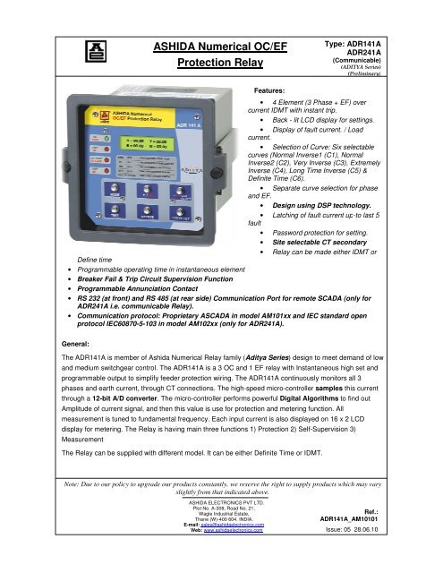
<strong>ASHIDA</strong> <strong>Numer</strong>ical <strong>OC</strong>/<strong>EF</strong><strong>Protection</strong> <strong>Relay</strong>Type: ADR141AADR241A(Communicable)(ADITYA Series)(Preliminary)Features:• 4 Element (3 Phase + <strong>EF</strong>) overcurrent IDMT with instant trip.• Back - lit LCD display for settings.• Display of fault current. / Loadcurrent.• Selection of Curve: Six selectablecurves (Normal Inverse1 (C1), NormalInverse2 (C2), Very Inverse (C3), ExtremelyInverse (C4), Long Time Inverse (C5) &Definite Time (C6).• Separate curve selection for phaseand <strong>EF</strong>.• Design using DSP technology.• Latching of fault current up-to last 5fault• Password protection for setting.• Site selectable CT secondary• <strong>Relay</strong> can be made either IDMT orDefine time• Programmable operating time in instantaneous element• Breaker Fail & Trip Circuit Supervision Function• Programmable Annunciation Contact• RS 232 (at front) and RS 485 (at rear side) Communication Port for remote SCADA (only forADR241A i.e. communicable <strong>Relay</strong>).• Communication protocol: Proprietary ASCADA in model AM101xx and IEC standard openprotocol IEC60870-5-103 in model AM102xx (only for ADR241A).General:The ADR141A is member of Ashida <strong>Numer</strong>ical <strong>Relay</strong> family (Aditya Series) ) design to meet demand of lowand medium switchgear control. The ADR141A is a 3 <strong>OC</strong> and 1 <strong>EF</strong> relay with Instantaneous high set andprogrammable output to simplify feeder protection wiring. The ADR141A continuously monitors all 3phases and earth current, through CT connections. The high-speed micro-controller samples this currentthrough a 12-bit A/D converter. . The micro-controller performs powerful Digital Algorithms to find outAmplitude of current signal, and then this value is use for protection and metering function. Allmeasurement is tuned to fundamental frequency. Each input current is also displayed on 16 x 2 LCDdisplay for metering. The <strong>Relay</strong> is having main three functions 1) <strong>Protection</strong> 2) Self-Supervision Supervision 3)MeasurementThe <strong>Relay</strong> can be supplied with different model. It can be either Definite Time or IDMT.Note: Due to our policy to upgrade our products constantly, we reserve the right to supply products which may varyslightly from that indicated above.<strong>ASHIDA</strong> ELECTRONICS PVT LTD.Plot No. A-308, Road No. 21,Wagle Industrial Estate,Thane (W)-400 604. INDIA.E-mail: sales@ashidaelectronics.comWeb: www.ashidaelectronics.comRef.:ADR141A_AM10101Issue: 05 28.06.10
Type: ADR141AADR241A(Communicable)(ADITYA Series)(Preliminary)1. <strong>Protection</strong> Functions:The ADR141A give maximum benefit/cost ratio. The ADR141A give all the advantage of numericalrelay at affordable cost. Following is summery of different protection functions provided by relay.ANSI IEC <strong>Protection</strong> Functions50 I >> Instantaneous Over current <strong>Protection</strong> (<strong>OC</strong>-Inst.)50N I E >> Instantaneous Earth Fault <strong>Protection</strong> (<strong>EF</strong>-Inst.)50,51 I>t, Ip Time Over current <strong>Protection</strong> (Phase) (<strong>OC</strong>-IDMT.)50N,51N I E >t, I EP Time Over current <strong>Protection</strong> (Earth) (<strong>EF</strong>-IDMT.)1.1. Over current / <strong>EF</strong> protection:The ADR141A has 4 sensing element 3 <strong>OC</strong> and 1 <strong>EF</strong>. The tripping current can be set from 10% to250% for phase and 10% to 250% for Earth fault in steps of 1% by Keys switch provided on frontpanel. The unit has got selection of IDMT characteristic of international IEC standard Very inverse /Extremely Inverse / Long Inverse and Standard inverse (both 3.0 sec and 1.3sec at 10 times). The unitalso has Time Multiplier Setting (TMS) from x0.01 to x1.0 for IDMT delay multiplication. Theinstantaneous tripping function is having range of 50% - 3000% for phase and 50% - 3000% for <strong>EF</strong>and can be set in steps of 50%. The high speeds CPU continuously monitor the all four current inputsand compare with IDMT as well as instantaneous setting. If anyone current is above instantaneoussetting the relay provides immediate trip command bypassing IDMT delay. If is input current is lessthan instantaneous setting but more than IDMT setting, CPU calculate IDMT delay as per selectedIDMT characteristic multiply it with TMS setting and provide trip command if fault is persist even afterthis time delay.All the settings are password protected to prevent unauthorised change.1.2. Extra Alarm Contact:Any <strong>Protection</strong> panel required extra contacts for provide visual ALARM and ANNUNCIATIONindication for operator. Also some status contacts for SCADA or remote indications. Usually separateelectromechanical relay used for contact multiplication of protection relay contacts. This added extrawiring and extra hardware. The ADR141A provide separate programmable ALARM contact for suchapplication. Maximum 4 nos. of extra contacts can be provided. These contacts can be programmedas followsNote: Due to our policy to upgrade our products constantly, we reserve the right to supply products which may varyslightly from that indicated above.<strong>ASHIDA</strong> ELECTRONICS PVT LTD.Plot No. A-308, Road No. 21,Wagle Industrial Estate,Thane (W)-400 604. INDIA.E-mail: sales@ashidaelectronics.comWeb: www.ashidaelectronics.comRef.:ADR141A_AM10101Issue: 05 28.06.10
Type: ADR141AADR241A(Communicable)(ADITYA Series)(Preliminary)ANN. TYPE 1 ANN. TYPE 2 ANN. TYPE 3 ANN. TYPE 4RELAY 1 <strong>OC</strong>1 <strong>OC</strong> HF HF COM. ALARMRELAY 2 <strong>OC</strong>2 <strong>OC</strong> IDMT IDMT PROTH.RELAY 3 <strong>OC</strong>3 <strong>EF</strong> HF PHASE PHASERELAY 4 <strong>EF</strong> <strong>EF</strong> IDMT <strong>EF</strong> <strong>EF</strong>2. Supervision Function:2.1 Self-supervision:The continuously keeping track on its internal hardware and the movement it detect any failure of anycomponent, it give message on LCD display, This feature is very useful to give pre information to avoidany mall - operation. In such situation it use some default setting and remain in protection mode.3. Measurement Function:In normal condition this display shows all settings. Via keyboard the display can be program to show theactual current flowing through the relay. If current excesses set value the relay gives trip command.The type of fault is displayed on LCD display. During the fault condition the relay measure the faultcurrent and store in non-volatile memory. The fault current can be read via keyboard on LCDdisplay Last 5 fault values along with tripping counter can be view via key-board. All settings aresave in electrically erasable read only memory and remain.4. Breaker Fail Function (BF or LBB)Normally after tripping current should be come Zero within 100 – 200ms time depend upon type of faultand breaker mechanism. After Fault <strong>Relay</strong> start one internal timer (settable from 0.05s to 0.8 s) If faultis not cleared during this time then relay declare as Breaker fail (LBB function)5. Status :Status input S1 and S2 are general purpose for SCADA application and S3 and S4 are dedicated forCB NC and NO used for trip circuit supervision.Note: Due to our policy to upgrade our products constantly, we reserve the right to supply products which may varyslightly from that indicated above.<strong>ASHIDA</strong> ELECTRONICS PVT LTD.Plot No. A-308, Road No. 21,Wagle Industrial Estate,Thane (W)-400 604. INDIA.E-mail: sales@ashidaelectronics.comWeb: www.ashidaelectronics.comRef.:ADR141A_AM10101Issue: 05 28.06.10
Type: ADR141AADR241A(Communicable)(ADITYA Series)(Preliminary)Ordering Information:The relay is available with nos. of different option. The option is specified by model no. It is userresponsibility to specify correct model no. while ordering.While Ordering Specify the following Information for ADR141A <strong>Relay</strong>D e f i n i t i o n o f M o d e l N o o f A d i t y a S e r i e s o f R e l a y sA M X X X – X X – X – X – X X – XReserved for Future UsePT Secondary0CT Secondary1 = 1 Amp.2 = 5 Amp.3 = 1 Amp. / 5 Amp. SelectableAuxiliary Supply01 = 18 – 52 V dc02 = 77 – 250 V dc03 = 110 VAC04 = 230 VAC05 = 60 V dc06 = 18 - 250 V dcAM XXX X X101 ( withASCADAProtocol forcommunication)102 ( withIEC60870-5-103Protocol forcommunication)Ordering information:3<strong>OC</strong> + 1<strong>EF</strong> <strong>Relay</strong>s01 <strong>Relay</strong> with site selectable CTs, Trip circuit supervision CSA – 150 3and breaker fail function. 4 extra Ann. Contacts and 4optically isolated status inputs ( 2nos for TSS )02 <strong>Relay</strong> with site selectable CTs in Draw out cabinet. CSA – 150D 301 <strong>Relay</strong> with site selectable CTs, Trip circuit supervision CSA – 150 3and breaker fail function. 4 extra Ann. Contacts and 4optically isolated status inputs ( 2nos for TSS )02 <strong>Relay</strong> with site selectable CTs in Draw out cabinet. CSA – 150D 3Note: communication protocols are only applicable for ADR241A relay models.A D R 1 4 1 A - A M - X X X - X X - X - X - X X - XExampleADR141A – AM-101-01-3-0-2-0Type: ADR141ABack Terminal Layout: With 4 Programmable extra contacts, Selectable CT TSS Logic.Cabinet Type: CSA-150 non DrawoutAuxiliary Supply: 77-250VdcCT sec: 1/5 Amp.Note: Due to our policy to upgrade our products constantly, we reserve the right to supply products which may varyslightly from that indicated above.<strong>ASHIDA</strong> ELECTRONICS PVT LTD.Plot No. A-308, Road No. 21,Wagle Industrial Estate,Thane (W)-400 604. INDIA.E-mail: sales@ashidaelectronics.comWeb: www.ashidaelectronics.comRef.:ADR141A_AM10101Issue: 05 28.06.10
Technical Specifications:Sr.No.SpecificationI. For Model AM101xx[ 3<strong>OC</strong> + 1<strong>EF</strong> relay ]ParticularsType: ADR141AADR241A(Communicable)(ADITYA Series)(Preliminary)Inputs : Suitable for CT secondary 1.0 Amp or 5.0 Amp.(Selectable)<strong>Protection</strong> <strong>Relay</strong> SettingRangeOutput contacts: Setting For phase 10% - 250 %For <strong>EF</strong> 10% - 250%: Operating Time Normal Inverse 1 (C1)Normal Inverse 2 (C2)Very Inverse (C3)Extremely Inverse (C4)Long Time Inverse (C5)Definite Tme (C6) 00(Inst) – 99.9Sec: Inst. Setting For phase 50% - 3000%. or bypass In steps of 50%For <strong>EF</strong> 50% - 3000% or bypass In steps of 50%: Inst Operating Time Inst = < 30ms and additional adjustable softwaredelay of 00 – 2.0Sec in steps of 10ms.: ModelAM10101xxxxx&AM10201xxxxx1) 2 NO Trip duty contact for Alarm and Trip2) 4 NO ANN. Duty contacts ( Programmable): Model 2 NO Trip duty contact for Alarm and TripAM10102xxxxx&AM10202xxxxxII. Pickup Current : Within 1.1 times of set current value.III. Resetting Current : 90% of set value.IV. Time Accuracy : Within class 5 As per IS: 3231.V. Burden on CTs : Less than 0.2VA.VI. Aux. Supply : 18 – 52VDC or 77 – 250VDC. To be specified while ordering.VII. Burden on Aux. Supply : Less than 10VA on any supply.VIII. Contact Rating Trip Duty : Make and carry for 3sec. – 7500VA with max. 30A & 660VAC/DCIX.ON / Error: Make and carry for continuous – 1250VA with max. 5A & 660VAC/DC: Break AC – 1250 VA DC – 100 W resistive 50W inductive.Operational Indicators (Flags): Green LED indicates <strong>Relay</strong> OK: Red LED indicates Problem in relay Hardware.Note: Due to our policy to upgrade our products constantly, we reserve the right to supply products which may varyslightly from that indicated above.<strong>ASHIDA</strong> ELECTRONICS PVT LTD.Plot No. A-308, Road No. 21,Wagle Industrial Estate,Thane (W)-400 604. INDIA.E-mail: sales@ashidaelectronics.comWeb: www.ashidaelectronics.comRef.:ADR141A_AM10101Issue: 05 28.06.10
PKP / HFType: ADR141AADR241A(Communicable)(ADITYA Series)(Preliminary): Green LED indicates relay Pickup.: Red LED indicates relay operated at HF.<strong>OC</strong> Fault / <strong>EF</strong> FaultTRIP / BF: Green LED indicates the relay tripped by <strong>OC</strong>, Hand Reset (HR) Type: Red LED indicates the relay tripped by <strong>EF</strong>, Hand Reset (HR) Type: Green LED Indicates that Trip pulse is being executed. SR type whenTRIP contact selected as SR and HR type when TRIP contact selected asHR. When BYPASS P.B. is pressed, actual trip is not executed.: Red LED indicates BF operated. SR type when BF contact selected as SRand HR type when BF contact selected as HR.X. Thermal Withstand Capacity : x40 times the normal current for 3sec.: x2 ContinuousXI. High Voltage Test : IEC 60255-5XII.Impulse Voltage Test (allcircuit class – III): Except DC Voltage – 2.0 kV (RMS), 50Hz: Only DC voltage - 2.8 kV DC: Between Open contact of TRIP / CLOSE 1.5kV (RSM) 50Hz: Between Open contact of ALARM – 1kV (RSM) 50Hz: IEC60255-5: 5kV (peak) 1.2 / 50us, 0.5 J, 3 positive and 3 negative impulse at interval of5 secXIII. High Frequency test : IEC 60255-22-1, Class III: 2.5 kV (peak) 1MHz , τ = 15µs 400 surges / s duration 2 sXIV. Electro static Discharge : IEC 60255-22-2 Class III and IEC 61000-4-2 class IIIXV.XVI.Irradiation with radiofrequency field, pulsemodulated,Fast transientinterference/bursts: 4kV/6kV contact discharge, 8kV air discharge, both polarities 150pF, Ri330 Ω: IEC 60255-22-3 and IEC 61000-4-2 class III: 10V/m; 80 to 1000MHz; 80%; 1kHz AM: IEC 60255-22-3 and IEC 61000-4-3, class III: 4kV; 5/50ns; 5kHz burst duration = 15ms;: Repetition rate 300ms; Both polarities; Ri = 50Ω; duration 1 min.XVII. Shock Test : IEC 60255-21-2 class 1: Semi-Sinusoidal: 5g acceleration, duration 11ms,: Each 3 shocks in both direction of the 3 axesXVIII. Vibration Test : IEC 60255-21-1 class 1 / IEC 60068-2-6: Sinusoidal 10 to 60Hz ±0.035 mm: Amplitude, 60 to 150Hz, 0.5g acceleration: Sweep rate 1 octave/min; 20 cycle in 3 orthogonalXIX. Seismic Test : IEC 60255-21-3Note: Due to our policy to upgrade our products constantly, we reserve the right to supply products which may varyslightly from that indicated above.<strong>ASHIDA</strong> ELECTRONICS PVT LTD.Plot No. A-308, Road No. 21,Wagle Industrial Estate,Thane (W)-400 604. INDIA.E-mail: sales@ashidaelectronics.comWeb: www.ashidaelectronics.comRef.:ADR141A_AM10101Issue: 05 28.06.10
Issue No.(Revision)DateDescription /Changes01 28.08.09 Original Revision02 01.11.09 Communicable Model ADR241A added03 01.12.09 Photograph of the relay Modified04 09.12.09 Settings ChangedType: ADR141AADR241A(Communicable)(ADITYA Series)(Preliminary)Note: Due to our policy to upgrade our products constantly, we reserve the right to supply products which may varyslightly from that indicated above.<strong>ASHIDA</strong> ELECTRONICS PVT LTD.Plot No. A-308, Road No. 21,Wagle Industrial Estate,Thane (W)-400 604. INDIA.E-mail: sales@ashidaelectronics.comWeb: www.ashidaelectronics.comRef.:ADR141A_AM10101Issue: 05 28.06.10