Ferrobal Rod ends, Hydraulic rod ends, Spherical plain bearings ...
Ferrobal Rod ends, Hydraulic rod ends, Spherical plain bearings ...
Ferrobal Rod ends, Hydraulic rod ends, Spherical plain bearings ...

Create successful ePaper yourself
Turn your PDF publications into a flip-book with our unique Google optimized e-Paper software.
The<br />
Standard<br />
<strong>Rod</strong> end...<br />
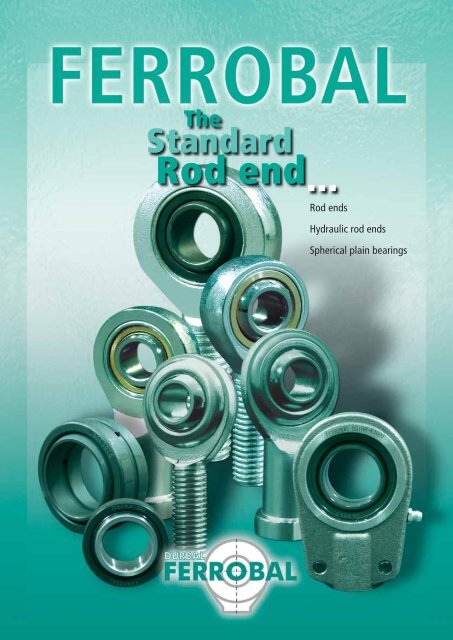
<strong>Rod</strong> <strong>ends</strong><br />
<strong>Hydraulic</strong> <strong>rod</strong> <strong>ends</strong><br />
<strong>Spherical</strong> <strong>plain</strong> <strong>bearings</strong>
DURBAL Vertriebsgesellschaft mbH<br />
FERROBAL is the registered trademark for the<br />
standard series of <strong>rod</strong> <strong>ends</strong>, <strong>bearings</strong> and hydraulic<br />
<strong>rod</strong> <strong>ends</strong> of DURBAL Vertriebsgesellschaft<br />
mbH.<br />
FERROBAL ® <strong>rod</strong> <strong>ends</strong> and <strong>bearings</strong> are standardized<br />
machine components designed for<br />
the transmission of static and dynamic loads<br />
in combination with swivelling, tilting or rotating<br />
movements.<br />
The large assortment shows all common characteristics<br />
and encloses the following spherical<br />
bearing types:<br />
• steel / steel<br />
• stee / bronze<br />
• stee / bronze-PTFE composite.<br />
FERROBAL ® standard p<strong>rod</strong>ucts are p<strong>rod</strong>uced<br />
2<br />
according to DIN ISO standards and are<br />
characterized by high precision and reliability<br />
as well as an outstanding price - performance<br />
ratio.<br />
FERROBAL standard p<strong>rod</strong>ucts and DURBAL<br />
heavy-duty <strong>rod</strong> <strong>ends</strong> are the assortment of<br />
DURBAL Vertriebsgesellschaft mbH.<br />
Quality objectives of DURBAL Vertriebsgesellschaft<br />
mbH:<br />
• assurance of a constantly high p<strong>rod</strong>uct<br />
quality<br />
• continuous monitoring and adjustment<br />
of the p<strong>rod</strong>uct characteristics to customers<br />
requirements<br />
• utilisation of efficient methods of p<strong>rod</strong>uction<br />
to minimize manufacturing costs.<br />
• permanent stock availability of the<br />
DURBAL and FERROBAL assortment.<br />
• customer orientated service.<br />
The work flow at sales of the FERROBAL and<br />
DURBAL assortment is systematically controlled<br />
in accordance with the guidelines of DIN<br />
EN ISO 9001: 2000. Thereby DURBAL Group<br />
can revert to an experience of over 65 years in<br />
p<strong>rod</strong>uction and sales of <strong>rod</strong> <strong>ends</strong> and machine<br />
components.<br />
In terms of technical and economical progress<br />
the catalogue data is subject to changes.<br />
Our experienced staff members will<br />
always be available to answer any<br />
queries you may have.<br />
DURBAL Vertriebsgesellschaft mbH<br />
Verrenberger Weg 2-2A<br />
D - 74613 Öhringen<br />
Postfach 1440<br />
D - 74604 Öhringen<br />
Telefon +49 7941 - 94 60 - 0<br />
Telefax +49 7941 - 94 60 - 90<br />
Sales division Germany:<br />
Telefon +49 7941 - 94 60 - 31<br />
Export:<br />
Telefon +49 7941 - 94 60 - 33<br />
Technical division:<br />
Telefon +49 7941 - 94 60 - 0<br />
Email:<br />
info@durbal.de<br />
www:<br />
www.durbal.de<br />
www.ferrobal.de
Table of contents <strong>rod</strong> <strong>ends</strong> <strong>bearings</strong><br />
Male thread<br />
Sealing<br />
Maintenance free<br />
Stainless Steel<br />
Clamping<br />
thread<br />
Female<br />
Type<br />
Sliding<br />
combination Size DIN ISO Description Page<br />
<strong>Rod</strong> <strong>ends</strong><br />
DSI...T/K steel / bronze-PTFE X X 5 - 50 ISO 12240-4 K 12<br />
DSA...T/K steel / bronze-PTFE X X 5 - 50 ISO 12240-4 K 13<br />
steel / bronze-PTFE X X X 5 - 30 ISO 12240-4 K stainless steel 14<br />
DSSA...T/K steel / bronze-PTFE X X X 5 - 30 ISO 12240-4 K stainless steel 15<br />
DSI... P<br />
steel / bronze-PTFE X X 5 - 25 ISO 12240-4 K 16<br />
DSA... P<br />
steel / bronze-PTFE X X 5 - 25 ISO 12240-4 K 17<br />
DGIR...UK steel / bronze-PTFE X X 6 - 30 ISO 12240-4 E 18<br />
DGIR...UK-2RS steel / bronze-PTFE X X X 17 - 80 ISO 12240-4 E 18<br />
DGAR...UK steel / bronze-PTFE X X 6 - 30 ISO 12240-4 E 19<br />
DGAR...UK-2RS steel / bronze-PTFE X X X 17 - 80 ISO 12240-4 E 19<br />
DPHS steel / bronze X 5 - 30 ISO 12240-4 K 20<br />
DPOS steel / bronze X 5 - 30 ISO 12240-4 K 21<br />
DSI...E/ES steel / steel X 6 - 80 ISO 12240-4 E 22<br />
DSI...ES-2RS steel / steel X X 15 - 80 ISO 12240-4 E 22<br />
DSA...E/ES steel / steel X 6 - 80 ISO 12240-4 E 23<br />
DSA...ES-2RS steel / steel X X 15 - 80 ISO 12240-4 E 23<br />
DSIZP...S steel / bronze X - 1" (ISO 12240-4 K) in inches 24<br />
DSAZP...S steel / bronze X - 1" (ISO 12240-4 K) in inches 25<br />
DSIZJ...S steel / steel X - 3/4" (ISO 12240-4 K) in inches 26<br />
DSAZJ...S steel / steel X - 3/4" (ISO 12240-4 K) in inches 27<br />
Mountings 50<br />
<strong>Hydraulic</strong> <strong>rod</strong> <strong>ends</strong><br />
DGIHR-K...DO steel / steel X X 20 - 120 28<br />
DGIHR...DO steel / steel X 20 - 120 without clamping 29<br />
DGIHN-K...LO steel / steel X X 12 - 125 similar to DIN 24338 30<br />
DGIHO-K...DO steel / steel X X 12 - 100 similar to DIN 24555 31<br />
DGF...DO steel / steel 20 - 120 32<br />
DGK...DO steel / steel 10 - 80 ISO 12240-4 E Form S 33<br />
Subject to change without notice. 3
Table of content spherical <strong>plain</strong> <strong>bearings</strong><br />
Type<br />
Sliding<br />
combination<br />
Size<br />
<strong>Spherical</strong> <strong>plain</strong> bearing<br />
DIN ISO Description Page<br />
DG...PW steel / bronze-PTFE X 5 - 50 ISO 12240-1 K 34<br />
4<br />
Sealing<br />
Maintenance free<br />
Stainless Steel<br />
DS...PW steel / bronze-PTFE X 5 - 30 similar to ISO 12240-1 K 35<br />
DGE...UK steel / bronze-PTFE X 6 - 30 ISO 12240-1 E 36<br />
DSGE...UK steel / bronze-PTFE X X 6 - 30 ISO 12240-1 E stainless steel 37<br />
DGE...UK-2RS steel / bronze-PTFE X X 15 - 120 ISO 12240-1 E 38<br />
DGE...FW steel / steel-PTFE X 6 - 30 ISO 12240-1 G 39<br />
DSGE...FW steel / steel-PTFE X X 6 - 30 ISO 12240-1 G stainless steel 40<br />
DGE...FW-2RS steel / steel-PTFE X X 15 - 100 ISO 12240-1 G 41<br />
DG...PB steel / bronze 5 - 50 ISO 12240-1 K 42<br />
DS...PB steel / bronze 5 - 30 similar to ISO 12240-1 K 43<br />
DGEBK...S steel / bronze-Alu 5 - 30 similar to ISO 12240-1 K 44<br />
DGEBJ...S steel / steel 5 - 30 ISO 12240-1 K 45<br />
DGE...E/ES steel / steel 6 - 160 ISO 12240-1 E 46<br />
DGE...ES-2RS steel / steel X 6 - 160 ISO 12240-1 E 46<br />
DGEZ...E/ES steel / steel 1/2" - 4 3/4 " (ISO 12240-1 E) in inches 47<br />
DGEZ...ES-2RS steel / steel X 1" - 4 3/4 " (ISO 12240-1 E) in inches 47<br />
DGEG...E/ES steel / steel 6 - 120 ISO 12240-1 G similar to type DGE...ES 48<br />
DGEG...ES-2RS steel / steel X 15 - 120 similar to ISO 12240-1 G<br />
DGE...LO steel / steel 20 - 80 ISO 12240-1 W<br />
DGE...HO-2RS steel / steel X 20 - 80 similar to ISO 12240-1 W<br />
similar to type<br />
DGE...ES-2RS<br />
with cylindrical extension<br />
on both sides<br />
with cylindrical extension<br />
on both sides<br />
48<br />
49<br />
49<br />
Subject to change without notice.
Selection criteria of FERROBAL ® <strong>rod</strong> <strong>ends</strong> and <strong>bearings</strong><br />
The specific application conditions and the installation settings of <strong>rod</strong> <strong>ends</strong> and <strong>bearings</strong> are varying in practical use and therefore cannot be<br />
generalised in a catalogue.<br />
The specific application conditions are<br />
The installation setting is determined by:<br />
affected by:<br />
Factor and kind of affecting load:<br />
• constant / alternating<br />
• static / dynamic<br />
• axial / radial<br />
Angle of tilt<br />
Swivelling angle<br />
Temperature<br />
Environment conditions<br />
• dust<br />
• dirt<br />
• humidity<br />
(This list may not be complete)<br />
With the details given in the catalogue the user will be able to roughly determine the <strong>rod</strong> <strong>ends</strong> and <strong>bearings</strong> that will be adequate for the<br />
concrete application.<br />
Static load Co<br />
The maximal admissible load of a FERROBAL ® <strong>rod</strong> end or bearing is specified by<br />
the static load rating Co hat is indicated in the catalogue.<br />
The static load rating Co of a <strong>plain</strong> bearing corresponds to the static radial load that does<br />
not yet cause a lasting deformation at the weakest housing section of the <strong>rod</strong> end or bearing<br />
during standstill at room temperature.<br />
Temperature - range of application<br />
Non-maintenance-free: -40°C to +300°C<br />
(from +150°C with restriction of the loading capacity)<br />
Maintenance free: -40°C to +130°C<br />
In all cases the user has to coordinate the theoretical selection criteria with the<br />
concrete installation situation and check the suitability of the <strong>rod</strong> end respectively<br />
bearing. In this context the user has to define sufficient security factors and mainten<br />
ance intervals.<br />
Whenever the load is defined at the upper limit of the load rating<br />
DURBAL Vertriebsgesellschaft is recommending to use<br />
DURBAL ® heavy duty <strong>rod</strong> <strong>ends</strong>.<br />
Our specialists will be pleased to provide advice.<br />
Selection criteria<br />
The maximal dimension of the machinery element.<br />
The existing adapter sizes for threads or other connections.<br />
The lubrication and maintenance situation.<br />
Lubrication:<br />
• wanted<br />
• not wanted<br />
• central lubrication<br />
• decentralised lubrication<br />
5
Tolerances<br />
FERROBAL ® <strong>rod</strong> <strong>ends</strong><br />
Symbol<br />
d = Bore diameter of bearing<br />
Δdmp = Single plane mean bore diameter deviation<br />
Vdp = Bore diameter variation in a single radial plane<br />
Vdmp = Variation of mean bore diameter<br />
= Deviation of a single width of the inner ring<br />
Δ Bs<br />
Thread:<br />
Metric measurements: Measurements in inches:<br />
Female thread DIN ISO 965-1 6H Female thread UNF - 3B<br />
Male thread nach DIN ISO 965-1 6g Male thread UNF - 3A<br />
Inner ring:<br />
Type:<br />
DSI...E + ES<br />
DSI...ES-2RS<br />
DSA...E + ES<br />
DSA...ES-2RS<br />
DGIR...UK<br />
DGIR...UK-2RS<br />
DGAR...UK<br />
DGAR...UK-2RS<br />
DGK...DO<br />
DGF...DO<br />
DGIHR...DO<br />
DGIHR-K...DO<br />
DGIHN-K...LO<br />
Type:<br />
DPHS<br />
DPOS<br />
DSIZP...S<br />
DSAZP...S<br />
DSIZJ...S<br />
DSAZJ...S<br />
DGIHO-K...DO<br />
Type:<br />
DSI...T/K<br />
DSA...T/K<br />
DSI...PK<br />
DSA...PK<br />
DSSI...T/K<br />
DSSA...T/K<br />
Tolerances of all ather measurements according to DIN ISO 12240-4.<br />
6<br />
Inner ring<br />
d<br />
over<br />
incl.<br />
mm<br />
-<br />
10<br />
10<br />
18<br />
18<br />
30<br />
30<br />
50<br />
50<br />
80<br />
80<br />
120<br />
120<br />
150<br />
Δdmp<br />
Vdp<br />
Vdmp<br />
Δ Bs<br />
μm<br />
μm<br />
μm<br />
μm<br />
0 0 0 0 0 0 0<br />
-8 -8 -10 -12 -15 -20 -25<br />
8 8 10 12 15 20 25<br />
6 6 8 9 11 15 19<br />
0 0 0 0 0 0 0<br />
-120 -120 -120 -120 -120 -120 -120<br />
Innenring<br />
d<br />
über<br />
bis<br />
mm<br />
-<br />
6<br />
6<br />
10<br />
10<br />
18<br />
18<br />
30<br />
30<br />
50<br />
50<br />
80<br />
80<br />
120<br />
Δdmp<br />
μm<br />
+12<br />
0<br />
+15<br />
0<br />
+18<br />
0<br />
+21<br />
0<br />
+25<br />
0<br />
+30<br />
0<br />
+35<br />
0<br />
Δ Bs<br />
μm<br />
0 0 0 0 0 0 0<br />
-120 -120 -120 -120 -120 -120 -120<br />
Innenring<br />
d<br />
über<br />
bis<br />
mm<br />
-<br />
6<br />
6<br />
10<br />
10<br />
12<br />
12<br />
18<br />
18<br />
30<br />
30<br />
50<br />
Δdmp<br />
μm<br />
+12<br />
0<br />
+15<br />
0<br />
+18<br />
0<br />
+18<br />
0<br />
+21<br />
0<br />
+25<br />
0<br />
Δ Bs<br />
μm<br />
0 0 0 0 0 0<br />
-120 -120 -120 -120 -120 -120
FERROBAL ® spherical <strong>plain</strong> <strong>bearings</strong><br />
Symbol<br />
d = Bore diameter of bearing<br />
Δdmp = Single plane mean bore diameter deviation<br />
Vdp = Bore diameter variation in a single radial plane<br />
Vdmp = Variation of mean bore diameter<br />
Δ Bs = Deviation of a single width of the inner ring<br />
Type:<br />
DGE...E + ES<br />
DGE...ES-2RS<br />
DGEZ...ES<br />
DGEZ...ES-2RS<br />
DGEG...E + ES<br />
DGEG...ES-2RS<br />
DGE...UK<br />
DGE...UK-2RS<br />
DGE...FW<br />
DGE...FW-2RS<br />
DGE...HO-2RS<br />
DSGE...UK<br />
DSGE...FW<br />
Type:<br />
DGE...LO<br />
Type:<br />
DGEBK...S<br />
DGEBJ...S<br />
DG...PW<br />
DG...PB<br />
DS...PW<br />
DS...PB<br />
Tolerances<br />
D = Outside diameter of bearing<br />
ΔDmp = Single plane mean outside diameter deviation<br />
VDp = Variation of outside diameter in a single radial plane<br />
VDmp = Variation of mean outside diameter<br />
Δ Cs = Deviation of a single width of the outer ring<br />
Inner ring<br />
d<br />
over<br />
incl.<br />
mm<br />
-<br />
10<br />
10<br />
18<br />
18<br />
30<br />
30<br />
50<br />
50<br />
80<br />
80<br />
120<br />
120<br />
150<br />
Δdmp<br />
Vdp<br />
μm<br />
μm<br />
0<br />
-8<br />
8<br />
0<br />
-8<br />
8<br />
0<br />
-10<br />
10<br />
0<br />
-12<br />
12<br />
0<br />
-15<br />
15<br />
0<br />
-20<br />
20<br />
0<br />
-25<br />
25<br />
Vdmp<br />
μm 6 6 8 9 11 15 19<br />
Δ Bs<br />
μm 0<br />
-120<br />
0<br />
-120<br />
0<br />
-120<br />
0<br />
-120<br />
0<br />
-120<br />
0<br />
-120<br />
0<br />
-120<br />
Outer ring<br />
D<br />
over<br />
incl.<br />
mm<br />
10<br />
18<br />
18<br />
30<br />
30<br />
50<br />
50<br />
80<br />
80<br />
120<br />
120<br />
150<br />
150<br />
180<br />
180<br />
250<br />
ΔDmp<br />
VDp<br />
μm<br />
μm<br />
0<br />
-8<br />
10<br />
0<br />
-9<br />
12<br />
0<br />
-11<br />
15<br />
0<br />
-13<br />
17<br />
0<br />
-15<br />
20<br />
0<br />
-18<br />
24<br />
0<br />
-25<br />
33<br />
0<br />
-30<br />
40<br />
VDmp<br />
μm 6 7 8 10 11 14 19 23<br />
Δ Cs<br />
μm<br />
0<br />
-240<br />
0<br />
-240<br />
0<br />
-240<br />
0<br />
-240<br />
0<br />
-240<br />
0<br />
-240<br />
0<br />
-240<br />
0<br />
-240<br />
Inner ring<br />
d<br />
over<br />
incl.<br />
mm<br />
10<br />
18<br />
18<br />
30<br />
30<br />
50<br />
50<br />
80<br />
Δdmp<br />
Vdp<br />
μm<br />
μm<br />
+18<br />
0<br />
18<br />
+21<br />
0<br />
21<br />
+25<br />
0<br />
25<br />
+30<br />
0<br />
30<br />
Vdmp<br />
μm 14 16 19 22<br />
Δ Bs<br />
μm<br />
0<br />
-120<br />
0<br />
-120<br />
0<br />
-120<br />
0<br />
-120<br />
Outer ring: Tolerances of the outer rings similar to type DGE...ES.<br />
Inner ring<br />
d<br />
over<br />
incl.<br />
mm<br />
-<br />
6<br />
6<br />
10<br />
10<br />
18<br />
18<br />
30<br />
Δdmp<br />
μm +12<br />
0<br />
+15<br />
0<br />
+18<br />
0<br />
+21<br />
0<br />
Δ Bs<br />
μm<br />
0<br />
-120<br />
0<br />
-120<br />
0<br />
-120<br />
0<br />
-120<br />
Outer ring<br />
D<br />
over<br />
incl.<br />
mm<br />
10<br />
18<br />
18<br />
30<br />
30<br />
50<br />
50<br />
60<br />
ΔDmp<br />
μm<br />
0<br />
-11<br />
0<br />
-13<br />
0<br />
-16<br />
0<br />
-19<br />
Δ Cs<br />
μm<br />
0<br />
-240<br />
0<br />
-240<br />
0<br />
-240<br />
0<br />
-240<br />
7
Fit tolerances<br />
Recommended fit for radial <strong>plain</strong> <strong>bearings</strong><br />
Shaft fit type of bearing<br />
Lubrication required maintenance free<br />
Loads if all kinds, clearence<br />
or transition fit<br />
Loads of all kinds,<br />
interferenz fit<br />
Recommended roughness of fitting surface<br />
Recommended shape and position tolerance of fitting surface<br />
8<br />
f8, h6, h7 g6,h6<br />
m6, n6 k6<br />
Housing fit type of bearing<br />
Lubrication required maintenance free<br />
Low loads clearence<br />
or transition fit<br />
Heavy loads,<br />
interferenz fit<br />
Light alloy housings<br />
d / D<br />
Cylindricity<br />
Side beat of<br />
round circuity<br />
H6, H7 H7<br />
J7, M7 K7<br />
N7 M7<br />
Fitting surface incl. d/D 80 over d/D 80<br />
shaft surface<br />
bore surface of housing<br />
side of shaft shoulder, washer,<br />
housing bore shoulder<br />
Ra < 1,25 Ra < 2,00<br />
Ra < 1,60 Ra < 2,50<br />
Ra < 2,00 Ra < 2,50<br />
over<br />
incl.<br />
mm<br />
-<br />
6<br />
6<br />
10<br />
10<br />
18<br />
18<br />
30<br />
30<br />
50<br />
50<br />
80<br />
80<br />
120<br />
120<br />
150<br />
150<br />
180<br />
180<br />
250<br />
shaft Ø < μm 4 4 5 6 7 8 10 12 12 14<br />
housing bore Ø < μm - 4 5 6 7 8 10 12 12 14<br />
shaft shoulder < μm 8 9 11 13 16 19 22 25 25 29<br />
housing bore shoulder Ø < μm - 9 11 13 16 19 22 25 25 29<br />
Subject to change without notice.
Radial clearance of FERROBAL ® spherical <strong>plain</strong> <strong>bearings</strong><br />
Non-maintenance-free spherical <strong>plain</strong> <strong>bearings</strong><br />
Type:<br />
DGE...E + ES<br />
DGE...ES-2RS<br />
DGE...HO-2RS<br />
DGE...LO<br />
DG...PB<br />
DS...PB<br />
Type:<br />
DGEG...ES<br />
DGEG...ES-2RS<br />
Type:<br />
DGEZ...ES<br />
DGEZ...ES-2RS<br />
Type:<br />
DGEBK...S<br />
DGEBJ...S<br />
Maintenance-free spherical <strong>plain</strong> <strong>bearings</strong><br />
Type:<br />
DG...PW<br />
DS...PW<br />
DGE...UK<br />
DGE...FW<br />
DSGE...UK<br />
DSGE...FW<br />
Type:<br />
DGE...UK-2RS<br />
Type:<br />
DGE...FW-2RS<br />
Radial clearance<br />
d<br />
over<br />
incl.<br />
mm<br />
-<br />
12<br />
12<br />
20<br />
20<br />
35<br />
35<br />
60<br />
60<br />
90<br />
90<br />
140<br />
group 2 μm 8<br />
32<br />
10<br />
40<br />
12<br />
50<br />
15<br />
60<br />
18<br />
72<br />
18<br />
85<br />
group N μm 32<br />
68<br />
40<br />
82<br />
50<br />
100<br />
60<br />
120<br />
72<br />
142<br />
85<br />
165<br />
group 3 μm<br />
68<br />
104<br />
82<br />
124<br />
100<br />
150<br />
120<br />
180<br />
142<br />
212<br />
165<br />
245<br />
d<br />
over<br />
incl.<br />
mm<br />
-<br />
10<br />
10<br />
17<br />
17<br />
30<br />
30<br />
50<br />
50<br />
80<br />
80<br />
120<br />
group 2 μm 8<br />
32<br />
10<br />
40<br />
12<br />
50<br />
15<br />
60<br />
18<br />
72<br />
18<br />
85<br />
group N μm 32<br />
68<br />
40<br />
82<br />
50<br />
100<br />
60<br />
120<br />
72<br />
142<br />
85<br />
165<br />
group 3 μm<br />
68<br />
104<br />
82<br />
124<br />
100<br />
150<br />
120<br />
180<br />
142<br />
212<br />
165<br />
245<br />
d<br />
over<br />
incl.<br />
mm<br />
-<br />
5/8 "<br />
5/8 "<br />
2 "<br />
2 "<br />
3 "<br />
3 "<br />
6 "<br />
group N μm 50<br />
150<br />
80<br />
180<br />
100<br />
200<br />
130<br />
230<br />
d<br />
over<br />
incl.<br />
mm<br />
-<br />
30<br />
group N μm<br />
0<br />
35<br />
d<br />
over<br />
incl.<br />
mm<br />
-<br />
12<br />
12<br />
20<br />
20<br />
30<br />
group N μm<br />
4<br />
28<br />
5<br />
35<br />
6<br />
44<br />
d<br />
over<br />
incl.<br />
mm<br />
2<br />
20<br />
20<br />
35<br />
35<br />
60<br />
60<br />
90<br />
90<br />
140<br />
group N μm 0<br />
40<br />
0<br />
50<br />
0<br />
60<br />
0<br />
72<br />
0<br />
85<br />
d<br />
over<br />
incl.<br />
mm<br />
-<br />
30<br />
30<br />
50<br />
50<br />
80<br />
80<br />
120<br />
group N μm<br />
0<br />
50<br />
0<br />
60<br />
0<br />
72<br />
0<br />
85<br />
Subject to change without notice. 9
Radial clearance<br />
Radial clearance of FERROBAL ® <strong>rod</strong> <strong>ends</strong><br />
Non-maintenance-free <strong>rod</strong> <strong>ends</strong><br />
Type:<br />
DSI...E + ES<br />
DSI...ES-2RS<br />
DSA...E + ES<br />
DSA...ES-2RS<br />
DGIHR...DO<br />
DGIHR-K...DO<br />
DGK...DO<br />
DGF...DO<br />
DGIHR-K...LO<br />
DGIHO-K...DO<br />
Type:<br />
DPHS<br />
DPOS<br />
DSIZP...S<br />
DSAZP...S<br />
Type:<br />
DSIZJ...<br />
DSAZJ...<br />
Maintenance-free <strong>rod</strong> <strong>ends</strong><br />
Type:<br />
DSI...T/K<br />
DSA...T/K<br />
DSI...PK<br />
DSA...PK<br />
Type:<br />
DGIR...UK<br />
DGIR...UK-2RS<br />
DGAR...UK<br />
DGAR...UK-2RS<br />
10<br />
d<br />
over<br />
incl.<br />
mm<br />
-<br />
12<br />
12<br />
20<br />
20<br />
35<br />
35<br />
60<br />
60<br />
80<br />
group N μm 0<br />
68<br />
0<br />
82<br />
0<br />
10<br />
0<br />
120<br />
0<br />
142<br />
d<br />
over<br />
incl.<br />
mm<br />
-<br />
30<br />
group N μm<br />
0<br />
35<br />
d<br />
over<br />
incl.<br />
mm<br />
-<br />
8<br />
8<br />
14<br />
14<br />
20<br />
20<br />
35<br />
35<br />
50<br />
group N μm 10<br />
30<br />
15<br />
60<br />
40<br />
80<br />
50<br />
90<br />
60<br />
110<br />
d<br />
over<br />
incl.<br />
mm<br />
-<br />
12<br />
12<br />
20<br />
20<br />
30<br />
group N μm<br />
0<br />
32<br />
0<br />
40<br />
0<br />
50<br />
d<br />
over<br />
incl.<br />
mm<br />
-<br />
12<br />
12<br />
20<br />
20<br />
35<br />
35<br />
60<br />
60<br />
80<br />
group N μm 0<br />
32<br />
0<br />
40<br />
0<br />
50<br />
0<br />
60<br />
0<br />
72<br />
Subject to change without notice.
DSI...T/K<br />
female thread;<br />
maintenance free,<br />
according to<br />
DIN ISO 12240-4,<br />
series K<br />
Description: DIN ISO <strong>rod</strong> end K series. Made of<br />
spherical <strong>plain</strong> bearing DG…PW pressed into <strong>rod</strong> end<br />
body. Sliding combination steel / bronze-PTFE composite.<br />
<strong>Rod</strong> end body:<br />
surface zinc plated<br />
order number measurement [mm]<br />
Sliding combination:<br />
steel / bronze-PTFE composite<br />
Inner ring:<br />
bearing steel, hardened, ground and<br />
spherical surface chromium plated<br />
Outer ring:<br />
brass body pressed around, outer race<br />
lined with bronze-PTFE composite<br />
Lubrication:<br />
maintenance free<br />
right hand thread left hand thread d G B C1 d2 d3 d4<br />
DSI 5 T/K DSIL 5 T/K 5 M 5 8 6,00 18 8,5 11<br />
DSI 6 T/K DSIL 6 T/K 6 M 6 9 6,75 20 10,0 13<br />
DSI 8 T/K DSIL 8 T/K 8 M 8 12 9,00 24 12,5 16<br />
DSI 10 T/K DSIL 10 T/K 10 M 10 14 10,50 28 15,0 19<br />
DSI 10 T/K M 10 X 1,25 DSIL 10 T/K M 10 X 1,25 10 M 10 x 1,25 14 10,50 28 15,0 19<br />
DSI 12 T/K DSIL 12 T/K 12 M 12 16 12,00 32 17,5 22<br />
DSI 12 T/K M 12 X 1,25 DSIL 12 T/K M 12 X 1,25 12 M 12 x 1,25 16 12,00 32 17,5 22<br />
DSI 14 T/K DSIL 14 T/K 14 M 14 19 13,50 36 20,0 25<br />
DSI 14 T/K M 14 X 1,5 DSIL 14 T/K M 14 X 1,5 14 M 14 x 1,5 19 13,50 36 20,0 25<br />
DSI 16 T/K DSIL 16 T/K 16 M 16 21 15,00 42 22,0 27<br />
DSI 16 T/K M 16 X 1,5 DSIL 16 T/K M 16 X 1,5 16 M 16 x 1,5 21 15,00 42 22,0 27<br />
DSI 18 T/K DSIL 18 T/K 18 M 18 x 1,5 23 16,50 44 25,0 31<br />
DSI 20 T/K DSIL 20 T/K 20 M 20 x 1,5 25 18,00 50 27,5 34<br />
DSI 22 T/K DSIL 22 T/K 22 M 22 x 1,5 28 20,00 54 30,0 38<br />
DSI 25 T/K DSIL 25 T/K 25 M 24 x 2 31 22,00 60 33,5 42<br />
DSI 28 T/K DSIL 28 T/K 28 M 27 x 2 35 24,00 66 37,0 46<br />
DSI 30 T/K DSIL 30 T/K 30 M 30 x 2 37 25,00 70 40,0 50<br />
DSI 30 T/K M 27 X 2 DSIL 30 T/K M 27 X 2 30 M 27 x 2 37 25,00 70 40,0 50<br />
DSI 35 T/K DSIL 35 T/K 35 M 36 x 2 43 28,00 81 46,0 58<br />
DSI 40 T/K DSIL 40 T/K 40 M 42 x 2 49 33,00 91 53,0 65<br />
DSI 50 T/K DSIL 50 T/K 50 M 48 x 2 60 45,00 117 65,0 75<br />
measurement [mm] load rating weight<br />
type l3 min W h α Co<br />
[°] [KN] [kg]<br />
DSI / DSIL 5 T/K 10 9 27 13 6,0 0,016<br />
DSI / DSIL 6 T/K 12 11 30 13 7,7 0,022<br />
DSI / DSIL 8 T/K 16 14 36 14 12,9 0,047<br />
DSI / DSIL 10 T/K 20 17 43 13 18,0 0,077<br />
DSI / DSIL 10 T/K M 10 X 1,25 20 17 43 13 18,0 0,077<br />
DSI / DSIL 12 T/K 22 19 50 13 24,0 0,100<br />
DSI / DSIL 12 T/K M 12 X 1,25 22 19 50 13 24,0 0,100<br />
DSI / DSIL 14 T/K 25 22 57 16 31,0 0,160<br />
DSI / DSIL 14 T/K M 14 X 1,5 25 22 57 16 31,0 0,160<br />
DSI / DSIL 16 T/K 28 22 64 15 39,0 0,220<br />
DSI / DSIL 16 T/K M 16 X 1,5 28 22 64 15 39,0 0,220<br />
DSI / DSIL 18 T/K 32 27 71 15 47,5 0,320<br />
DSI / DSIL 20 T/K 33 30 77 14 57,0 0,420<br />
DSI / DSIL 22 T/K 37 32 84 15 68,0 0,540<br />
DSI / DSIL 25 T/K 42 36 94 15 85,0 0,720<br />
DSI / DSIL 28 T/K 51 41 103 15 107,0 0,820<br />
DSI / DSIL 30 T/K 51 41 110 17 114,0 1,100<br />
DSI / DSIL 30 T/K M 27 X 2 51 41 110 17 114,0 1,100<br />
DSI / DSIL 35 T/K 56 50 125 16 1,600<br />
DSI / DSIL 40 T/K 60 55 142 17 2,400<br />
DSI / DSIL 50 T/K 65 65 160 12 5,000<br />
12<br />
Subject to change without notice.
<strong>Rod</strong> end body:<br />
surface zinc plated<br />
Sliding combination:<br />
steel / bronze-PTFE composite<br />
Inner ring:<br />
bearing steel, hardened, ground and<br />
spherical surface chromium plated<br />
Outer ring:<br />
brass body pressed around, outer race<br />
lined with bronze-PTF composite<br />
Lubrication:<br />
maintenance free<br />
Description: DIN ISO <strong>rod</strong> end K series. Made of<br />
spherical <strong>plain</strong> bearing DG…PW pressed into <strong>rod</strong> end<br />
body. Sliding combination steel / bronze-PTFE composite.<br />
order number measurement [mm]<br />
DSA...T/K<br />
male thread;<br />
maintenance free,<br />
according to<br />
DIN ISO 12240-4,<br />
series K<br />
right hand thread left hand thread d G B C1 d2<br />
DSA 5 T/K DSAL 5 T/K 5 M 5 8 6,00 18<br />
DSA 6 T/K DSAL 6 T/K 6 M 6 9 6,75 20<br />
DSA 8 T/K DSAL 8 T/K 8 M 8 12 9,00 24<br />
DSA 10 T/K DSAL 10 T/K 10 M 10 14 10,50 28<br />
DSA 12 T/K DSAL 12 T/K 12 M 12 16 12,00 32<br />
DSA 14 T/K DSAL 14 T/K 14 M 14 19 13,50 36<br />
DSA 16 T/K DSAL 16 T/K 16 M 16 21 15,00 42<br />
DSA 18 T/K DSAL 18 T/K 18 M 18 x 1,5 23 16,50 44<br />
DSA 20 T/K DSAL 20 T/K 20 M 20 x 1,5 25 18,00 50<br />
DSA 22 T/K DSAL 22 T/K 22 M 22 x 1,5 28 20,00 54<br />
DSA 25 T/K DSAL 25 T/K 25 M 24 x 2 31 22,00 60<br />
DSA 28 T/K DSAL 28 T/K 28 M 27 x 2 35 24,00 66<br />
DSA 30 T/K DSAL 30 T/K 30 M 30 x 2 37 25,00 70<br />
DSA 35 T/K DSAL 35 T/K 35 M 36 x 2 43 28,00 81<br />
DSA 40 T/K DSAL 40 T/K 40 M 42 x 2 49 33,00 91<br />
DSA 50 T/K DSAL 50 T/K 50 M 48 x 2 60 45,00 117<br />
measurement [mm] Tragzahlen weight<br />
type l1 min l7 h α Co<br />
[°] [KN] [kg]<br />
DSA / DSAL 5 T/K 19 33 13 6,0 0,013<br />
DSA / DSAL 6 T/K 21 36 13 7,7 0,020<br />
DSA / DSAL 8 T/K 25 42 14 12,9 0,038<br />
DSA / DSAL 10 T/K 28 48 13 18,0 0,055<br />
DSA / DSAL 12 T/K 32 54 13 24,0 0,085<br />
DSA / DSAL 14 T/K 36 18 60 16 31,0 0,140<br />
DSA / DSAL 16 T/K 37 21 66 15 39,0 0,210<br />
DSA / DSAL 18 T/K 41 22 72 15 47,5 0,280<br />
DSA / DSAL 20 T/K 45 25 78 14 57,0 0,380<br />
DSA / DSAL 22 T/K 48 27 84 15 68,0 0,480<br />
DSA / DSAL 25 T/K 55 30 94 15 85,0 0,640<br />
DSA / DSAL 28 T/K 62 33 103 15 107,0 0,800<br />
DSA / DSAL 30 T/K 66 35 110 17 114,0 1,100<br />
DSA / DSAL 35 T/K 85 41 140 16 1,640<br />
DSA / DSAL 40 T/K 90 46 150 17 2,300<br />
DSA / DSAL 50 T/K 105 59 185 12 4,800<br />
Subject to change without notice. 13
DSSI...T/K stainless steel<br />
female thread;<br />
maintenance free,<br />
according to<br />
DIN ISO 12240-4,<br />
series K,<br />
in stainless steel<br />
14<br />
Description: DIN ISO <strong>rod</strong> end K series. Made of<br />
spherical <strong>plain</strong> bearing DG…PW pressed into <strong>rod</strong><br />
end body. Sliding combination steel / bronze-PTFE<br />
composite.<br />
<strong>Rod</strong> end body:<br />
stainless steel<br />
Sliding combination:<br />
steel / bronze-PTFE composite<br />
Inner ring:<br />
stainless steel, hardened and ground<br />
Outer ring:<br />
stainless steel body pressed around,<br />
outer race lined with bronze-PTFE composite<br />
Lubrication:<br />
maintenance free<br />
order number measurement [mm]<br />
right hand thread left hand thread d G B C1 d2 d3 d4<br />
DSSI 5 T/K DSSIL 5 T/K 5 M 5 8 6,00 18 8,5 11<br />
DSSI 6 T/K DSSIL 6 T/K 6 M 6 9 6,75 20 10,0 13<br />
DSSI 8 T/K DSSIL 8 T/K 8 M 8 12 9,00 24 12,5 16<br />
DSSI 10 T/K DSSIL 10 T/K 10 M 10 14 10,50 28 15,0 19<br />
DSSI 10 T/K M 10 X 1,25 DSSIL 10 T/K M 10 X 1,25 10 M 10 x 1,25 14 10,50 28 15,0 19<br />
DSSI 12 T/K DSSIL 12 T/K 12 M 12 16 12,00 32 17,5 22<br />
DSSI 12 T/K M 12 X 1,25 DSSIL 12 T/K M 12 X 1,25 12 M 12 x 1,25 16 12,00 32 17,5 22<br />
DSSI 14 T/K DSSIL 14 T/K 14 M 14 19 13,50 36 20,0 25<br />
DSSI 14 T/K M 14 X 1,5 DSSIL 14 T/K M 14 X 1,5 14 M 14 x 1,5 19 13,50 36 20,0 25<br />
DSSI 16 T/K DSSIL 16 T/K 16 M 16 21 15,00 42 22,0 27<br />
DSSI 16 T/K M 16 X 1,5 DSSIL 16 T/K M 16 X 1,5 16 M 16 x 1,5 21 15,00 42 22,0 27<br />
DSSI 18 T/K DSSIL 18 T/K 18 M 18 x 1,5 23 16,50 44 25,0 31<br />
DSSI 20 T/K DSSIL 20 T/K 20 M 20 x 1,5 25 18,00 50 27,5 34<br />
DSSI 22 T/K DSSIL 22 T/K 22 M 22 x 1,5 28 20,00 54 30,0 38<br />
DSSI 25 T/K DSSIL 25 T/K 25 M 24 x 2 31 22,00 60 33,5 42<br />
DSSI 28 T/K DSSIL 28 T/K 28 M 27 x 2 35 24,00 66 37,0 46<br />
DSSI 30 T/K DSSIL 30 T/K 30 M 30 x 2 37 25,00 70 40,0 50<br />
DSSI 30 T/K M 27 X 2 DSSIL 30 T/K M 27 X 2 30 M 27 x 2 37 25,00 70 40,0 50<br />
measurement [mm] load rating weight<br />
type l3 min W h α Co<br />
[°] [KN] [kg]<br />
DSSI / DSSIL 5 T/K 10 9 27 13 6,0 0,016<br />
DSSI / DSSIL 6 T/K 12 11 30 13 7,7 0,022<br />
DSSI / DSSIL 8 T/K 16 14 36 14 12,9 0,047<br />
DSSI / DSSIL 10 T/K M 10 X 1,25 20 17 43 13 18,0 0,077<br />
DSSI / DSSIL 10 T/K 20 17 43 13 18,0 0,077<br />
DSSI / DSSIL 12 T/K M 12 X 1,25 22 19 50 13 24,0 0,100<br />
DSSI / DSSIL 12 T/K 22 19 50 13 24,0 0,100<br />
DSSI / DSSIL 14 T/K M 14 X 1,5 25 22 57 16 31,0 0,160<br />
DSSI / DSSIL 14 T/K 25 22 57 16 31,0 0,160<br />
DSSI / DSSIL 16 T/K M 16 X 1,5 28 22 64 15 39,0 0,220<br />
DSSI / DSSIL 16 T/K 28 22 64 15 39,0 0,220<br />
DSSI / DSSIL 18 T/K 32 27 71 15 47,5 0,320<br />
DSSI / DSSIL 20 T/K 33 30 77 14 57,0 0,420<br />
DSSI / DSSIL 22 T/K 37 32 84 15 68,0 0,540<br />
DSSI / DSSIL 25 T/K 42 36 94 15 85,0 0,720<br />
DSSI / DSSIL 28 T/K 51 41 103 15 107,0 0,820<br />
DSSI / DSSIL 30 T/K 51 41 110 17 114,0 1,100<br />
DSSI / DSSIL 30 T/K M 27 X 2 51 41 110 17 114,0 1,100<br />
Subject to change without notice.
<strong>Rod</strong> end body:<br />
stainless steel<br />
Sliding combination:<br />
steel / bronze-PTFE composite<br />
Inner ring:<br />
stainless steel, hardened and ground<br />
Outer ring:<br />
stainless steel body pressed around,<br />
outer race lined with bronze-PTFE composite<br />
Lubrication:<br />
maintenance free<br />
stainless steel DSSA...T/K<br />
Description: DIN ISO <strong>rod</strong> end K series. Made of<br />
spherical <strong>plain</strong> bearing DG…PW pressed into <strong>rod</strong><br />
end body. Sliding combination steel / bronze-PTFE<br />
composite.<br />
order number measurement [mm]<br />
male thread;<br />
maintenance free,<br />
according to<br />
DIN ISO 12240-4,<br />
series K,<br />
in stainless steel<br />
right hand thread left hand thread d G B C1 d2<br />
DSSA 5 T/K DSSAL 5 T/K 5 M 5 8 6,00 18<br />
DSSA 6 T/K DSSAL 6 T/K 6 M 6 9 6,75 20<br />
DSSA 8 T/K DSSAL 8 T/K 8 M 8 12 9,00 24<br />
DSSA 10 T/K DSSAL 10 T/K 10 M 10 14 10,50 28<br />
DSSA 12 T/K DSSAL 12 T/K 12 M 12 16 12,00 32<br />
DSSA 14 T/K DSSAL 14 T/K 14 M 14 19 13,50 36<br />
DSSA 16 T/K DSSAL 16 T/K 16 M 16 21 15,00 42<br />
DSSA 18 T/K DSSAL 18 T/K 18 M 18 x 1,5 23 16,50 44<br />
DSSA 20 T/K DSSAL 20 T/K 20 M 20 x 1,5 25 18,00 50<br />
DSSA 22 T/K DSSAL 22 T/K 22 M 22 x 1,5 28 20,00 54<br />
DSSA 25 T/K DSSAL 25 T/K 25 M 24 x 2 31 22,00 60<br />
DSSA 28 T/K DSSAL 28 T/K 28 M 27 x 2 35 24,00 66<br />
DSSA 30 T/K DSSAL 30 T/K 30 M 30 x 2 37 25,00 70<br />
measurement [mm] load rating weight<br />
type l1 min l7 min h α Co<br />
[°] [KN] [kg]<br />
DSSA / DSSAL 5 T/K 19 33 13 6,0 0,013<br />
DSSA / DSSAL 6 T/K 21 36 13 7,7 0,020<br />
DSSA / DSSAL 8 T/K 25 42 14 12,9 0,038<br />
DSSA / DSSAL 10 T/K 28 48 13 18,0 0,055<br />
DSSA / DSSAL 12 T/K 32 54 13 24,0 0,085<br />
DSSA / DSSAL 14 T/K 36 18 60 16 31,0 0,140<br />
DSSA / DSSAL 16 T/K 37 21 66 15 39,0 0,210<br />
DSSA / DSSAL 18 T/K 41 22 72 15 47,5 0,280<br />
DSSA / DSSAL 20 T/K 45 25 78 14 57,0 0,380<br />
DSSA / DSSAL 22 T/K 48 27 84 15 68,0 0,480<br />
DSSA / DSSAL 25 T/K 55 30 94 15 85,0 0,640<br />
DSSA / DSSAL 28 T/K 62 33 103 15 107,0 0,800<br />
DSSA / DSSAL 30 T/K 66 35 110 17 114,0 1,100<br />
Subject to change without notice. 15
DSI...PK<br />
female thread;<br />
maintenance free,<br />
according to<br />
DIN ISO 12240-4,<br />
series K<br />
16<br />
Description: DIN ISO <strong>rod</strong> end K series. Sliding combination<br />
steel / bronze-PTFE composite.<br />
<strong>Rod</strong> end body:<br />
surface zinc plated<br />
Sliding combination:<br />
steel / bronze-PTFE composite<br />
Inner ring:<br />
bearing steel hardened and ground<br />
Outer ring:<br />
<strong>rod</strong> end body pressed around, outer race<br />
lined with bronze-PTFE composite<br />
Lubrication:<br />
maintenance free<br />
order number measurement [mm]<br />
right hand thread left hand thread d G B C1 d2 d3 d4<br />
DSI 5 PK DSIL 5 PK 5 M 5 8 6,00 19 9,0 11<br />
DSI 6 PK DSIL 6 PK 6 M 6 9 6,70 21 10,0 13<br />
DSI 8 PK DSIL 8 PK 8 M 8 12 9,00 25 12,5 16<br />
DSI 10 PK DSIL 10 PK 10 M 10 14 11,00 29 15,0 19<br />
DSI 10 PK M 10 X 1,25 DSIL 10 PK M 10 X 1,25 10 M 10 x 1,25 14 11,00 29 15,0 19<br />
DSI 12 PK DSIL 12 PK 12 M 12 16 12,00 33 17,5 22<br />
DSI 12 PK M 12 X 1,25 DSIL 12 PK M 12 X 1,25 12 M 12x 1,25 16 12,00 33 17,5 22<br />
DSI 14 PK DSIL 14 PK 14 M 14 19 14,00 37 20,0 25<br />
DSI 16 PK DSIL 16 PK 16 M 16 21 15,00 43 22,0 27<br />
DSI 16 PK M 16 X 1,5 DSIL 16 PK M 16 X 1,5 16 M 16 x 1,5 21 15,00 43 22,0 27<br />
DSI 18 PK DSIL 18 PK 18 M 18 x 1,5 23 17,00 47 25,0 31<br />
DSI 20 PK DSIL 20 PK 20 M 20 x 1,5 25 18,00 51 27,5 34<br />
DSI 22 PK DSIL 22 PK 22 M 22 x 1,5 28 20,00 55 30,0 38<br />
DSI 25 PK DSIL 25 PK 25 M 24 x 2 31 22,00 61 33,5 42<br />
measurement [mm] load rating weight<br />
type l3 min W h α Co<br />
[°] [KN] [kg]<br />
DSI / DSIL 5 PK 10 9 27 12 6,00 0,018<br />
DSI / DSIL 6 PK 12 11 30 11 7,65 0,026<br />
DSI / DSIL 8 PK 16 14 36 12 12,90 0,047<br />
DSI / DSIL 10 PK 20 17 43 12 18,00 0,077<br />
DSI / DSIL 10 PK M 10 X 1,25 20 17 43 12 18,00 0,077<br />
DSI / DSIL 12 PK 22 19 50 13 24,00 0,100<br />
DSI / DSIL 12 PK M 12 X 1,25 22 19 50 13 24,00 0,100<br />
DSI / DSIL 14 PK 25 22 57 14 31,00 0,160<br />
DSI / DSIL 16 PK 28 22 64 14 39,00 0,220<br />
DSI / DSIL 16 PK M 16 X 1,5 28 22 64 14 39,00 0,220<br />
DSI / DSIL 18 PK 32 27 71 14 47,50 0,320<br />
DSI / DSIL 20 PK 33 30 77 14 57,00 0,420<br />
DSI / DSIL 22 PK 37 32 84 15 68,00 0,540<br />
DSI / DSIL 25 PK 42 36 94 15 85,00 0,720<br />
Subject to change without notice.
<strong>Rod</strong> end body:<br />
surface zinc plated<br />
Sliding combination:<br />
steel / bronze-PTFE composite<br />
Inner ring:<br />
bearing steel hardened and ground<br />
Outer ring:<br />
<strong>rod</strong> end body pressed around, outer race<br />
lined with bronze-PTFE composite<br />
Lubrication:<br />
maintenance free<br />
Description: DIN ISO <strong>rod</strong> end K series. Sliding combination<br />
steel / bronze-PTFE composite.<br />
DSA...PK<br />
male thread;<br />
maintenance free,<br />
according to<br />
DIN ISO 12240-4,<br />
series K<br />
order number measurement [mm]<br />
right hand thread left hand thread d G B C1 d2<br />
DSA 5 BK DSAL 5 BK 5 M 5 8 6,0 19<br />
DSA 6 BK DSAL 6 BK 6 M 6 9 6,7 21<br />
DSA 8 BK DSAL 8 BK 8 M 8 12 9,0 25<br />
DSA 10 BK DSAL 10 BK 10 M 10 14 11,0 29<br />
DSA 12 BK DSAL 12 BK 12 M 12 16 12,0 33<br />
DSA 14 BK DSAL 14 BK 14 M 14 19 14,0 37<br />
DSA 16 BK DSAL 16 BK 16 M 16 21 15,0 43<br />
DSA 18 BK DSAL 18 BK 18 M 18 x 1,5 23 17,0 47<br />
DSA 20 BK DSAL 20 BK 20 M 20 x 1,5 25 18,0 51<br />
DSA 22 BK DSAL 22 BK 22 M 22 x 1,5 28 20,0 55<br />
DSA 25 BK DSAL 25 BK 25 M 24 x 2 31 22,0 61<br />
measurement [mm] load rating weight<br />
type l1 min h α Co<br />
[°] [KN] [kg]<br />
DSA / DSAL 5 BK 20 33 12 6,00 0,014<br />
DSA / DSAL 6 BK 22 36 11 7,65 0,020<br />
DSA / DSAL 8 BK 25 42 12 12,90 0,038<br />
DSA / DSAL 10 BK 29 48 12 18,00 0,055<br />
DSA / DSAL 12 BK 33 54 13 24,00 0,085<br />
DSA / DSAL 14 BK 36 60 14 31,00 0,140<br />
DSA / DSAL 16 BK 40 66 14 39,00 0,210<br />
DSA / DSAL 18 BK 44 72 14 47,50 0,280<br />
DSA / DSAL 20 BK 47 78 14 57,00 0,380<br />
DSA / DSAL 22 BK 50 84 15 68,00 0,480<br />
DSA / DSAL 25 BK 57 94 15 85,00 0,640<br />
Subject to change without notice. 17
DGIR...UK / DGIR...UK-2RS<br />
female thread;<br />
maintenance free,<br />
according to<br />
DIN ISO 12240-4;<br />
series E<br />
measurement [mm] load rating weight<br />
type l3 min h W α Co<br />
[°] [KN] [kg]<br />
DGIR / DGIL 6 UK 11 30 11 13 8,2 0,021<br />
DGIR / DGIL 8 UK 15 36 14 15 12,9 0,039<br />
DGIR / DGIL 10 UK 20 43 17 12 17,6 0,061<br />
DGIR / DGIL 12 UK 23 50 19 11 24,5 0,096<br />
DGIR / DGIL 15 UK 30 61 22 8 36,0 0,180<br />
DGIR / DGIL 17 UK 34 67 27 10 45,0 0,220<br />
DGIR / DGIL 20 UK 40 77 32 9 60,0 0,350<br />
DGIR / DGIL 25 UK 48 94 36 7 83,0 0,640<br />
DGIR / DGIL 30 UK 56 110 41 6 110,0 0,930<br />
DGIR / DGIL 35 UK-2RS 60 125 50 6 146,0 1,300<br />
DGIR / DGIL 40 UK-2RS 65 142 55 7 180,0 2,000<br />
DGIR / DGIL 45 UK-2RS 65 145 60 7 240,0 2,500<br />
DGIR / DGIL 50 UK-2RS 68 160 65 6 290,0 3,500<br />
DGIR / DGIL 60 UK-2RS 70 175 75 6 450,0 5,500<br />
DGIR / DGIL 70 UK-2RS 80 200 85 6 610,0 8,600<br />
DGIR / DGIL 80 UK-2RS 85 230 100 6 750,0 12,000<br />
18<br />
Description: DIN ISO <strong>rod</strong> end E series. Made of<br />
spherical <strong>plain</strong> bearing DGE...UK (UK-2RS) pressed into<br />
<strong>rod</strong> end body. Sliding combination steel / bronze-PTFE<br />
composite. Bore diameter d � size 35 with additional<br />
seal on both sides (e.g. DGIR… UK-2RS) bore diameter<br />
d � size 17 additional seal on both sides upon request.<br />
<strong>Rod</strong> end body:<br />
surface zinc plated<br />
order number measurement [mm]<br />
Sliding combination:<br />
steel / bronze-PTFE fabric<br />
Inner ring:<br />
bearing steel, hardened, ground and<br />
spherical surface chromium plated<br />
Outer ring:<br />
steel body pressed around, outer race<br />
lined with bronze-PTFE composite<br />
Lubrication:<br />
no lubrication necessary,<br />
maintenance free<br />
right hand thread left hand thread d G B C1d2 d3 d4<br />
DGIR 6 UK DGIL 6 UK 6 M 6 6 4,4 21 10,0 13<br />
DGIR 8 UK DGIL 8 UK 8 M 8 8 6,0 24 12,5 16<br />
DGIR 10 UK DGIL 10 UK 10 M 10 9 7,0 29 15,0 19<br />
DGIR 12 UK DGIL 12 UK 12 M 12 10 8,0 34 17,5 22<br />
DGIR 15 UK DGIL 15 UK 15 M 14 12 10,0 40 21,0 26<br />
DGIR 17 UK (-2RS) DGIL 17 UK (-2RS) 17 M 16 14 11,0 46 24,0 30<br />
DGIR 20 UK (-2RS) DGIL 20 UK (-2RS) 20 M 20 x 1,5 16 13,0 53 27,5 35<br />
DGIR 25 UK (-2RS) DGIL 25 UK (-2RS) 25 M 24 x 2 20 17,0 64 33,5 42<br />
DGIR 30 UK (-2RS) DGIL 30 UK (-2RS) 30 M 30 x 2 22 19,0 73 40,0 50<br />
DGIR 35 UK-2RS DGIL 35 UK-2RS 35 M 36 x 3 25 21,0 82 47,0 58<br />
DGIR 40 UK-2RS DGIL 40 UK-2RS 40 M 39 x 3 28 23,0 92 52,0 65<br />
DGIR 45 UK-2RS DGIL 45 UK-2RS 45 M 42 x 3 32 27,0 102 58,0 70<br />
DGIR 50 UK-2RS DGIL 50 UK-2RS 50 M 45 x 3 35 30,0 112 62,0 75<br />
DGIR 60 UK-2RS DGIL 60 UK-2RS 60 M 52 x 3 44 38,0 135 70,0 88<br />
DGIR 70 UK-2RS DGIL 70 UK-2RS 70 M 56 x 4 49 42,0 160 80,0 98<br />
DGIR 80 UK-2RS DGIL 80 UK-2RS 80 M 64 x 4 55 47,0 180 95,0 110<br />
Subject to change without notice.
<strong>Rod</strong> end body:<br />
surface zinc plated<br />
Sliding combination:<br />
steel / bronze-PTFE fabric<br />
Inner ring:<br />
bearing steel, hardened, ground and<br />
spherical surface chromium plated<br />
Outer ring:<br />
steel body pressed around, outer race<br />
lined with bronze-PTFE composite<br />
Lubrication:<br />
no lubrication necessary,<br />
maintenance free<br />
DGAR...UK-2RS / DGAR...UK<br />
Description: DIN ISO <strong>rod</strong> end E series. Made of<br />
spherical <strong>plain</strong> bearing DGE...UK (UK-2RS) pressed into<br />
<strong>rod</strong> end body. Sliding combination steel / bronze-PTFE<br />
composite. Bore diameter d � size 35 with additional<br />
seal on both sides (e.g. DGAR… UK-2RS) bore diameter<br />
d � size 17 additional seal on both sides upon request.<br />
male thread;<br />
maintenance free,<br />
according to<br />
DIN ISO 12240-4,<br />
series E<br />
order number measurement [mm]<br />
right hand thread left hand thread d G B C1d2 DGAR 6 UK DGAL 6 UK 6 M 6 6 4,4 21<br />
DGAR 8 UK DGAL 8 UK 8 M 8 8 6,0 24<br />
DGAR 10 UK DGAL 10 UK 10 M 10 9 7,0 29<br />
DGAR 12 UK DGAL 12 UK 12 M 12 10 8,0 34<br />
DGAR 15 UK DGAL 15 UK 15 M 14 12 10,0 40<br />
DGAR 17 UK (-2RS) DGAL 17 UK (-2RS) 17 M 16 14 11,0 46<br />
DGAR 20 UK (-2RS) DGAL 20 UK (-2RS) 20 M 20 x 1,5 16 13,0 53<br />
DGAR 25 UK (-2RS) DGAL 25 UK (-2RS) 25 M 24 x 2 20 17,0 64<br />
DGAR 30 UK (-2RS) DGAL 30 UK (-2RS) 30 M 30 x 2 22 19,0 73<br />
DGAR 35 UK-2RS DGAL 35 UK-2RS 35 M 36 x 3 25 21,0 82<br />
DGAR 40 UK-2RS DGAL 40 UK-2RS 40 M 39 x 3 28 23,0 92<br />
DGAR 45 UK-2RS DGAL 45 UK-2RS 45 M 42 x 3 32 27,0 102<br />
DGAR 50 UK-2RS DGAL 50 UK-2RS 50 M 45 x 3 35 30,0 112<br />
DGAR 60 UK-2RS DGAL 60 UK-2RS 60 M 52 x 3 44 38,0 135<br />
DGAR 70 UK-2RS DGAL 70 UK-2RS 70 M 56 x 4 49 42,0 160<br />
DGAR 80 UK-2RS DGAL 80 UK-2RS 80 M 64 x 4 55 47,0 180<br />
measurement [mm] load rating weight<br />
type l1 min l7 min h α Co<br />
[°] [KN] [kg]<br />
DGAR / DGAL 6 UK 18 12 36 13 8,2 0,017<br />
DGAR / DGAL 8 UK 22 14 42 15 12,9 0,029<br />
DGAR / DGAL 10 UK 26 15 48 12 17,6 0,051<br />
DGAR / DGAL 12 UK 28 18 54 11 24,5 0,086<br />
DGAR / DGAL 15 UK 34 20 63 8 36,0 0,140<br />
DGAR / DGAL 17 UK 36 23 69 10 45,0 0,190<br />
DGAR / DGAL 20 UK 43 27 78 9 60,0 0,310<br />
DGAR / DGAL 25 UK 53 32 94 7 83,0 0,560<br />
DGAR / DGAL 30 UK 65 37 110 6 110,0 0,890<br />
DGAR / DGAL 35 UK-2RS 82 42 140 6 146,0 1,400<br />
DGAR / DGAL 40 UK-2RS 86 48 150 7 180,0 1,800<br />
DGAR / DGAL 45 UK-2RS 94 52 163 7 240,0 2,600<br />
DGAR / DGAL 50 UK-2RS 107 60 185 6 290,0 3,400<br />
DGAR / DGAL 60 UK-2RS 115 75 210 6 450,0 5,900<br />
DGAR / DGAL 70 UK-2RS 125 87 235 6 610,0 8,200<br />
DGAR / DGAL 80 UK-2RS 140 100 270 6 750,0 12,000<br />
Subject to change without notice. 19
DPHS...<br />
female thread;<br />
lubrication<br />
required,<br />
according to<br />
DIN ISO 12240-4,<br />
series K<br />
Description: DIN ISO <strong>rod</strong> end K series. Sliding combination<br />
steel / heavy duty bronze.<br />
.<br />
<strong>Rod</strong> end body:<br />
surface chromium plated<br />
Sliding combination:<br />
steel / heavy duty bronze<br />
Inner ring:<br />
bearing steel, hardened, ground and<br />
spherical surface chromium plated<br />
Outer ring:<br />
heavy duty bronze with lubrication<br />
Lubrication:<br />
lubrication required<br />
order number measurement [mm]<br />
right hand thread left hand thread d G B C1 d2 d3 d4<br />
DPHS 5 DPHSL 5 5 M 5 8 6,00 16 8,5 11<br />
DPHS 6 DPHSL 6 6 M 6 9 6,75 18 10,0 13<br />
DPHS 8 DPHSL 8 8 M 8 12 9,00 22 12,5 16<br />
DPHS 10 DPHSL 10 10 M 10 14 10,50 26 15,0 19<br />
DPHS 10 M 10 X 1,25 DPHSL 10 M 10 X 1,25 10 M 10 x 1,25 14 10,50 26 15,0 19<br />
DPHS 12 DPHSL 12 12 M 12 16 12,00 30 17,5 22<br />
DPHS 12 M 12 X 1,25 DPHSL 12 M 12 X 1,25 12 M 12 x 1,25 16 12,00 30 17,5 22<br />
DPHS 14 DPHSL 14 14 M 14 19 13,50 34 20,0 25<br />
DPHS 14 M 14 X 1,5 DPHSL 14 M 14 X 1,5 14 M 14 x 1,5 19 13,50 34 20,0 25<br />
DPHS 16 DPHSL 16 16 M 16 21 15,00 40 22,0 27<br />
DPHS 16 M 16 X 1,5 DPHSL 16 M 16 X 1,5 16 M 16 x 1,5 21 15,00 40 22,0 27<br />
DPHS 18 DPHSL 18 18 M 18 x 1,5 23 16,50 44 25,0 31<br />
DPHS 20 DPHSL 20 20 M 20 x 1,5 25 18,00 50 27,5 34<br />
DPHS 22 DPHSL 22 22 M 22 x 1,5 28 20,00 54 30,0 38<br />
DPHS 25 DPHSL 25 25 M 24 x 2 31 22,00 60 33,5 42<br />
DPHS 28 DPHSL 28 28 M 27 x 2 35 24,00 66 37,0 46<br />
DPHS 30 DPHSL 30 30 M 30 x 2 37 25,00 70 40,0 50<br />
DPHS 30 M 27 X 2 DPHSL 30 M 27 X 2 30 M 27 x 2 37 25,00 70 40,0 50<br />
measurement [mm] load rating weight<br />
type l3 min W h α Co<br />
[°] [KN] [kg]<br />
DPHS / DPHSL 5 10 9 27 13 5,7 0,016<br />
DPHS / DPHSL 6 12 11 30 13 7,2 0,022<br />
DPHS / DPHSL 8 16 14 36 14 11,6 0,047<br />
DPHS / DPHSL 10 20 17 43 13 14,5 0,077<br />
DPHS / DPHSL 10 M 10 X 1,25 20 17 43 13 14,5 0,077<br />
DPHS / DPHSL 12 22 19 50 13 17,0 0,100<br />
DPHS / DPHSL 12 M 12 X 1,25 22 19 50 13 17,0 0,100<br />
DPHS / DPHSL 14 25 22 57 16 24,0 0,160<br />
DPHS / DPHSL 14 M 14 X 1,5 25 22 57 16 24,0 0,160<br />
DPHS / DPHSL 16 28 22 64 15 28,5 0,220<br />
DPHS / DPHSL 16 M 16 X 1,5 28 22 64 15 28,5 0,220<br />
DPHS / DPHSL 18 32 27 71 15 42,5 0,320<br />
DPHS / DPHSL 20 33 30 77 14 42,5 0,420<br />
DPHS / DPHSL 22 37 32 84 15 57,0 0,540<br />
DPHS / DPHSL 25 42 36 94 15 68,0 0,730<br />
DPHS / DPHSL 28 48 41 103 15 75,0 0,980<br />
DPHS / DPHSL 30 51 41 110 17 88,0 1,100<br />
DPHS / DPHSL 30 M 27 X 2 51 41 110 17 88,0 1,100<br />
20<br />
Subject to change without notice.
<strong>Rod</strong> end body:<br />
surface zinc plated<br />
Sliding combination:<br />
steel / heavy duty bronze<br />
Inner ring:<br />
bearing steel, hardened, ground and<br />
spherical surface chromium plated<br />
Outer ring:<br />
heavy duty bronze with lubrication<br />
Lubrication:<br />
lubrication required<br />
Description: DIN ISO <strong>rod</strong> end K series. Sliding combination<br />
steel / heavy duty bronze.<br />
DPOS...<br />
male thread;<br />
maintenance free,<br />
according to<br />
DIN ISO 12240-4,<br />
series K<br />
order number measurement [mm]<br />
right hand thread left hand thread d G B C1 d2<br />
DPOS 5 DPOSL 5 5 M 5 8 6,00 16<br />
DPOS 6 DPOSL 6 6 M 6 9 6,75 18<br />
DPOS 8 DPOSL 8 8 M 8 12 9,00 22<br />
DPOS 10 DPOSL 10 10 M 10 14 10,50 26<br />
DPOS 12 DPOSL 12 12 M 12 16 12,00 30<br />
DPOS 14 DPOSL 14 14 M 14 19 13,50 34<br />
DPOS 16 DPOSL 16 16 M 16 21 15,00 40<br />
DPOS 18 DPOSL 18 18 M 18 x 1,5 23 16,50 44<br />
DPOS 20 DPOSL 20 20 M 20 x 1,5 25 18,00 50<br />
DPOS 22 DPOSL 22 22 M 22 x 1,5 28 20,00 54<br />
DPOS 25 DPOSL 25 25 M 24 x 2 31 22,00 60<br />
DPOS 28 DPOSL 28 28 M 27 x 2 35 24,00 66<br />
DPOS 30 DPOSL 30 30 M 30 x 2 37 25,00 70<br />
measurement [mm] load rating weight<br />
type l1 min h α Co<br />
[°] [KN] [kg]<br />
DPOS / DPOSL 5 20 33 13 5,7 0,013<br />
DPOS / DPOSL 6 22 36 13 7,2 0,020<br />
DPOS / DPOSL 8 25 42 14 11,6 0,030<br />
DPOS / DPOSL 10 29 48 13 14,5 0,055<br />
DPOS / DPOSL 12 33 54 13 17,0 0,085<br />
DPOS / DPOSL 14 36 60 16 24,0 0,140<br />
DPOS / DPOSL 16 40 66 15 28,5 0,210<br />
DPOS / DPOSL 18 44 72 15 42,5 0,280<br />
DPOS / DPOSL 20 47 78 14 52,5 0,380<br />
DPOS / DPOSL 22 51 84 15 57,0 0,480<br />
DPOS / DPOSL 25 57 94 15 68,0 0,640<br />
DPOS / DPOSL 28 62 103 15 75,5 0,960<br />
DPOS / DPOSL 30 66 110 17 88,0 1,100<br />
Subject to change without notice. 21
DSI...E / DSI...ES / DSI...ES-2RS<br />
female thread;<br />
lubrication<br />
required,<br />
according to<br />
DIN ISO 12240-4;<br />
series E<br />
22<br />
Description: DIN ISO <strong>rod</strong> end E series. Made of<br />
spherical <strong>plain</strong> bearing DGE...E (ES) pressed into <strong>rod</strong> end<br />
body. Sliding combination steel / steel. Maintenace<br />
necessary. Bore diameter d � 15 with grease nipple in<br />
<strong>rod</strong> end body and lubrication groove and hole in inner<br />
and outer ring. Bore diameter d � 15 type DSI...ES-2RS<br />
with additional seals also available.<br />
<strong>Rod</strong> end body:<br />
surface zinc plated<br />
Sliding combination:<br />
steel / steel<br />
Inner ring:<br />
bearing steel, hardened, ground and<br />
phosphated<br />
Outer ring:<br />
bearing steel, hardened, ground and<br />
phosphated<br />
Lubrication:<br />
lubrication required<br />
order number measurement [mm]<br />
right hand thread left hand thread d G B C1 d2 d3 d4<br />
DSI 6 E DSIL 6 E 6 M 6 6 4,4 21 10,0 13<br />
DSI 8 E DSIL 8 E 8 M 8 8 6,0 24 12,5 16<br />
DSI 10 E DSIL 10 E 10 M 10 9 7,0 29 15,0 19<br />
DSI 12 E DSIL 12 E 12 M 12 10 8,0 34 17,5 22<br />
DSI 15 ES (-2RS) DSIL 15 ES (-2RS) 15 M 14 12 10,0 40 21,0 26<br />
DSI 17 ES (-2RS) DSIL 17 ES (-2RS) 17 M 16 14 11,0 46 24,0 30<br />
DSI 20 ES (-2RS) DSIL 20 ES (-2RS) 20 M 20 x 1,5 16 13,0 53 27,5 35<br />
DSI 25 ES (-2RS) DSIL 25 ES (-2RS) 25 M 24 x 2 20 17,0 64 33,5 42<br />
DSI 30 ES (-2RS) DSIL 30 ES (-2RS) 30 M 30 x 2 22 19,0 73 40,0 50<br />
DSI 35 ES (-2RS) DSIL 35 ES (-2RS) 35 M 36 x 3 25 21,0 82 47,0 58<br />
DSI 40 ES (-2RS) DSIL 40 ES (-2RS) 40 M 39 x 3 28 23,0 92 52,0 65<br />
DSI 45 ES (-2RS) DSIL 45 ES (-2RS) 45 M 42 x 3 32 27,0 102 58,0 70<br />
DSI 50 ES (-2RS) DSIL 50 ES (-2RS) 50 M 45 x 3 35 30,0 112 62,0 75<br />
DSI 60 ES (-2RS) DSIL 60 ES (-2RS) 60 M 52 x 3 44 38,0 135 70,0 88<br />
DSI 70 ES (-2RS) DSIL 70 ES (-2RS) 70 M 56 x 3 49 42,0 160 80,0 98<br />
DSI 80 ES (-2RS) DSIL 80 ES (-2RS) 80 M 64 x 4 55 47,0 180 95,0 110<br />
measurement [mm] load rating weight<br />
type l3 min W h α Co<br />
[°] [KN] [kg]<br />
DSI / DSIL 6 E 11 11 30 13 8,2 0,021<br />
DSI / DSIL 8 E 15 14 36 15 12,9 0,039<br />
DSI / DSIL 10 E 20 17 43 12 17,6 0,061<br />
DSI / DSIL 12 E 23 19 50 11 24,5 0,096<br />
DSI / DSIL 15 ES (-2RS) 30 22 61 8 36,0 0,18<br />
DSI / DSIL 17 ES (-2RS) 34 27 67 10 45,0 0,22<br />
DSI / DSIL 20 ES (-2RS) 40 32 77 9 60,0 0,35<br />
DSI / DSIL 25 ES (-2RS) 48 36 94 7 83,0 0,64<br />
DSI / DSIL 30 ES (-2RS) 56 41 110 6 110,0 0,93<br />
DSI / DSIL 35 ES (-2RS) 60 50 125 6 146,0 1,3<br />
DSI / DSIL 40 ES (-2RS) 65 55 142 7 180,0 2,0<br />
DSI / DSIL 45 ES (-2RS) 65 60 145 7 240,0 2,5<br />
DSI / DSIL 50 ES (-2RS) 68 65 160 6 290,0 3,5<br />
DSI / DSIL 60 ES (-2RS) 70 75 175 6 450,0 5,5<br />
DSI / DSIL 70 ES (-2RS) 80 85 200 6 610,0 8,6<br />
DSI / DSIL 80 ES (-2RS) 85 100 230 6 750,0 12,0<br />
Subject to change without notice.
<strong>Rod</strong> end body:<br />
surface zinc plated<br />
Sliding combination:<br />
steel / steel<br />
Inner ring:<br />
bearing steel, hardened, ground and<br />
phosphated<br />
Outer ring:<br />
bearing steel, hardened, ground and<br />
phosphated<br />
Lubrication:<br />
lubrication is necessary<br />
DSA...ES-2RS / DSA...ES / DSA...E<br />
Description: DIN ISO <strong>rod</strong> end E series. Made of<br />
spherical <strong>plain</strong> bearing DGE...E (ES) pressed into <strong>rod</strong> end<br />
body. Sliding combination steel / steel. Maintenace<br />
necessary. Bore diameter d � 15 with grease nipple in<br />
<strong>rod</strong> end body and lubrication groove and hole in inner<br />
and outer ring. Bore diameter d � 15 type DSA...ES-2RS<br />
with additional seals also available.<br />
male thread;<br />
lubrication<br />
is necessary,<br />
according to<br />
DIN ISO 12240-4,<br />
series E<br />
order number measurement [mm]<br />
right hand thread left hand thread d G B C1d2 DSA 6 E DSAL 6 E 6 M 6 6 4,4 21<br />
DSA 8 E DSAL 8 E 8 M 8 8 6,0 24<br />
DSA 10 E DSAL 10 E 10 M 10 9 7,0 29<br />
DSA 12 E DSAL 12 E 12 M 12 10 8,0 34<br />
DSA 15 ES (-2RS) DSAL 15 ES (-2RS) 15 M 14 12 10,0 40<br />
DSA 17 ES (-2RS) DSAL 17 ES (-2RS) 17 M 16 14 11,0 46<br />
DSA 20 ES (-2RS) DSAL 20 ES (-2RS) 20 M 20 x 1,5 16 13,0 53<br />
DSA 25 ES (-2RS) DSAL 25 ES (-2RS) 25 M 24 x 2 20 17,0 64<br />
DSA 30 ES (-2RS) DSAL 30 ES (-2RS) 30 M 30 x 2 22 19,0 73<br />
DSA 35 ES (-2RS) DSAL 35 ES (-2RS) 35 M 36 x 3 25 21,0 82<br />
DSA 40 ES (-2RS) DSAL 40 ES (-2RS) 40 M 39 x 3 28 23,0 92<br />
DSA 45 ES (-2RS) DSAL 45 ES (-2RS) 45 M 42 x 3 32 27,0 102<br />
DSA 50 ES (-2RS) DSAL 50 ES (-2RS) 50 M 45 x 3 35 30,0 112<br />
DSA 60 ES (-2RS) DSAL 60 ES (-2RS) 60 M 52 x 3 44 38,0 135<br />
DSA 70 ES (-2RS) DSAL 70 ES (-2RS) 70 M 56 x 4 49 42,0 160<br />
DSA 80 ES (-2RS) DSAL 80 ES (-2RS) 80 M 64 x 4 55 47,0 180<br />
measurement [mm] load rating weight<br />
type l1 min l7 h α Co<br />
[°] [KN] [kg]<br />
DSA / DSAL 6 E 18 11 36 13 8,2 0,017<br />
DSA / DSAL 8 E 22 14 42 15 12,9 0,029<br />
DSA / DSAL 10 E 26 15 48 12 17,6 0,051<br />
DSA / DSAL 12 E 28 17 54 11 24,5 0,086<br />
DSA / DSAL 15 ES (-2RS) 34 20 63 8 36,0 0,140<br />
DSA / DSAL 17 ES (-2RS) 36 23 69 10 45,0 0,190<br />
DSA / DSAL 20 ES (-2RS) 43 27 78 9 60,0 0,310<br />
DSA / DSAL 25 ES (-2RS) 53 32 94 7 83,0 0,560<br />
DSA / DSAL 30 ES (-2RS) 65 37 110 6 110,0 0,890<br />
DSA / DSAL 35 ES (-2RS) 82 41 140 6 146,0 1,400<br />
DSA / DSAL 40 ES (-2RS) 86 46 150 7 180,0 1,800<br />
DSA / DSAL 45 ES (-2RS) 94 51 163 7 240,0 2,600<br />
DSA / DSAL 50 ES (-2RS) 107 56 185 6 290,0 3,400<br />
DSA / DSAL 60 ES (-2RS) 115 68 210 6 450,0 5,900<br />
DSA / DSAL 70 ES (-2RS) 125 80 235 6 610,0 8,200<br />
DSA / DSAL 80 ES (-2RS) 140 90 270 6 750,0 12,000<br />
Subject to change without notice. 23
DSIZP...S dimensions in inches<br />
female thread;<br />
lubrication<br />
required,<br />
similar to<br />
DIN ISO 12240-4,<br />
series K,<br />
measurement in<br />
inches<br />
24<br />
Description: DIN ISO <strong>rod</strong> end K series. Dimensions in<br />
inch. Sliding combination steel / heavy duty bronze.<br />
With grease nipple.<br />
order number measurement [mm]<br />
<strong>Rod</strong> end body:<br />
surface zinc plated<br />
Sliding combination:<br />
steel / heavy duty bronze<br />
Inner ring:<br />
bearing steel, hardened, ground and<br />
spherical surface chromium plated<br />
Outer ring:<br />
heavy duty bronze with lubrication<br />
Lubrication:<br />
lubrication required, with grease nipple<br />
right hand thread left hand thread d G B C1 d2 d3 d4<br />
DSIZP 4 S DSIZPL 4 S 4,83 10 - 32 7,92 6,35 15,88 7,54 10,31<br />
DSIZP 6 S DSIZPL 6 S 6,35 1/4 - 28 9,53 7,14 19,05 9,15 11,91<br />
DSIZP 7 S DSIZPL 7 S 7,94 5/16 - 24 11,10 8,74 22,23 10,72 12,70<br />
DSIZP 9 S DSIZPL 9 S 9,53 3/8 - 24 12,70 10,31 25,40 13,89 17,45<br />
DSIZP 11 S DSIZPL 11 S 11,11 7/16 - 20 14,27 11,10 28,58 15,49 19,05<br />
DSIZP 12 S DSIZPL 12 S 12,70 1/2 - 20 15,88 12,70 33,32 18,67 22,23<br />
DSIZP 15 S DSIZPL 15 S 15,88 5/8 - 18 19,05 14,27 38,10 21,84 25,40<br />
DSIZP 19 S DSIZPL 19 S 19,05 3/4 - 16 22,23 17,45 44,45 25,02 28,58<br />
DSIZP 25 S DSIZPL 25 S 25,40 5/4 - 12 34,93 25,40 69,85 37,72 44,45<br />
measurement [mm] load rating weight<br />
type inches l3 min W h α Co<br />
[°] [KN] [kg]<br />
DSIZP / DSIZPL 4 S 14,27 7,92 26,97 10 4,6 0,015<br />
DSIZP / DSIZPL 6 S 1/ 4 “ 19,05 9,53 33,32 13 7,7 0,025<br />
DSIZP / DSIZPL 7 S 5 / 16 “ 19,05 11,10 34,93 10 8,4 0,036<br />
DSIZP / DSIZPL 9 S 3/ 8 “ 23,80 14,27 41,28 9 10,0 0,061<br />
DSIZP / DSIZPL 11 S 7 / 16 “ 26,97 15,88 46,02 11 13,0 0,081<br />
DSIZP / DSIZPL 12 S 1/ 2 “ 30,15 19,05 53,98 9 19,0 0,133<br />
DSIZP / DSIZPL 15 S 5/ 8 “ 38,10 22,23 63,50 11 21,0 0,190<br />
DSIZP / DSIZPL 19 S 3/ 4 “ 44,45 25,40 73,03 10 29,0 0,285<br />
DSIZP / DSIZPL 25 S 1“ 53,98 38,10 104,78 14 101,0 1,000<br />
Subject to change without notice.
<strong>Rod</strong> end body:<br />
surface zinc plated<br />
Sliding combination:<br />
steel / heavy duty bronze<br />
Inner ring:<br />
bearing steel, hardened, ground and<br />
spherical surface chromium plated<br />
Outer ring:<br />
heavy duty bronze with lubrication<br />
Lubrication:<br />
lubrication required, with grease nipple<br />
dimensions in inches DSAZP...S<br />
Description: DIN ISO <strong>rod</strong> end K series. Dimensions in<br />
inch. Sliding combination steel / heavy duty bronze.<br />
With grease nipple.<br />
d<br />
B<br />
C1<br />
order number measurement [mm]<br />
G<br />
l1<br />
h<br />
male thread;<br />
lubrication<br />
required,<br />
similar to<br />
DIN ISO 12240-4;<br />
series K,<br />
measurement in<br />
inches<br />
right hand thread left hand thread d G B C1 d2<br />
DSAZP 4 S DSAZPL 4 S 4,83 10 - 32 7,92 6,35 15,88<br />
DSAZP 6 S DSAZPL 6 S 6,35 1/4 - 28 9,53 7,14 19,05<br />
DSAZP 7 S DSAZPL 7 S 7,94 5/16 - 24 11,10 8,74 22,23<br />
DSAZP 9 S DSAZPL 9 S 9,53 3/8 - 24 12,70 10,31 25,40<br />
DSAZP 11 S DSAZPL 11 S 11,11 7/16 - 20 14,27 11,10 28,58<br />
DSAZP 12 S DSAZPL 12 S 12,70 1/2 - 20 15,88 12,70 33,32<br />
DSAZP 15 S DSAZPL 15 S 15,88 5/8 - 18 19,05 14,27 38,10<br />
DSAZP 19 S DSAZPL 19 S 19,05 3/4 - 16 22,23 17,45 44,45<br />
DSAZP 25 S DSAZPL 25 S 25,40 5/4 - 12 34,93 25,40 69,85<br />
measurement [mm] load rating weight<br />
type inches l1 min h α Co<br />
[°] [KN] [kg]<br />
DSAZP / DSAZPL 4 S 19,05 31,75 10 3,8 0,013<br />
DSAZP / DSAZPL 6 S 1/ 4 “ 25,40 39,67 13 6,6 0,022<br />
DSAZP / DSAZPL 7 S 5 / 16 “ 31,75 47,63 10 8,4 0,037<br />
DSAZP / DSAZPL 9 S 3/ 8 “ 31,75 49,23 9 10,0 0,055<br />
DSAZP / DSAZPL 11 S 7 / 16 “ 34,93 53,98 11 13,0 0,078<br />
DSAZP / DSAZPL 12 S 1/ 2 “ 38,10 61,93 9 19,0 0,120<br />
DSAZP / DSAZPL 15 S 5/ 8 “ 41,28 66,68 11 21,0 0,180<br />
DSAZP / DSAZPL 19 S 3/ 4 “ 44,45 73,03 10 29,0 0,290<br />
DSAZP / DSAZPL 25 S 1“ 53,98 104,78 14 101,0 1,100<br />
Subject to change without notice. 25<br />
d 2
DSIZJ... dimensions in inches<br />
female thread;<br />
lubrication<br />
required,<br />
similar to<br />
DIN ISO 12240-4,<br />
series K,<br />
measurement in<br />
inches<br />
26<br />
Description: DIN ISO <strong>rod</strong> end K series. Dimensions<br />
in inch. Sliding combination steel / steel.<br />
Size � 9 with grease nipple can be mounted upon<br />
request.<br />
order number measurement [mm]<br />
<strong>Rod</strong> end body:<br />
surface zinc plated<br />
Sliding combination:<br />
steel / steel<br />
Inner ring:<br />
bearing steel, hardened, ground and<br />
spherical surface chromium plated<br />
Outer ring:<br />
<strong>rod</strong> end body pressed around inner ring<br />
Lubrication:<br />
lubrication required<br />
right hand thread left hand thread d B C1 d2 G d3 d4<br />
DSIZJ 4 DSIZJL 4 4,83 7,92 5,94 15,88 10 - 32 7,54 10,31<br />
DSIZJ 6 DSIZJL 6 6,35 9,53 6,35 19,05 1/4 - 28 9,15 11,91<br />
DSIZJ 7 DSIZJL 7 7,94 11,10 7,92 22,23 5/16 - 24 10,72 12,70<br />
DSIZJ 9 DSIZJL 9 9,53 12,70 9,12 25,40 3/8 - 24 13,89 17,45<br />
DSIZJ 11 DSIZJL 11 11,10 14,27 10,31 28,58 7/16 - 20 15,49 19,05<br />
DSIZJ 12 DSIZJL 12 12,70 15,88 11,50 33,32 1/2 - 20 18,67 22,23<br />
DSIZJ 15 DSIZJL 15 15,88 19,05 12,29 38,10 5/8 - 18 21,84 25,40<br />
DSIZJ 19 DSIZJL 19 19,05 22,23 15,06 44,45 3/4 - 16 25,02 28,58<br />
measurement [mm] load rating weight<br />
type inches l3 min W h α Co<br />
[°] [KN] [kg]<br />
DSIZJ / DSIZJL 4 12,70 7,92 26,97 10,0 6,8 0,018<br />
DSIZJ / DSIZJL 6 1/ 4 “ 15,88 9,53 33,32 13,5 9,6 0,023<br />
DSIZJ / DSIZJL 7 5 / 16 “ 15,88 11,10 34,93 11,0 12,0 0,036<br />
DSIZJ / DSIZJL 9 3/ 8 “ 19,05 14,27 41,28 11,0 16,0 0,059<br />
DSIZJ / DSIZJL 11 7 / 16 “ 22,23 15,88 46,02 10,5 21,0 0,082<br />
DSIZJ / DSIZJL 12 1/ 2 “ 25,40 19,05 53,98 10,0 28,0 0,132<br />
DSIZJ / DSIZJL 15 5/ 8 “ 31,75 22,23 63,50 13,0 29,0 0,195<br />
DSIZJ / DSIZJL 19 3/ 4 “ 34,93 25,40 73,03 12,0 44,0 0,295<br />
Subject to change without notice.
<strong>Rod</strong> end body:<br />
surface zinc plated<br />
Sliding combination:<br />
steel / steel<br />
Inner ring:<br />
bearing steel, hardened, ground and<br />
spherical surface chromium plated<br />
Outer ring:<br />
<strong>rod</strong> end body pressed around inner ring<br />
Lubrication:<br />
lubrication required<br />
dimensions in inches DSAZJ...<br />
Description: DIN ISO <strong>rod</strong> end K series. Dimensions in<br />
inch. Housing made of forged steel, sliding combination<br />
steel / steel. Size � 9 with grease nipple can be<br />
mounted upon request.<br />
order number measurement [mm]<br />
right hand thread left hand thread d G B C1 d2<br />
female thread;<br />
lubrication<br />
required,<br />
similar to<br />
DIN ISO 12240-4,<br />
series K,<br />
measurement in<br />
inches<br />
DSAZJ 4 DSAZJL 4 4,83 10 - 32 7,92 5,94 15,88<br />
DSAZJ 6 DSAZJL 6 6,35 1/4 - 28 9,53 6,35 19,05<br />
DSAZJ 7 DSAZJL 7 7,94 5/16 - 24 11,10 7,92 22,23<br />
DSAZJ 9 DSAZJL 9 9,53 3/8 - 24 12,70 9,12 25,40<br />
DSAZJ 11 DSAZJL 11 11,11 7/16 - 20 14,27 10,31 28,58<br />
DSAZJ 12 DSAZJL 12 12,70 1/2 - 20 15,88 11,50 33,32<br />
DSAZJ 15 DSAZJL 15 15,88 5/8 - 18 19,05 12,29 38,10<br />
DSAZJ 19 DSAZJL 19 19,05 3/4 - 16 22,23 15,06 44,45<br />
measurement [mm] load rating weight<br />
type inches l1 min h α Co<br />
[°] [KN] [kg]<br />
DSAZJ / DSAZJL 4 19,05 31,75 10,0 3,8 0,014<br />
DSAZJ / DSAZJL 6 1/ 4 “ 25,40 39,67 13,5 6,6 0,018<br />
DSAZJ / DSAZJL 7 5 / 16 “ 31,75 47,63 11,0 12,0 0,032<br />
DSAZJ / DSAZJL 9 3/ 8 “ 31,75 49,23 11,0 16,0 0,050<br />
DSAZJ / DSAZJL 11 7 / 16 “ 34,93 53,98 10,5 21,0 0,068<br />
DSAZJ / DSAZJL 12 1/ 2 “ 38,10 61,93 10,0 28,0 0,110<br />
DSAZJ / DSAZJL 15 5/ 8 “ 41,28 66,68 13,0 29,0 0,160<br />
DSAZJ / DSAZJL 19 3/ 4 “ 44,45 73,03 12,0 44,0 0,260<br />
Subject to change without notice. 27
DGIHR-K...DO<br />
female thread;<br />
lubrication<br />
required,<br />
hydraulic <strong>rod</strong> <strong>ends</strong><br />
28<br />
Description: <strong>Hydraulic</strong> <strong>rod</strong> end with slot and clamping<br />
arrangement. Made of spherical <strong>plain</strong> bearing DGE...ES<br />
pressed into <strong>rod</strong> end housing. Sliding combination<br />
steel / steel, with grease nipple.<br />
Sliding combination:<br />
steel / steel<br />
Inner ring:<br />
bearing steel, hardened, ground and<br />
phosphated<br />
Outer ring:<br />
bearing steel, hardened, ground and<br />
phosphated<br />
Lubrication:<br />
lubrication required<br />
order number measurement [mm]<br />
right hand thread left hand thread d d1 G d4d5 B C1 d2<br />
DGIHR-K 20 DO DGIHL-K 20 DO 20 24,1 M 16 x 1,5 25 46 16 19 56<br />
DGIHR-K 25 DO DGIHL-K 25 DO 25 29,3 M 16 x 1,5 25 46 20 23 56<br />
DGIHR-K 30 DO DGIHL-K 30 DO 30 34,2 M 22 x 1,5 32 50 22 28 64<br />
DGIHR-K 35 DO DGIHL-K 35 DO 35 39,7 M 28 x 1,5 40 66 25 30 78<br />
DGIHR-K 40 DO DGIHL-K 40 DO 40 45,0 M 35 x 1,5 49 76 28 35 94<br />
DGIHR-K 50 DO DGIHL-K 50 DO 50 55,9 M 45 x 1,5 61 90 35 40 116<br />
DGIHR-K 60 DO DGIHL-K 60 DO 60 66,8 M 58 x 1,5 75 120 44 50 130<br />
DGIHR-K 70 DO DGIHL-K 70 DO 70 77,8 M 65 x 1,5 86 130 49 55 154<br />
DGIHR-K 80 DO DGIHL-K 80 DO 80 80,4 M 80 x 2 105 160 55 60 176<br />
DGIHR-K 90 DO DGIHL-K 90 DO 90 98,0 M 100 x 2 124 180 60 65 206<br />
DGIHR-K 100 DO DGIHL-K 100 DO 100 109,5 M 110 x 2 138 200 70 70 230<br />
DGIHR-K 110 DO DGIHL-K 110 DO 110 121,2 M 120 x 3 152 220 70 80 265<br />
DGIHR-K 120 DO DGIHL-K 120 DO 120 135,5 M 130 x 3 172 257 85 90 340<br />
measurement [mm] load rating weight<br />
type l3 min l7 min h1 l4 dk α Co<br />
[°] [KN] [kg]<br />
DGIHR-K / DGIHL-K 20 DO 17 25 50 80,0 29,0 9 72 0,43<br />
DGIHR-K / DGIHL-K 25 DO 17 28 50 80,0 35,5 7 72 0,48<br />
DGIHR-K / DGIHL-K 30 DO 23 30 60 94,0 40,7 6 106 0,74<br />
DGIHR-K / DGIHL-K 35 DO 29 38 70 112,0 47,0 6 153 1,20<br />
DGIHR-K / DGIHL-K 40 DO 36 45 85 135,0 53,0 7 250 2,00<br />
DGIHR-K / DGIHL-K 50 DO 46 55 105 168,0 60,0 6 365 3,80<br />
DGIHR-K / DGIHL-K 60 DO 59 65 130 200,0 66,0 6 400 5,40<br />
DGIHR-K / DGIHL-K 70 DO 66 75 150 237,0 80,0 6 540 8,50<br />
DGIHR-K / DGIHL-K 80 DO 81 80 170 265,0 92,0 6 670 12,00<br />
DGIHR-K / DGIHL-K 90 DO 101 90 210 323,0 105,0 5 980 21,50<br />
DGIHR-K / DGIHL-K 100 DO 111 105 235 360,0 115,0 7 1120 27,50<br />
DGIHR-K / DGIHL-K 110 DO 125 115 265 407,5 130,0 6 1700 40,50<br />
DGIHR-K / DGIHL-K 120 DO 135 140 310 490,0 160,0 6 2900 76,00<br />
Subject to change without notice.
Sliding combination:<br />
steel / steel<br />
Inner ring:<br />
bearing steel, hardened, ground and<br />
parkerized<br />
Outer ring:<br />
bearing steel, hardened, ground and<br />
parkerized<br />
Lubrication:<br />
lubrication required<br />
Description: <strong>Hydraulic</strong> <strong>rod</strong> end. Made of spherical <strong>plain</strong><br />
bearing DGE...ES pressed into <strong>rod</strong> end housing. Sliding<br />
combination steel / steel, with grease nipple.<br />
DGIHR...DO<br />
female thread;<br />
lubrication<br />
required,<br />
hydraulic <strong>rod</strong> <strong>ends</strong><br />
order number measurement [mm]<br />
right hand thread left hand thread d d1 G d4 d5 B C1 d2<br />
DGIHR 20 DO DGIHL 20 DO 20 24,1 M 16 x 1,5 25 46 16 19 56<br />
DGIHR 25 DO DGIHL 25 DO 25 29,3 M 16 x 1,5 25 46 20 23 56<br />
DGIHR 30 DO DGIHL 30 DO 30 34,2 M 22 x 1,5 32 50 22 28 64<br />
DGIHR 35 DO DGIHL 35 DO 35 39,7 M 28 x 1,5 40 66 25 30 78<br />
DGIHR 40 DO DGIHL 40 DO 40 45,0 M 35 x 1,5 49 76 28 35 94<br />
DGIHR 50 DO DGIHL 50 DO 50 55,9 M 45 x 1,5 61 90 35 40 116<br />
DGIHR 60 DO DGIHL 60 DO 60 66,8 M 58 x 1,5 75 120 44 50 130<br />
DGIHR 70 DO DGIHL 70 DO 70 77,8 M 65 x 1,5 86 130 49 55 154<br />
DGIHR 80 DO DGIHL 80 DO 80 80,4 M 80 x 2 105 160 55 60 176<br />
DGIHR 90 DO DGIHL 90 DO 90 98,0 M100 x 2 124 180 60 65 206<br />
DGIHR 100 DO DGIHL 100 DO 100 109,5 M110 x 2 138 200 70 70 230<br />
DGIHR 110 DO DGIHL 110 DO 110 121,2 M120 x 3 152 220 70 80 265<br />
DGIHR 120 DO DGIHL 120 DO 120 135,5 M130 x 3 172 257 85 90 340<br />
measurement [mm] load rating weight<br />
type l3 min l7 min h1 l4 dk α Co<br />
[°] [KN] [kg]<br />
DGIHR / DGIHL 20 DO 17 25 50 80,0 29,0 9 72 0,43<br />
DGIHR / DGIHL 25 DO 17 28 50 80,0 35,5 7 72 0,48<br />
DGIHR / DGIHL 30 DO 23 30 60 94,0 40,7 6 106 0,74<br />
DGIHR / DGIHL 35 DO 29 38 70 112,0 47,0 6 153 1,20<br />
DGIHR / DGIHL 40 DO 36 45 85 135,0 53,0 7 250 2,00<br />
DGIHR / DGIHL 50 DO 46 55 105 168,0 60,0 6 365 3,80<br />
DGIHR / DGIHL 60 DO 59 65 130 200,0 66,0 6 400 5,40<br />
DGIHR / DGIHL 70 DO 66 75 150 237,0 80,0 6 540 8,50<br />
DGIHR / DGIHL 80 DO 81 80 170 265,0 92,0 6 670 12,00<br />
DGIHR / DGIHL 90 DO 101 90 210 323,0 105,0 5 980 21,50<br />
DGIHR / DGIHL 100 DO 111 105 235 360,0 115,0 7 1120 27,50<br />
DGIHR / DGIHL 110 DO 125 115 265 407,5 130,0 6 1700 40,50<br />
DGIHR / DGIHL 120 DO 135 140 310 490,0 160,0 6 2900 76,00<br />
Subject to change without notice. 29
DGIHN-K...LO<br />
female thread;<br />
hydraulic <strong>rod</strong> <strong>ends</strong>,<br />
according to<br />
DIN 24338<br />
Description: <strong>Hydraulic</strong> <strong>rod</strong> end with slot and clamping<br />
arrangement. Made of spherical <strong>plain</strong> bearing DGE.. LO<br />
pressed into <strong>rod</strong> end housing. Sliding combination<br />
steel / steel with grease nipple.<br />
Sliding combination:<br />
steel / steel<br />
Inner ring:<br />
bearing steel, hardened, ground and<br />
phosphated<br />
Outer ring:<br />
bearing steel, hardened, ground and<br />
phosphated<br />
Lubrication:<br />
lubrication required<br />
measurement [mm] load rating weight<br />
type l3 min h1 l4 l7 Co<br />
[KN] [kg]<br />
DGIHN-K / DGIHN-KL 12 LO* 17 38 54,0 14 24,5 0,10<br />
DGIHN-K / DGIHN-KL 16 LO 19 44 64,0 18 36,5 0,20<br />
DGIHN-K / DGIHN-KL 20 LO 23 52 77,0 22 48,0 0,40<br />
DGIHN-K / DGIHN-KL 25 LO 29 65 96,0 27 78,0 0,66<br />
DGIHN-K / DGIHN-KL 32 LO 37 80 118,5 32 114,0 1,2 0<br />
DGIHN-K / DGIHN-KL 40 LO 46 97 146,0 41 204,0 2,10<br />
DGIHN-K / DGIHN-KL 50 LO 57 120 179,5 50 310,0 4,40<br />
DGIHN-K / DGIHN-KL 63 LO 64 140 213,0 62 430,0 7,60<br />
DGIHN-K / DGIHN-KL 70 LO 76 160 245,0 70 540,0 9,50<br />
DGIHN-K / DGIHN-KL 80 LO 86 180 270,0 78 695,0 14,50<br />
DGIHN-K / DGIHN-KL 90 LO 91 195 296,0 85 750,0 17,00<br />
DGIHN-K / DGIHN-KL 100 LO 96 210 322,0 98 1060,0 28,00<br />
DGIHN-K / DGIHN-KL 110 LO 106 235 364,0 105 1200,0 32,00<br />
DGIHN-K / DGIHN-KL 125 LO 113 260 405,0 120 1430,0 43,00<br />
30<br />
order number measurement [mm]<br />
right hand thread left hand thread d d2 G d4d5 B C1 C2<br />
DGIHN-K 12 LO* DGIHN-KL 12 LO* 12 32 M 12 x 1,25 16,5 32 12 11 11<br />
DGIHN-K 16 LO DGIHN-KL 16 LO 16 40 M 14 x 1,5 21,0 40 16 14 14<br />
DGIHN-K 20 LO DGIHN-KL 20 LO 20 47 M 16 x 1,5 25,0 47 20 17 17<br />
DGIHN-K 25 LO DGIHN-KL 25 LO 25 58 M 20 x 1,5 30,0 54 25 22 19<br />
DGIHN-K 32 LO DGIHN-KL 32 LO 32 71 M 27 x 2 38,0 66 32 28 22<br />
DGIHN-K 40 LO DGIHN-KL 40 LO 40 90 M 33 x 2 47,0 80 40 33 26<br />
DGIHN-K 50 LO DGIHN-KL 50 LO 50 109 M 42 x 2 58,0 96 50 41 32<br />
DGIHN-K 63 LO DGIHN-KL 63 LO 63 136 M 48 x 2 70,0 114 63 53 38<br />
DGIHN-K 70 LO DGIHN-KL 70 LO 70 155 M 56 x 2 80,0 135 70 57 42<br />
DGIHN-K 80 LO DGIHN-KL 80 LO 80 168 M 64 x 3 90,0 148 80 66 48<br />
DGIHN-K 90 LO DGIHN-KL 90 LO 90 185 M 72 x 3 100,0 160 90 72 52<br />
DGIHN-K 100 LO DGIHN-KL 100 LO 100 210 M 80 x 3 110,0 178 100 84 62<br />
DGIHN-K 110 LO DGIHN-KL 110 LO 110 235 M 90 x 3 125,0 190 110 88 62<br />
DGIHN-K 125 LO DGIHN-KL 125 LO 125 260 M100 x 3 135,0 200 125 102 72<br />
* without grease nipple Subject to change without notice.
Sliding combination:<br />
steel / steel<br />
Inner ring:<br />
bearing steel, hardened, ground and<br />
phosphated<br />
Outer ring:<br />
bearing steel, hardened, ground and<br />
phosphated<br />
Lubrication:<br />
lubrication required<br />
Description: <strong>Hydraulic</strong> <strong>rod</strong> end with slot and clamping<br />
arrangement. Made of spherical <strong>plain</strong> bearing DGE.. ES<br />
pressed into <strong>rod</strong> end housing. Sliding combination<br />
steel/ steel with grease nipple.<br />
order number measurement [mm]<br />
DGIHO-K...DO<br />
female thread;<br />
hydraulic <strong>rod</strong> <strong>ends</strong>,<br />
according to<br />
DIN 24555<br />
right hand thread left hand thread d d1 d2 G d4 d5 B C1 C2<br />
DGIHO-K 12 DO*DGIHO-KL 12 DO* 12 15,0 35 M 10 x 1,25 17 40 10 8 13<br />
DGIHO-K 16 DO*DGIHO-KL 16 DO* 16 20,7 45 M 12 x 1,25 21 45 14 11 13<br />
DGIHO-K 20 DO*DGIHO-KL 20 DO* 20 24,1 55 M 14 x 1,5 25 55 16 13 17<br />
DGIHO-K 25 DO DGIHO-KL 25 DO 25 29,3 65 M 16 x 1,5 30 62 20 17 17<br />
DGIHO-K 30 DO DGIHO-KL 30 DO 30 34,2 80 M 20 x 1,5 36 77 22 19 19<br />
DGIHO-K 40 DO DGIHO-KL 40 DO 40 45,0 100 M 27 x 2 45 90 28 23 23<br />
DGIHO-K 50 DO DGIHO-KL 50 DO 50 56,0 120 M 33 x 2 55 105 35 30 30<br />
DGIHO-K 60 DO DGIHO-KL 60 DO 60 66,8 160 M 42 x 2 68 134 44 38 38<br />
DGIHO-K 80 DO DGIHO-KL 80 DO 80 89,4 205 M 48 x 2 90 156 55 47 47<br />
DGIHO-K 100 DO DGIHO-KL 100 DO 100 109,5 240 M 64 x 3 110 190 70 55 55<br />
measurement [mm] load rating weight<br />
type h1 l3 l4 l7 α Co<br />
[°] [KN] [kg]<br />
DGIHO-K / DGIHO-KL 12 DO* 42 15 59,5 16 11 17,0 0,12<br />
DGIHO-K / DGIHO-KL 16 DO 48 17 70,5 20 10 28,5 0,22<br />
DGIHO-K / DGIHO-KL 20 DO 58 19 85,5 25 9 42,5 0,43<br />
DGIHO-K / DGIHO-KL 25 DO 68 23 100,5 30 7 67,0 0,67<br />
DGIHO-K / DGIHO-KL 30 DO 85 29 125,0 35 6 108,0 1,2 5<br />
DGIHN-K / DGIHN-KL 40 DO 105 37 155,0 45 7 156,0 2,16<br />
DGIHN-K / DGIHN-KL 50 DO 130 46 190,0 58 6 245,0 3,90<br />
DGIHN-K / DGIHN-KL 60 DO 150 57 230,0 68 6 380,0 7,15<br />
DGIHN-K / DGIHN-KL 80 DO 185 64 287,5 82 6 585,0 15,00<br />
DGIHN-K / DGIHN-KL 100 DO 240 86 360,0 116 6 865,0 27,30<br />
Subject to change without notice. * without grease nipple 31
DGF...DO<br />
hydraulic <strong>rod</strong> <strong>ends</strong> Description: <strong>Hydraulic</strong> <strong>rod</strong> end with square welding<br />
end. Made of spherical <strong>plain</strong> bearing DGE.. ES (ES-2RS)<br />
pressed into <strong>rod</strong> end housing. Sliding combination<br />
steel / steel. Housing made of weldable steel.<br />
Type DGF…DO-2RS with two additional seals available<br />
on request with grease nipple.<br />
32<br />
Sliding combination:<br />
steel / steel<br />
Inner ring:<br />
bearing steel, hardened, ground and<br />
phosphated<br />
Outer ring:<br />
bearing steel, hardened, ground and<br />
phosphated<br />
Lubrication:<br />
lubrication required<br />
order number measurement [mm]<br />
type d d1 d2 B C1<br />
DGF 20 DO 20 24,1 50 16 19<br />
DGF 25 DO 25 29,3 55 20 23<br />
DGF 30 DO 30 34,2 65 22 28<br />
DGF 35 DO 35 39,7 83 25 30<br />
DGF 40 DO 40 45,0 100 28 35<br />
DGF 45 DO 45 50,7 110 32 40<br />
DGF 50 DO 50 55,9 123 35 40<br />
DGF 60 DO 60 66,8 140 44 50<br />
DGF 70 DO 70 77,8 164 49 55<br />
DGF 80 DO 80 89,4 180 55 60<br />
DGF 90 DO 90 98,1 226 60 65<br />
DGF 100 DO 100 109,5 250 70 70<br />
DGF 110 DO 110 121,2 295 70 80<br />
DGF 120 DO 120 135,5 360 85 90<br />
measurement [mm] load rating weight<br />
type h2 l6 D dk Co<br />
[KN] [kg]<br />
DGF 20 DO 38 63,0 35 29,0 67,0 0,35<br />
DGF 25 DO 45 72,5 42 35,5 69,5 0,53<br />
DGF 30 DO 51 83,5 47 40,7 118,0 0,87<br />
DGF 35 DO 61 102,5 55 47,0 196,0 1,50<br />
DGF 40 DO 69 119,0 62 53,0 300,0 2,40<br />
DGF 45 DO 77 132,0 68 60,0 380,0 3,40<br />
DGF 50 DO 88 149,5 75 66,0 440,0 4,40<br />
DGF 60 DO 100 170,0 90 80,0 570,0 7,10<br />
DGF 70 DO 115 197,0 105 92,0 695,0 10,50<br />
DGF 80 DO 141 231,0 120 105,0 780,0 15,00<br />
DGF 90 DO 150 263,0 130 115,0 1340,0 23,50<br />
DGF 100 DO 170 295,0 150 130,0 1500,0 31,50<br />
DGF 110 DO 185 332,5 160 140,0 2160,0 48,50<br />
DGF 120 DO 210 390,0 180 160,0 3250,0 79,00<br />
Subject to change without notice.
Sliding combination:<br />
steel / steel<br />
Inner ring:<br />
bearing steel, hardened, ground and<br />
phosphated<br />
Outer ring:<br />
bearing steel, hardened, ground and<br />
phosphated<br />
Lubrication:<br />
lubrication required<br />
Description: DIN ISO <strong>Hydraulic</strong> <strong>rod</strong> end with welding<br />
slope and dowel pin at the end of <strong>rod</strong>. Made of spherical<br />
<strong>plain</strong> bearing DGE.. ES (ES-2RS) pressed into <strong>rod</strong> end<br />
housing. Sliding combination steel / steel.<br />
Type DGK…DO-2RS with two additional seals available<br />
on request with grease nipple.<br />
measurement [mm] load rating weight<br />
type h2 l6 l7 l8 D dk α Co<br />
[°] [KN] [kg]<br />
DGK 10 DO* 24 38,5 15,0 1,5 19 16,0 12 15,6 0,041<br />
DGK 12 DO* 27 44,0 18,0 1,5 22 18,0 11 21,6 0,066<br />
DGK 15 DO** 31 51,0 20,0 2,0 26 22,0 8 32,0 0,120<br />
DGK 17 DO** 35 58,0 23,0 2,0 30 25,0 10 40,0 0,190<br />
DGK 20 DO** 38 64,5 27,5 2,0 35 29,0 9 54,0 0,230<br />
DGK 25 DO 45 77,0 33,0 3,0 42 35,5 7 72,0 0,430<br />
DGK 30 DO 51 87,5 37,5 3,0 47 40,7 6 95,0 0,640<br />
DGK 35 DO 61 102,0 43,0 3,0 55 47,0 6 125,0 0,960<br />
DGK 40 DO 69 115,0 48,0 4,0 62 53,0 7 156,0 1,300<br />
DGK 45 DO 77 128,0 52,0 4,0 68 60,0 7 208,0 1,800<br />
DGK 50 DO 88 144,0 59,0 4,0 75 66,0 6 250,0 2,500<br />
DGK 60 DO 100 167,5 72,5 4,0 90 80,0 6 390,0 3,900<br />
DGK 70 DO 115 195,0 86,0 5,0 105 92,0 6 510,0 6,600<br />
DGK 80 DO 141 231,0 98,0 5,0 120 105,0 6 620,0 8,700<br />
Subject to change without notice. * without grease nipple<br />
** with grease nipple<br />
DGK...DO<br />
hydraulic <strong>rod</strong> <strong>ends</strong>,<br />
according to<br />
DIN ISO 12240-4,<br />
series E<br />
order number measurement [mm]<br />
type d d1 d2 d7 d6 B C1<br />
DGK 10 DO* 10 13,2 29 3 15,0 9 7<br />
DGK 12 DO* 12 14,9 34 3 17,5 10 8<br />
DGK 15 DO** 15 18,4 40 4 21,0 12 10<br />
DGK 17 DO** 17 20,7 46 4 24,0 14 11<br />
DGK 20 DO** 20 24,1 53 4 27,5 16 13<br />
DGK 25 DO 25 29,3 64 4 33,5 20 17<br />
DGK 30 DO 30 34,2 73 4 40,0 22 19<br />
DGK 35 DO 35 39,7 82 4 47,0 25 21<br />
DGK 40 DO 40 45,0 92 4 52,0 28 23<br />
DGK 45 DO 45 50,7 102 6 58,0 32 27<br />
DGK 50 DO 50 55,9 112 6 62,0 35 30<br />
DGK 60 DO 60 66,8 135 6 70,0 44 38<br />
DGK 70 DO 70 77,8 160 6 80,0 49 42<br />
DGK 80 DO 80 89,4 180 6 95,0 55 47<br />
33
DG...PW<br />
spherical <strong>plain</strong><br />
bearing;<br />
maintenance free,<br />
according to<br />
DIN ISO 12240-1,<br />
series K<br />
34<br />
Description: spherical <strong>plain</strong> bearing with sliding combination<br />
steel / bronze-PTFE composite.<br />
Sliding combination:<br />
steel / bronze-PTFE composite<br />
Inner ring:<br />
bearing steel, hardened and ground<br />
Outer ring:<br />
brass body pressed around inner ring,<br />
outer race lined with bronze-PTFE<br />
composite<br />
Lubrication:<br />
maintenance free<br />
order number measurement [mm]<br />
type d B C d1<br />
DG 5 PW 5 8 6,00 7,7<br />
DG 6 PW 6 9 6,75 8,9<br />
DG 8 PW 8 12 9,00 10,3<br />
DG 10 PW 10 14 10,50 12,9<br />
DG 12 PW 12 16 12,00 15,4<br />
DG 14 PW 14 19 13,50 16,8<br />
DG 16 PW 16 21 15,00 19,3<br />
DG 18 PW 18 23 16,50 21,8<br />
DG 20 PW 20 25 18,00 24,3<br />
DG 22 PW 22 28 20,00 25,8<br />
DG 25 PW 25 31 22,00 29,5<br />
DG 30 PW 30 37 25,00 34,8<br />
DG 35 PW 35 43 28,00* 37,7*<br />
DG 40 PW 40 49 33,00* 45,2<br />
DG 50 PW 50 60 45,00 56,6<br />
measurement [mm] load rating weight<br />
type D dk α Co<br />
[°] [KN] [kg]<br />
DG 5 PW 13 11,1 13 17 0,007<br />
DG 6 PW 16 12,7 13 22 0,010<br />
DG 8 PW 19 15,8 13 36 0,016<br />
DG 10 PW 22 19,0 13 50 0,031<br />
DG 12 PW 26 22,2 13 67 0,065<br />
DG 14 PW 28 25,4 15 86 0,090<br />
DG 16 PW 32 28,5 15 107 0,100<br />
DG 18 PW 35 31,7 15 131 0,125<br />
DG 20 PW 40 34,9 15 157 0,180<br />
DG 22 PW 42 38,1 15 191 0,210<br />
DG 25 PW 47 42,8 15 236 0,295<br />
DG 30 PW 55 50,8 15 318 0,425<br />
DG 35 PW 62* 57,1 16 400 0,500<br />
DG 40 PW 75* 66,6 17 550 0,900<br />
DG 50 PW 90 82,5 12 928 1,640<br />
* measurement is not according to DIN. Subject to change without notice.
Sliding combination:<br />
steel / bronze-PTFE composite<br />
Inner ring:<br />
bearing steel, hardened and ground<br />
Outer ring:<br />
bronze body pressed around inner ring,<br />
outer race lined with bronze-PTFE<br />
composite<br />
Outer part:<br />
steel bush, outer diameter ground, with<br />
integrated bearing DG...PW<br />
Lubrication:<br />
maintenance free<br />
Description: spherical <strong>plain</strong> bearing with sliding combination<br />
steel / bronze. Bearing type DG…PB pressed<br />
into steel bush.<br />
DS...PW<br />
spherical <strong>plain</strong><br />
bearing;<br />
maintenance free,<br />
similar to<br />
DIN ISO 12240-1,<br />
series K<br />
order number measurement [mm]<br />
type d B C d1<br />
DS 5 PW 5 8 6,00 7,7<br />
DS 6 PW 6 9 6,75 8,9<br />
DS 8 PW 8 12 9,00 10,3<br />
DS 10 PW 10 14 10,50 12,9<br />
DS 12 PW 12 16 12,00 15,4<br />
DS 14 PW 14 19 13,50 16,8<br />
DS 16 PW 16 21 15,00 19,3<br />
DS 18 PW 18 23 16,50 21,8<br />
DS 20 PW 20 25 18,00 24,3<br />
DS 22 PW 22 28 20,00 25,8<br />
DS 25 PW 25 31 22,00 29,5<br />
DS 30 PW 30 37 25,00 34,8<br />
measurement [mm] load rating weight<br />
type D dk α Co<br />
[°] [KN] [kg]<br />
DS 5 PW 16* 11,1 13 17 0,009<br />
DS 6 PW 18* 12,7 13 22 0,013<br />
DS 8 PW 22* 15,8 13 36 0,024<br />
DS 10 PW 26* 19,0 13 50 0,040<br />
DS 12 PW 30* 22,2 13 67 0,080<br />
DS 14 PW 34* 25,4 15 86 0,110<br />
DS 16 PW 38* 28,5 15 107 0,130<br />
DS 18 PW 42* 31,7 15 131 0,170<br />
DS 20 PW 46* 34,9 15 157 0,230<br />
DS 22 PW 50* 38,1 15 191 0,280<br />
DS 25 PW 56* 42,8 15 236 0,390<br />
DS 30 PW 66* 50,8 15 318 0,610<br />
Subject to change without notice.<br />
* measurement is not according to DIN. 35
DGE...UK<br />
spherical <strong>plain</strong><br />
bearing;<br />
maintenance free,<br />
according to<br />
DIN ISO 12240-1,<br />
series E<br />
36<br />
Description: spherical <strong>plain</strong> bearing with sliding combination<br />
steel / bronze-PTFE composite.<br />
Sliding combination:<br />
steel / bronze-PTFE composite<br />
Inner ring:<br />
bearing steel, hardened, ground and<br />
spherical surface chromium plated<br />
Outer ring:<br />
pressed around inner ring, outer race<br />
lined with bronze-PTFE composite<br />
Lubrication:<br />
maintenance free<br />
order number measurement [mm]<br />
type d B C d1 min<br />
DGE 6 UK 6 6 4 8<br />
DGE 8 UK 8 8 5 10<br />
DGE 10 UK 10 9 6 13<br />
DGE 12 UK 12 10 7 15<br />
DGE 15 UK 15 12 9 18<br />
DGE 17 UK 17 14 10 20<br />
DGE 20 UK 20 16 12 24<br />
DGE 25 UK 25 20 16 29<br />
DGE 30 UK 30 22 18 34<br />
measurement [mm] load rating weight<br />
type r1s min r2s min D α Co<br />
[°] [KN] [kg]<br />
DGE 6 UK 0,3 0,3 14 13 9,1 0,004<br />
DGE 8 UK 0,3 0,3 16 15 14,0 0,008<br />
DGE 10 UK 0,3 0,3 19 12 21,0 0,011<br />
DGE 12 UK 0,3 0,3 22 10 28,0 0,015<br />
DGE 15 UK 0,3 0,3 26 8 45,0 0,027<br />
DGE 17 UK 0,3 0,3 30 10 56,0 0,041<br />
DGE 20 UK 0,3 0,3 35 9 78,0 0,066<br />
DGE 25 UK 0,6 0,6 42 7 127,0 0,119<br />
DGE 30 UK 0,6 0,6 47 6 166,0 0,163<br />
Subject to change without notice.
Sliding combination:<br />
stainless steel / bronze-PTFE composite<br />
Inner ring:<br />
stainless steel, hardened and ground<br />
Outer ring:<br />
stainless steel body pressed around inner<br />
ring, outer race lined with bronze-PTFE<br />
composite<br />
Lubrication:<br />
maintenance free<br />
stainless steel DSGE...UK<br />
Description: spherical <strong>plain</strong> bearing with sliding combination<br />
stainless steel / bronze-PTFE composite.<br />
Stainless steel.<br />
spherical <strong>plain</strong><br />
bearing;<br />
maintenance free,<br />
according to<br />
DIN ISO 12240-1,<br />
series E,<br />
in stainless steel<br />
order number measurement [mm]<br />
type d B C d1 min<br />
DSGE 6 UK 6 6 4 8<br />
DSGE 8 UK 8 8 5 10<br />
DSGE 10 UK 10 9 6 13<br />
DSGE 12 UK 12 10 7 15<br />
DSGE 15 UK 15 12 9 18<br />
DSGE 17 UK 17 14 10 20<br />
DSGE 20 UK 20 16 12 24<br />
DSGE 25 UK 25 20 16 29<br />
DSGE 30 UK 30 22 18 34<br />
measurement [mm] load rating weight<br />
type r1s min r2s min D α Co<br />
[°] [KN] [kg]<br />
DSGE 6 UK 0,3 0,3 14 13 9,1 0,004<br />
DSGE 8 UK 0,3 0,3 16 15 14,0 0,008<br />
DSGE 10 UK 0,3 0,3 19 12 21,0 0,011<br />
DSGE 12 UK 0,3 0,3 22 10 28,0 0,015<br />
DSGE 15 UK 0,3 0,3 26 8 45,0 0,027<br />
DSGE 17 UK 0,3 0,3 30 10 56,0 0,041<br />
DSGE 20 UK 0,3 0,3 35 9 78,0 0,066<br />
DSGE 25 UK 0,6 0,6 42 7 127,0 0,119<br />
DSGE 30 UK 0,6 0,6 47 6 166,0 0,163<br />
Subject to change without notice. 37
DGE...UK-2RS<br />
spherical <strong>plain</strong><br />
bearing;<br />
maintenance free,<br />
according to<br />
DIN ISO 12240-1,<br />
series E<br />
Description: spherical <strong>plain</strong> bearing with sliding combination<br />
steel / bronze-PTFE composite. Outer ring with<br />
two seals.<br />
Sliding combination:<br />
steel / bronoze - PTFE composite<br />
Inner ring:<br />
bearing steel, hardened, ground and<br />
spherical surface chromium plated<br />
Outer ring:<br />
bearing steel, hardened, ground, single<br />
split in axial direction, outer race lined<br />
with bronze-PTFE composite, lip seals on<br />
both sides<br />
Lubrication:<br />
maintenance free<br />
order number measurement [mm]<br />
type d B C d1 min<br />
DGE 15 UK-2RS 15 12 9 18<br />
DGE 17 UK-2RS 17 14 10 20<br />
DGE 20 UK-2RS 20 16 12 24<br />
DGE 25 UK-2RS 25 20 16 29<br />
DGE 30 UK-2RS 30 22 18 34<br />
DGE 35 UK-2RS 35 25 20 39<br />
DGE 40 UK-2RS 40 28 22 45<br />
DGE 45 UK-2RS 45 32 25 50<br />
DGE 50 UK-2RS 50 35 28 55<br />
DGE 60 UK-2RS 60 44 36 66<br />
DGE 70 UK-2RS 70 49 40 77<br />
DGE 80 UK-2RS 80 55 45 88<br />
DGE 90 UK-2RS 90 60 50 98<br />
DGE100 UK-2RS 100 70 55 109<br />
DGE110 UK-2RS 110 70 55 120<br />
DGE120 UK-2RS 120 85 70 130<br />
measurement [mm] load rating weight<br />
type r1s min r2s min D α Co<br />
[°] [KN] [kg]<br />
DGE 15 UK-2RS 0,3 0,3 26 10 60 0,041<br />
DGE 17 UK-2RS 0,3 0,3 30 10 60 0,041<br />
DGE 20 UK-2RS 0,3 0,3 35 9 83 0,066<br />
DGE 25 UK-2RS 0,6 0,6 42 7 137 0,119<br />
DGE 30 UK-2RS 0,6 0,6 47 6 176 0,153<br />
DGE 35 UK-2RS 0,6 1,0 55 6 224 0,233<br />
DGE 40 UK-2RS 0,6 1,0 62 7 280 0,306<br />
DGE 45 UK-2RS 0,6 1,0 68 7 360 0,427<br />
DGE 50 UK-2RS 0,6 1,0 75 6 440 0,546<br />
DGE 60 UK-2RS 1,0 1,0 90 6 695 1,040<br />
DGE 70 UK-2RS 1,0 1,0 105 6 880 1,550<br />
DGE 80 UK-2RS 1,0 1,0 120 6 1140 2,310<br />
DGE 90 UK-2RS 1,0 1,0 130 5 1370 2,750<br />
DGE 100 UK-2RS 1,0 1,0 150 7 1730 4,450<br />
DGE 110 UK-2RS 1,0 1,0 160 6 1860 4,820<br />
DGE 120 UK-2RS 1,0 1,0 180 6 2700 8,050<br />
38<br />
Subject to change without notice.
Sliding combination:<br />
steel / bronze-PTFE composite<br />
Inner ring:<br />
bearing steel, hardened, ground and<br />
spherical surface chromium plated<br />
Outer ring:<br />
bearing steel pressed around inner ring,<br />
outer race lined with bronze-PTFE<br />
composite<br />
Lubrication:<br />
maintenance free<br />
Description: spherical <strong>plain</strong> bearing with sliding<br />
combination steel / bronze-PTFE composite.<br />
order number measurement [mm]<br />
type d B C d1 min<br />
DGE 6 FW 6 9 5 9<br />
DGE 8 FW 8 11 6 11<br />
DGE 10 FW 10 12 7 13<br />
DGE 12 FW 12 15 9 16<br />
DGE 15 FW 15 16 10 19<br />
DGE 17 FW 17 20 12 21<br />
DGE 20 FW 20 25 16 24<br />
DGE 25 FW 25 28 18 29<br />
DGE 30 FW 30 32 20 34<br />
DGE...FW<br />
spherical <strong>plain</strong><br />
bearing;<br />
maintenance free,<br />
according to<br />
DIN ISO 12240-1,<br />
series G<br />
measurement [mm] load rating weight<br />
type r1s min r2s min D α Co<br />
[°] [KN] [kg]<br />
DGE 6 FW 0,3 0,3 16 21 14,0 0,008<br />
DGE 8 FW 0,3 0,3 19 21 21,0 0,014<br />
DGE 10 FW 0,3 0,3 22 18 28,0 0,021<br />
DGE 12 FW 0,3 0,3 26 18 45,0 0,033<br />
DGE 15 FW 0,3 0,3 30 16 56,0 0,049<br />
DGE 17 FW 0,3 0,3 35 19 78,0 0,083<br />
DGE 20 FW 0,3 0,3 42 17 127,0 0,153<br />
DGE 25 FW 0,6 0,6 47 17 166,0 0,203<br />
DGE 30 FW 0,6 0,6 55 17 212,0 0,304<br />
Subject to change without notice. 39
DSGE...FW stainless steel<br />
spherical <strong>plain</strong><br />
bearing;<br />
maintenance free,<br />
according to<br />
DIN ISO 12240-1,<br />
series G,<br />
in stainless steel<br />
Description: spherical <strong>plain</strong> bearing with sliding<br />
combination stainless steel / bronze-PTFE composite.<br />
Stainless steel.<br />
Sliding combination:<br />
stainless steel / bronze-PTFE composite<br />
Inner ring:<br />
stainless steel, hardened, ground and<br />
polished<br />
Outer ring:<br />
stainless steel body pressed around<br />
inner ring, outer race lined with bronze-<br />
PTFE composite<br />
Lubrication:<br />
maintenance free<br />
Attention:<br />
Articles have minimum quantity<br />
order number measurement [mm]<br />
type d B C d1 min<br />
DSGE 6 FW 6 9 5 9<br />
DSGE 8 FW 8 11 6 11<br />
DSGE 10 FW 10 12 7 13<br />
DSGE 12 FW 12 15 9 16<br />
DSGE 15 FW 15 16 10 19<br />
DSGE 17 FW 17 20 12 21<br />
DSGE 20 FW 20 25 16 24<br />
DSGE 25 FW 25 28 18 29<br />
DSGE 30 FW 30 32 20 34<br />
measurement [mm] load rating weight<br />
type r1s min r2s min D α Co<br />
[°] [KN] [kg]<br />
DSGE 6 FW 0,3 0,3 16 21 14,0 0,008<br />
DSGE 8 FW 0,3 0,3 19 21 21,0 0,014<br />
DSGE 10 FW 0,3 0,3 22 18 28,0 0,021<br />
DSGE 12 FW 0,3 0,3 26 18 45,0 0,033<br />
DSGE 15 FW 0,3 0,3 30 16 56,0 0,049<br />
DSGE 17 FW 0,3 0,3 35 19 78,0 0,083<br />
DSGE 20 FW 0,3 0,3 42 17 127,0 0,153<br />
DSGE 25 FW 0,6 0,6 47 17 166,0 0,203<br />
DSGE 30 FW 0,6 0,6 55 17 212,0 0,304<br />
40<br />
Subject to change without notice.
Sliding combination:<br />
steel / bronze-PTFE composite<br />
Inner ring:<br />
bearing steel, hardened, ground and<br />
spherical surface chromium plated<br />
Outer ring:<br />
bearing steel, hardened, ground, single<br />
split in axial direction, outer race lined<br />
with bronze-PTFE composite, lip seals on<br />
both sides<br />
Lubrication:<br />
maintenance free<br />
Description: spherical <strong>plain</strong> bearing with sliding<br />
combination steel / bronze-PTFE composite. Outer ring<br />
with two seals.<br />
order number measurement [mm]<br />
type d B C<br />
DGE 15 FW-2RS 15 16 10<br />
DGE 17 FW-2RS 17 20 12<br />
DGE 20 FW-2RS 20 25 16<br />
DGE 25 FW-2RS 25 28 18<br />
DGE 30 FW-2RS 30 32 20<br />
DGE 35 FW-2RS 35 35 23<br />
DGE 40 FW-2RS 40 40 25<br />
DGE 45 FW-2RS 45 43 28<br />
DGE 50 FW-2RS 50 56 36<br />
DGE 60 FW-2RS 60 63 40<br />
DGE 70 FW-2RS 70 70 45<br />
DGE 80 FW-2RS 80 75 50<br />
DGE 90 FW-2RS 90 85 55<br />
DGE 100 FW-2RS 100 85 55<br />
DGE...FW-2RS<br />
spherical <strong>plain</strong><br />
bearing;<br />
maintenance free,<br />
according to<br />
DIN ISO 12240-1,<br />
series G<br />
measurement [mm] load rating weight<br />
type r1s min r2s min D dk α Co<br />
[°] [KN] [kg]<br />
DGE 15 FW-2RS 0,3 0,3 30 25,0 16 56 0,046<br />
DGE 17 FW-2RS 0,3 0,3 35 29,0 19 78 0,078<br />
DGE 20 FW-2RS 0,6 0,6 42 35,5 17 127 0,150<br />
DGE 25 FW-2RS 0,6 0,6 47 40,7 17 166 0,190<br />
DGE 30 FW-2RS 0,6 1,0 55 47,0 17 224 0,290<br />
DGE 35 FW-2RS 0,6 1,0 62 53,0 16 280 0,390<br />
DGE 40 FW-2RS 0,6 1,0 68 60,0 17 360 0,520<br />
DGE 45 FW-2RS 0,6 1,0 75 66,0 15 440 0,680<br />
DGE 50 FW-2RS 0,6 1,0 90 80,0 17 695 1,400<br />
DGE 60 FW-2RS 1,0 1,0 105 92,0 17 880 2,000<br />
DGE 70 FW-2RS 1,0 1,0 120 105,0 16 1140 2,900<br />
DGE 80 FW-2RS 1,0 1,0 130 115,0 14 1370 3,500<br />
DGE 90 FW-2RS 1,0 1,0 150 130,0 15 1730 5,400<br />
DGE 100 FW-2RS 1,0 1,0 160 140,0 14 1860 5,900<br />
Subject to change without notice. 41
DG...PB<br />
spherical <strong>plain</strong><br />
bearing;<br />
according to<br />
DIN ISO 12240-1,<br />
series K<br />
order number measurement [mm]<br />
type d B C d1<br />
DG 5 PB 5 8 6,00 7,7<br />
DG 6 PB 6 9 6,75 8,9<br />
DG 8 PB 8 12 9,00 10,3<br />
DG 10 PB 10 14 10,50 12,9<br />
DG 12 PB 12 16 12,00 15,4<br />
DG 14 PB 14 19 13,50 16,8<br />
DG 16 PB 16 21 15,00 19,3<br />
DG 18 PB 18 23 16,50 21,8<br />
DG 20 PB 20 25 18,00 24,3<br />
DG 22 PB 22 28 20,00 25,8<br />
DG 25 PB 25 31 22,00 29,5<br />
DG 30 PB 30 37 25,00 34,8<br />
DG 35 PB 35 43 28,00* 37,7*<br />
DG 40 PB 40 49 33,00* 45,2<br />
DG 50 PB 50 60 45,00 56,6<br />
measurement [mm] load rating weight<br />
type D dk α Co<br />
[°] [KN] [kg]<br />
DG 5 PB 13 11,1 13 15 0,007<br />
DG 6 PB 16 12,7 13 19 0,010<br />
DG 8 PB 19 15,8 13 31 0,016<br />
DG 10 PB 22 19,0 13 43 0,031<br />
DG 12 PB 26 22,2 13 58 0,065<br />
DG 14 PB 28 25,4 15 74 0,090<br />
DG 16 PB 32 28,5 15 92 0,100<br />
DG 18 PB 35 31,7 15 112 0,125<br />
DG 20 PB 40 34,9 15 135 0,180<br />
DG 22 PB 42 38,1 15 164 0,210<br />
DG 25 PB 47 42,8 15 203 0,295<br />
DG 30 PB 55 50,8 15 273 0,425<br />
DG 35 PB 62* 57,1 16 344 0,500<br />
DG 40 PB 75* 66,6 17 473 0,900<br />
DG 50 PB 90 82,5 12 798 1,640<br />
42<br />
Description: spherical <strong>plain</strong> bearing with sliding<br />
combination steel / bronze. Lubrication groove and hole<br />
in outer ing. Outer ring pressed around inner ring.<br />
Sliding combination:<br />
steel / bronze<br />
Inner ring:<br />
bearing steel, hardened and ground<br />
Outer ring:<br />
bronze body pressed around inner ring<br />
Lubrication:<br />
lubrication required<br />
* measurement is not according to DIN. Subject to change without notice.
Sliding combination:<br />
steel / bronze<br />
Inner ring:<br />
bearing steel, hardened and ground<br />
Outer ring:<br />
bronze body pressed around inner ring<br />
Outer part:<br />
steel bush, outer diameter ground, with<br />
intergrated bearing DG...PB<br />
Lubrication:<br />
lubrication required<br />
order number measurement [mm]<br />
type d B C d1<br />
DS 5 PB 5 8 6,00 7,7<br />
DS 6 PB 6 9 6,75 8,9<br />
DS 8 PB 8 12 9,00 10,3<br />
DS 10 PB 10 14 10,50 12,9<br />
DS 12 PB 12 16 12,00 15,4<br />
DS 14 PB 14 19 13,50 16,8<br />
DS 16 PB 16 21 15,00 19,3<br />
DS 18 PB 18 23 16,50 21,8<br />
DS 20 PB 20 25 18,00 24,3<br />
DS 22 PB 22 28 20,00 25,8<br />
DS 25 PB 25 31 22,00 29,5<br />
DS 30 PB 30 37 25,00 29,5<br />
measurement [mm] load rating weight<br />
type D dk α Co<br />
[°] [KN] [kg]<br />
DS 5 PB 16* 11,1 13 15 0,009<br />
DS 6 PB 18* 12,7 13 19 0,013<br />
DS 8 PB 22* 15,8 13 31 0,024<br />
DS 10 PB 26* 19,0 13 43 0,040<br />
DS 12 PB 30* 22,2 13 58 0,080<br />
DS 14 PB 34* 25,4 15 74 0,110<br />
DS 16 PB 38* 28,5 15 92 0,130<br />
DS 18 PB 42* 31,7 15 112 0,170<br />
DS 20 PB 46* 34,9 15 135 0,230<br />
DS 22 PB 50* 38,1 15 164 0,280<br />
DS 25 PB 56* 42,8 15 203 0,390<br />
DS 30 PB 66* 50,8 15 273 0,610<br />
Subject to change without notice.<br />
Description: spherical <strong>plain</strong> bearing with sliding<br />
combination steel / bronze. Bearing type DG…PB pressed<br />
into steel bush. Lubrication groove and hole in outer<br />
ring. Outer ring pressed around inner ring.<br />
DS...PB<br />
spherical <strong>plain</strong><br />
bearing;<br />
similar to<br />
DIN ISO 12240-1,<br />
series K<br />
* measurement is not according to DIN. 43
DGEBK...S<br />
spherical <strong>plain</strong><br />
bearing;<br />
similar to<br />
DIN ISO 12240-1,<br />
series K<br />
44<br />
Description: spherical <strong>plain</strong> bearing with sliding combination<br />
steel / bronze-aluminum. Similar to K series,<br />
but with larger outer diameter. Lubrication groove<br />
and hole in outer ring.<br />
Sliding combination:<br />
steel / bronze - aluminium<br />
Inner ring:<br />
bearing steel, hardened, ground and<br />
spherical surface chromium plated<br />
Outer ring:<br />
steel body with aluminium-bronze liner,<br />
pressed around inner ring<br />
Lubrication:<br />
lubrication required<br />
order number measurement [mm]<br />
type d B C d1 min<br />
DGEBK 5 S 5 8 6,00 7,7<br />
DGEBK 6 S 6 9 6,75 9,0<br />
DGEBK 8 S 8 12 9,00 10,4<br />
DGEBK 10 S 10 14 10,50 12,9<br />
DGEBK 12 S 12 16 12,00 15,4<br />
DGEBK 14 S 14 19 13,50 16,9<br />
DGEBK 16 S 16 21 15,00 19,4<br />
DGEBK 18 S 18 23 16,50 21,9<br />
DGEBK 20 S 20 25 18,00 24,4<br />
DGEBK 22 S 22 28 20,00 25,8<br />
DGEBK 25 S 25 31 22,00 29,6<br />
DGEBK 30 S 30 37 25,00 34,8<br />
measurement [mm] load rating weight<br />
type r1s min r2s min D α Co<br />
[°] [KN] [kg]<br />
DGEBK 5 S 0,3 0,3 16 13 7,8 0,009<br />
DGEBK 6 S 0,3 0,3 18 13 9,8 0,013<br />
DGEBK 8 S 0,3 0,3 22 14 16,0 0,024<br />
DGEBK 10 S 0,3 0,6 26 14 23,0 0,039<br />
DGEBK 12 S 0,3 0,6 30 13 31,0 0,058<br />
DGEBK 14 S 0,3 0,6 34 16 40,0 0,084<br />
DGEBK 16 S 0,3 0,6 38 15 50,0 0,111<br />
DGEBK 18 S 0,3 0,6 42 15 61,0 0,160<br />
DGEBK 20 S 0,3 0,6 46 15 73,0 0,210<br />
DGEBK 22 S 0,3 0,6 50 15 88,0 0,260<br />
DGEBK 25 S 0,6 0,6 56 15 110,0 0,390<br />
DGEBK 30 S 0,6 0,6 66 17 148,0 0,610<br />
Subject to change without notice.
Sliding combination:<br />
steel / steel<br />
Inner ring:<br />
bearing steel, hardened, ground and<br />
polished<br />
Outer ring:<br />
steel body with aluminium-bronze liner,<br />
pressed around inner ring<br />
Lubrication:<br />
lubrication required<br />
Description: spherical <strong>plain</strong> bearing with sliding combination<br />
steel / steel. Lubrication groove and hole in<br />
outer ring<br />
DGEBJ...S<br />
spherical <strong>plain</strong><br />
bearing;<br />
according to<br />
DIN ISO 12240-1,<br />
series K<br />
order number measurement [mm]<br />
type d B C d1 min<br />
DGEBJ 5 S 5 8 6,00 7,7<br />
DGEBJ 6 S 6 9 6,75 9,0<br />
DGEBJ 8 S 8 12 9,00 10,4<br />
DGEBJ 10 S 10 14 10,50 12,9<br />
DGEBJ 12 S 12 16 12,00 15,4<br />
DGEBJ 14 S 14 19 13,50 16,9<br />
DGEBJ 16 S 16 21 15,00 19,4<br />
DGEBJ 18 S 18 23 16,50 21,9<br />
DGEBJ 20 S 20 25 18,00 24,4<br />
DGEBJ 22 S 22 28 20,00 25,8<br />
DGEBJ 25 S 25 31 22,00 29,6<br />
DGEBJ 30 S 30 37 25,00 34,8<br />
measurement [mm] load rating weight<br />
type r1s min r2s min D α Co<br />
[°] [KN] [kg]<br />
DGEBJ 5 S 0,3 0,3 13 13 9,0 0,007<br />
DGEBJ 6 S 0,3 0,3 16 13 12,0 0,010<br />
DGEBJ 8 S 0,3 0,3 19 13 20,0 0,016<br />
DGEBJ 10 S 0,3 0,6 22 13 28,0 0,031<br />
DGEBJ 12 S 0,3 0,6 26 13 37,0 0,055<br />
DGEBJ 14 S 0,3 0,6 28 15 49,0 0,078<br />
DGEBJ 16 S 0,3 0,6 32 15 61,0 0,095<br />
DGEBJ 18 S 0,3 0,6 35 15 74,0 0,140<br />
DGEBJ 20 S 0,3 0,6 40 15 89,0 0,180<br />
DGEBJ 22 S 0,3 0,6 42 15 108,0 0,210<br />
DGEBJ 25 S 0,6 0,6 47 15 130,0 0,350<br />
DGEBJ 30 S 0,6 0,6 55 15 178,0 0,560<br />
Subject to change without notice. 45
DGE...E / DGE...ES / DGE...ES-2RS<br />
spherical <strong>plain</strong><br />
bearing;<br />
according to<br />
DIN ISO 12240-1,<br />
series E<br />
46<br />
Description: spherical <strong>plain</strong> bearing with sliding combination<br />
steel / steel. ES type (size � 15) with lubrication<br />
grooves and holes in inner and outer ring. Outer<br />
ring of type DGE…ES-2RS with two seals.<br />
...ES<br />
...ES-2RS<br />
Sliding combination:<br />
steel / steel<br />
Inner ring:<br />
bearing steel, hardened, ground and<br />
phosphated<br />
Outer ring:<br />
bearing steel, hardened, ground and<br />
phosphated, single split in axial direction<br />
Lubrication:<br />
lubrication required<br />
order number measurement [mm]<br />
right hand thread left hand thread d B C D<br />
DGE 6 E 6 6 4 14<br />
DGE 8 E 8 8 5 16<br />
DGE 10 E 10 9 6 19<br />
DGE 12 E 12 10 7 22<br />
DGE 15 ES DGE 15 ES-2RS 15 12 9 26<br />
DGE 16 ES DGE 16 ES-2RS 16 14 10 30<br />
DGE 17 ES DGE 17 ES-2RS 17 14 10 30<br />
DGE 20 ES DGE 20 ES-2RS 20 16 12 35<br />
DGE 25 ES DGE 25 ES-2RS 25 20 16 42<br />
DGE 30 ES DGE 30 ES-2RS 30 22 18 47<br />
DGE 35 ES DGE 35 ES-2RS 35 25 20 55<br />
DGE 40 ES DGE 40 ES-2RS 40 28 22 62<br />
DGE 45 ES DGE 45 ES-2RS 45 32 25 68<br />
DGE 50 ES DGE 50 ES-2RS 50 35 28 75<br />
DGE 60 ES DGE 60 ES-2RS 60 44 36 90<br />
DGE 70 ES DGE 70 ES-2RS 70 49 40 105<br />
DGE 80 ES DGE 80 ES-2RS 80 55 45 120<br />
DGE 90 ES DGE 90 ES-2RS 90 60 50 130<br />
DGE 100 ES DGE 100 ES-2RS 100 70 55 150<br />
DGE 110 ES DGE 110 ES-2RS 110 70 55 160<br />
DGE 120 ES DGE 120 ES-2RS 120 85 70 180<br />
DGE 140 ES DGE 140 ES-2RS 140 90 70 210<br />
DGE 160 ES DGE 160 ES-2RS 160 105 80 230<br />
measurement [mm] load rating weight<br />
type r1s min r2s min dk α Co<br />
[°] [KN] [kg]<br />
DGE 6 E 0,3 0,3 10,0 13 17,0 0,004<br />
DGE 8 E 0,3 0,3 13,0 15 27,5 0,007<br />
DGE 10 E 0,3 0,3 16,0 12 40,5 0,011<br />
DGE 12 E 0,3 0,3 18,0 11 54,0 0,016<br />
DGE 15 ES 0,3 0,3 22,0 8 85,0 0,025<br />
DGE 16 ES 0,3 0,3 25,0 10 106,0 0,041<br />
DGE 17 ES 0,3 0,3 25,0 10 106,0 0,041<br />
DGE ES / DGE 20 ES-2RS 0,6 0,3 29,0 9 146,0 0,061<br />
DGE ES / DGE 25 ES-2RS 0,6 0,6 35,5 7 240,0 0,110<br />
DGE ES / DGE 30 ES-2RS 0,6 0,6 40,7 6 310,0 0,140<br />
DGE ES / DGE 35 ES-2RS 0,6 1,0 47,0 6 400,0 0,220<br />
DGE ES / DGE 40 ES-2RS 0,6 1,0 53,0 7 500,0 0,300<br />
DGE ES / DGE 45 ES-2RS 0,6 1,0 60,0 7 640,0 0,400<br />
DGE ES / DGE 50 ES-2RS 1,0 1,0 66,0 6 780,0 0,540<br />
DGE ES / DGE 60 ES-2RS 1,0 1,0 80,0 6 1220,0 1,000<br />
DGE ES / DGE 70 ES-2RS 1,0 1,0 92,0 6 1560,0 1,500<br />
DGE ES / DGE 80 ES-2RS 1,0 1,0 105,0 6 2000,0 2,200<br />
DGE ES / DGE 90 ES-2RS 1,0 1,0 115,0 5 2450,0 2,700<br />
DGE ES / DGE 100 ES-2RS 1,0 1,0 130,0 7 3050,0 4,300<br />
DGE ES / DGE 110 ES-2RS 1,0 1,0 140,0 6 3250,0 4,700<br />
DGE ES / DGE 120 ES-2RS 1,0 1,0 160,0 6 4750,0 8,000<br />
DGE ES / DGE 140 ES-2RS 1,0 1,0 180,0 7 5400,0 11,000<br />
DGE ES / DGE 160 ES-2RS 1,0 1,0 200,0 8 6800,0 14,000<br />
Subject to change without notice.
Sliding combination:<br />
steel / steel<br />
Inner ring:<br />
bearing steel, hardened, ground and<br />
phosphated<br />
Outer ring:<br />
bearing steel, hardened, ground and<br />
phosphated, single split in axial direction<br />
Lubrication:<br />
lubrication required<br />
dimensionsininches DGEZ...ES/ES-2RS<br />
Description: spherical <strong>plain</strong> bearing with sliding combination<br />
steel / steel. Dimensions in inches. Lubrication<br />
grooves and holes in inner and outer ring. Outer ring of<br />
type DGEZ..ES-2RS with two seals.<br />
spherical <strong>plain</strong><br />
bearing;<br />
similar to<br />
DIN ISO 12240-1<br />
series E,<br />
measurement in<br />
inches<br />
order number measurement [mm]<br />
type d B C D<br />
DGEZ 12 ES 12,700 11,100 9,525 22,225<br />
DGEZ 15 ES 15,875 13,894 11,913 26,988<br />
DGEZ 19 ES 19,050 16,662 14,275 31,750<br />
DGEZ 22 ES 22,225 19,431 16,662 36,513<br />
DGEZ 25 ES DGEZ 25 ES-2RS 25,400 22,225 19,050 41,275<br />
DGEZ 31 ES DGEZ 31 ES-2RS 31,750 27,762 23,800 50,800<br />
DGEZ 34 ES DGEZ 34 ES-2RS 34,925 30,150 26,187 55,563<br />
DGEZ 38 ES DGEZ 38 ES-2RS 38,100 33,325 28,575 61,913<br />
DGEZ 44 ES DGEZ 44 ES-2RS 44,450 38,887 33,325 71,438<br />
DGEZ 50 ES DGEZ 50 ES-2RS 50,800 44,450 38,100 80,963<br />
DGEZ 57 ES DGEZ 57 ES-2RS 57,150 50,013 42,850 90,488<br />
DGEZ 63 ES DGEZ 63 ES-2RS 63,500 55,550 47,625 100,013<br />
DGEZ 69 ES DGEZ 69 ES-2RS 69,850 61,112 52,375 111,125<br />
DGEZ 76 ES DGEZ 76 ES-2RS 76,200 66,675 57,150 120,650<br />
DGEZ 82 ES DGEZ 82 ES-2RS 82,550 72,238 61,900 130,175<br />
DGEZ 88 ES DGEZ 88 ES-2RS 88,900 77,775 66,675 139,700<br />
DGEZ 95 ES DGEZ 95 ES-2RS 95,250 83,337 71,425 149,225<br />
DGEZ 101 ES DGEZ 101 ES-2RS 101,600 88,900 76,200 158,750<br />
DGEZ 114 ES DGEZ 114 ES-2RS 114,300 100,013 85,725 177,800<br />
DGEZ 120 ES DGEZ 120 ES-2RS 120,650 105,562 90,475 187,325<br />
measurement [mm] load rating weight<br />
type inches r1s min r2s min dk α Co<br />
[°] [KN] [kg]<br />
DGEZ 12 ES 1 / 2“ 0,3 0,6 19,0 6 41 0,022<br />
DGEZ 15 ES 5/ 8 “ 0,3 0,6 22,0 6 65 0,036<br />
DGEZ 19 ES 3/ 4 “ 0,3 0,6 27,5 6 95 0,053<br />
DGEZ 22 ES 7/ 8 “ 0,3 0,6 32,0 6 127 0,085<br />
DGEZ ES / DGEZ 25 ES-2RS 1 “ 0,3 0,6 35,5 6 166 0,121<br />
DGEZ ES / DGEZ 31 ES-2RS 11/4 “ 0,6 0,6 45,5 6 260 0,232<br />
DGEZ ES / DGEZ 34 ES-2RS 13/8 “ 0,6 1,0 49,0 6 310 0,351<br />
DGEZ ES / DGEZ 38 ES-2RS 11/2 “ 0,6 1,0 53,0 6 375 0,422<br />
DGEZ ES / DGEZ 44 ES-2RS 13/4 “ 0,6 1,0 63,9 6 510 0,641<br />
DGEZ ES / DGEZ 50 ES-2RS 2“ 0,6 1,0 73,0 6 670 0,932<br />
DGEZ ES / DGEZ 57 ES-2RS 21/4 “ 0,6 1,0 82,0 6 850 1,330<br />
DGEZ ES / DGEZ 63 ES-2RS 21/2 “ 0,6 1,0 92,0 6 1060 1,850<br />
DGEZ ES / DGEZ 69 ES-2RS 23/4 “ 1,0 1,0 100,0 6 1250 2,420<br />
DGEZ ES / DGEZ 76 ES-2RS 3“ 1,0 1,0 109,5 6 1500 3,100<br />
DGEZ ES / DGEZ 82 ES-2RS 31/4 “ 1,0 1,0 120,0 6 1760 3,820<br />
DGEZ ES / DGEZ 88 ES-2RS 31/2 “ 1,0 1,0 130,0 6 2040 4,790<br />
DGEZ ES / DGEZ 95 ES-2RS 3 3/4 “ 1,0 1,0 100,0 6 2360 5,800<br />
DGEZ ES / DGEZ 101 ES-2RS 4 “ 1,0 1,0 109,5 6 2650 7,000<br />
DGEZ ES / DGEZ 114 ES-2RS 4 1/2 “ 1,0 1,0 120,0 6 3400 9,800<br />
DGEZ ES / DGEZ 120 ES-2RS 4 3/4 “ 1,0 1,0 130,0 6 3750 11,500<br />
Subject to change without notice. 47<br />
...ES<br />
...ES-2RS
DGEG...E / DGE...ES / DGE...ES-2RS<br />
spherical <strong>plain</strong><br />
bearing;<br />
according to<br />
DIN ISO 12240-1,<br />
series G<br />
Description: spherical <strong>plain</strong> bearing with sliding combination<br />
steel / steel. ES type (size M 15) with lubrication<br />
groove and hole in inner and outer ring. Outer ring<br />
of type DGEG…ES-2RS with two seals.<br />
Sliding combination:<br />
steel / steel<br />
Inner ring:<br />
bearing steel, hardened, ground and<br />
phosphated<br />
Outer ring:<br />
bearing steel, hardened, ground and<br />
phosphated, single split in axial direction<br />
Lubrication:<br />
lubrication required<br />
order number measurement [mm]<br />
type d B C D<br />
DGEG 6 E 6 9 5 16<br />
DGEG 8 E 8 11 6 19<br />
DGEG 10 E 10 12 7 22<br />
DGEG 12 E 12 15 9 26<br />
DGEG 15 ES DGEG 15 ES-2RS 15 16 10 30<br />
DGEG 17 ES DGEG 17 ES-2RS 17 20 12 35<br />
DGEG 20 ES DGEG 20 ES-2RS 20 25 16 42<br />
DGEG 25 ES DGEG 25 ES-2RS 25 28 18 47<br />
DGEG 30 ES DGEG 30 ES-2RS 30 32 20 55<br />
DGEG 35 ES DGEG 35 ES-2RS 35 35 23 62<br />
DGEG 40 ES DGEG 40 ES-2RS 40 40 25 68<br />
DGEG 45 ES DGEG 45 ES-2RS 45 43 28 75<br />
DGEG 50 ES DGEG 50 ES-2RS 50 56 36 90<br />
DGEG 60 ES DGEG 60 ES-2RS 60 63 40 105<br />
DGEG 70 ES DGEG 70 ES-2RS 70 70 45 120<br />
DGEG 80 ES DGEG 80 ES-2RS 80 75 50 130<br />
DGEG 90 ES DGEG 90 ES-2RS 90 85 55 150<br />
DGEG 100 ES DGEG 100 ES-2RS 100 85 55 160<br />
DGEG 110 ES DGEG 110 ES-2RS 110 100 70 180<br />
DGEG 120 ES DGEG 120 ES-2RS 120 115 70 210<br />
measurement [mm] load rating weight<br />
type r1s min r2s min dk α Co<br />
[°] [KN] [kg]<br />
DGEG 6 E 0,3 0,3 13,0 21 27,5 0,008<br />
DGEG 8 E 0,3 0,3 16,0 21 40,5 0,014<br />
DGEG 10 E 0,3 0,3 18,0 18 54,0 0,020<br />
DGEG 12 E 0,3 0,3 22,0 18 85,0 0,034<br />
DGEG 15 E 0,3 0,3 25,0 16 106,0 0,046<br />
DGEG 17 E 0,3 0,3 29,0 19 146,0 0,078<br />
DGEG ES / DGEG 20 ES-2RS 0,6 0,6 35,5 17 240,0 0,15<br />
DGEG ES / DGEG 25 ES-2RS 0,6 0,6 40,7 17 310,0 0,19<br />
DGEG ES / DGEG 30 ES-2RS 0,6 1,0 47,0 17 400,0 0,29<br />
DGEG ES / DGEG 35 ES-2RS 0,6 1,0 53,0 16 500,0 0,39<br />
DGEG ES / DGEG 40 ES-2RS 0,6 1,0 60,0 17 640,0 0,52<br />
DGEG ES / DGEG 45 ES-2RS 0,6 1,0 66,0 15 780,0 0,68<br />
DGEG ES / DGEG 50 ES-2RS 0,6 1,0 80,0 17 1220,0 1,40<br />
DGEG ES / DGEG 60 ES-2RS 1,0 1,0 92,0 17 1560,0 2,00<br />
DGEG ES / DGEG 70 ES-2RS 1,0 1,0 105,0 16 2000,0 2,90<br />
DGEG ES / DGEG 80 ES-2RS 1,0 1,0 115,0 14 2450,0 3,50<br />
DGEG ES / DGEG 90 ES-2RS 1,0 1,0 130,0 15 3050,0 5,40<br />
DGEG ES / DGEG 100 ES-2RS 1,0 1,0 140,0 14 3250,0 5,90<br />
DGEG ES / DGEG 110 ES-2RS 1,0 1,0 160,0 11 4750,0 11,00<br />
DGEG ES / DGEG 120 ES-2RS 1,0 1,0 180,0 16 5400,0 15,00<br />
48<br />
...ES<br />
...ES-2RS<br />
Subject to change without notice.
Sliding combination:<br />
steel / steel<br />
Inner ring:<br />
bearing steel, hardened, ground and<br />
phosphated, with cylindric extension on<br />
both sides<br />
Outer ring:<br />
bearing steel, hardened, ground and<br />
phosphated, single split in axial direction<br />
Lubrication:<br />
lubrication required<br />
DGE...LO / DGE...HO-2RS<br />
Description: spherical <strong>plain</strong> bearing with sliding combination<br />
steel / steel. Inner ring with cylindrical extension<br />
at both sides. Lubrication groove and hole in inner and<br />
outer ring. Outer ring of type DGE…HO-2RS with two<br />
seals.<br />
DGE...LO DGE...HO-2RS<br />
spherical <strong>plain</strong><br />
bearing;<br />
similar to<br />
DIN ISO 12240-1,<br />
series W<br />
order number measurement [mm]<br />
d B C d2min D<br />
DGE 12 LO<br />
DGE 16 LO<br />
DGE 20 LO<br />
DGE 25 LO<br />
DGE 30 LO<br />
DGE 32 LO<br />
DGE 35 LO<br />
DGE 40 LO<br />
DGE 50 LO<br />
DGE 60 LO<br />
DGE 63 LO<br />
DGE 70 LO<br />
DGE 80 LO<br />
DGE 20 HO-2RS<br />
DGE 25 HO-2RS<br />
DGE 30 HO-2RS<br />
DGE 35 HO-2RS<br />
DGE 40 HO-2RS<br />
DGE 45 HO-2RS<br />
DGE 50 HO-2RS<br />
DGE 60 HO-2RS<br />
DGE 70 HO-2RS<br />
DGE 80 HO-2RS<br />
12<br />
16<br />
20<br />
25<br />
30<br />
32<br />
35<br />
40<br />
50<br />
60<br />
63<br />
70<br />
80<br />
20<br />
25<br />
30<br />
35<br />
40<br />
45<br />
50<br />
60<br />
70<br />
80<br />
12<br />
16<br />
20<br />
25<br />
30<br />
32<br />
35<br />
40<br />
50<br />
60<br />
63<br />
70<br />
80<br />
24<br />
29<br />
30<br />
35<br />
38<br />
40<br />
43<br />
54<br />
65<br />
74<br />
7<br />
9<br />
12<br />
16<br />
18<br />
18<br />
20<br />
22<br />
28<br />
36<br />
36<br />
40<br />
45<br />
12<br />
16<br />
18<br />
20<br />
22<br />
25<br />
28<br />
36<br />
40<br />
45<br />
15,5<br />
20,0<br />
25,0<br />
30,0<br />
34,0<br />
38,0<br />
40,0<br />
46,0<br />
57,0<br />
68,0<br />
71,5<br />
79,0<br />
91,0<br />
24,0<br />
29,0<br />
34,2<br />
40,0<br />
45,0<br />
51,5<br />
56,5<br />
67,7<br />
78,0<br />
90,0<br />
22<br />
28<br />
35<br />
42<br />
47<br />
52<br />
55<br />
62<br />
75<br />
90<br />
95<br />
105<br />
120<br />
35<br />
42<br />
47<br />
55<br />
62<br />
68<br />
75<br />
90<br />
105<br />
120<br />
measurement [mm] load rating weight<br />
type r1s min r2s min dk α Co<br />
[°] [KN] [kg]<br />
DGE 20 LO 0,3 0,3 18,0 4 53 0,022<br />
DGE 25 LO 0,3 0,3 23,0 4 85 0,035<br />
DGE 20 LO 0,3 0,3 29,0 4 146 0,070<br />
DGE 25 LO 0,6 0,6 35,5 4 240 0,120<br />
DGE 30 LO 0,6 0,6 40,0 4 310 0,168<br />
DGE 32 LO 0,6 1,0 44,0 4 335 0,200<br />
DGE 35 LO 0,6 1,0 48,0 4 399 0,253<br />
DGE 40 LO 0,6 1,0 53,0 4 500 0,340<br />
DGE 50 LO 0,6 1,0 66,0 4 780 0,560<br />
DGE 60 LO 1,0 1,0 80,0 4 1220 1,150<br />
DGE 63 LO 1,0 1,0 83,0 4 1270 1,200<br />
DGE 70 LO 1,0 1,0 92,0 4 1560 1,700<br />
DGE 80 LO 1,0 1,0 105,0 4 2000 2,400<br />
DGE 20 HO-2RS 0,2 0,3 29,0 3 146 0,057<br />
DGE 25 HO-2RS 0,2 0,6 35,5 3 240 0,100<br />
DGE 30 HO-2RS 0,2 0,6 40,7 3 310 0,140<br />
DGE 35 HO-2RS 0,3 1,0 47,0 3 400 0,240<br />
DGE 40 HO-2RS 0,3 1,0 53,0 3 500 0,290<br />
DGE 45 HO-2RS 0,3 1,0 60,0 3 640 0,430<br />
DGE 50 HO-2RS 0,3 1,0 66,0 3 780 0,540<br />
DGE 60 HO-2RS 0,3 1,0 80,0 3 1220 1,100<br />
DGE 70 HO-2RS 0,3 1,0 92,0 3 1560 1,600<br />
DGE 80 HO-2RS 0,3 1,0 105,0 3 2000 2,400<br />
Subject to change without notice. 49
FERROBAL ® Mountings<br />
Threaded Bolt<br />
In addition to all type of FERROBAL ® <strong>rod</strong> <strong>ends</strong><br />
series K DURBAL Vertriebsgesellschaft mbH<br />
supplies a threaded bolt. The bolt will be<br />
supplied already fixed to the required <strong>rod</strong><br />
end.<br />
order number measurements [mm] weight<br />
type size L L1 L2 G D SW<br />
[g/bolt]<br />
BOK 06 18,5 13 10 M 6 9,0 8 10<br />
BOK 08 23,5 17 13 M 8 10,5 8 12<br />
BOK 10 28,0 21 17 M 10 13,0 12 25<br />
BOK 12 32,5 25 20 M 12 15,0 14 40<br />
BOK 14 37,5 29 22 M 14 17,0 14 65<br />
BOK 16 42,5 33 24 M 16 19,0 17 90<br />
BOK 20 57,0 45 35 M 20 x 1,5 24,0 22 200<br />
hen ordering this constellation please use the catalogue designation of the required <strong>rod</strong> end along with the type of the fitting threaded bolt.<br />
Example: you need a DURBAL ® integral spherical <strong>plain</strong> bearing DSI 10 T/K incl. threaded bolt:<br />
text of order: DSI 10 T/K + BOK 10<br />
<strong>Rod</strong> Linkage<br />
To simplify installation you can use already<br />
mounted <strong>rod</strong> linkages.<br />
Please define the desired system as described<br />
in the table below:<br />
50<br />
FERROBAL ® length of <strong>rod</strong> linkage system length FERROBAL ®<br />
<strong>rod</strong> end 1 L LS <strong>rod</strong> end 2<br />
Upon your request you will receive the <strong>rod</strong> linkage with male thread respectively pipe construction to reduce weight.<br />
Subject to change without notice.
1. General<br />
1.1. Only our conditions for delivery and payment are valid unless otherwise<br />
specified in our order confirmation. Deviating conditions for<br />
purchasing the customer may have will not become term of the<br />
contract with the acceptance of the order.<br />
1.2. If a specific term of these conditions is or becomes invalid, all remaining<br />
conditions shall remain valid.<br />
1.3. Modifications of the contract or side agreements will be applicable<br />
only if confirmed in writing.<br />
2. Conclusion of the Contract<br />
2.1. All our offers are without obligation.<br />
2.2. Contracts are accepted with the dispatch of our order confirmation<br />
and apply accordingly.<br />
3. Delivery<br />
3.1. Delivering times are not binding for us.<br />
3.2. For agreed delivery times the period for delivery begins on the day on<br />
which we receive the written consent between the customer and the<br />
supplier and the customer has provided the supplier with all documents<br />
and items needed for the execution of the contract.<br />
3.3. The compliance with the agreed delivery time takes place under<br />
reserve of correct and timely self supply of the supplier.<br />
3.4. The delivery date is considered met if the delivery item is brought or<br />
fetched for shipping within the agreed period. If the handover is<br />
delayed due to reasons the customer is responsible for, the delivery<br />
date is considered met with the notification of the readiness for<br />
dispatch.<br />
3.5. If the shipping or turnover of the delivery item is delayed due to<br />
reasons the customer is responsible for, he has to compensate the<br />
supplier for any costs incurred due to the delay. The supplier is entitled<br />
to bill these costs after the expiration of ten days counting from the<br />
day of notification of the readiness for dispatch or turnover.<br />
3.6. If the delivery date cannot be met due to reasons the supplier is not<br />
responsible for or due to unexpected events, the period will be<br />
reasonably extended.<br />
3.7. If the supplier cannot meet the delivery date (delay in delivery), the<br />
customer is entitled to rescission and/or am<strong>ends</strong> only after a reasonable<br />
period of grace has been set.<br />
4. Shipping<br />
4.1. The shipment is made on account and at the risk of the customer.<br />
The packaging will be charged at cost price.<br />
4.2. With the shipment of the delivery items the risk passes to the customer,<br />
even if the delivery is done partially and/or the supplier exceptionally<br />
pays for shipping and handling.<br />
4.3. If the shipping is delayed due to reasons the customer is responsible<br />
for, the risk passes to the customer on the day of readiness for<br />
dispatch.<br />
4.4. Delivered items have to be accepted by the customer, even if they<br />
show minor defects.<br />
4.5. Partial deliveries are licit.<br />
5. Claim of Remedy<br />
5.1. Claims of remedy are excluded if the condition of the goods changes<br />
after the passing of the risk and/or the customer has to scrutinize and<br />
accept the goods prior to shipping.<br />
5.2. Claims of remedy against the supplier are not applicable if a presupplier<br />
of the supplier has taken over the guarantee towards the<br />
customer.<br />
5.3. Notification of defects shall be asserted in writing immediately after<br />
delivery, within ten days at the latest. At the same time the supplier is<br />
entitled to an opportunity to scrutinize the delivered goods or to have<br />
them scrutinized respectively.<br />
5.4. If the claim is legitimate, the supplier reserves the right to repair or<br />
replace the goods free of defects at his own choice. Replaced parts<br />
become the property of the supplier.<br />
Conditions of Delivery and Payment<br />
5.5. The customer must give the opportunity and allow for the required<br />
time for the rectifications and replacements the supplier deems<br />
necessary; otherwise the supplier is not liable for any subsequent consequences.<br />
5.6. The customer is only entitled to rescission if the supplier - with respect<br />
to the legal exceptional cases - fails to repair or replace the goods<br />
within a reasonable period of time. In case of a minor defect the<br />
customer is only entitled to an abatement of the contract price. In all<br />
other respects the right to abatement of the contract price remains<br />
excluded.<br />
5.7. Any claim of the customer - on whatever legal foundation - expires<br />
after 12 month, if legally allowed.<br />
6. Pricing and Payment<br />
6.1. Prices are ex works except packaging and except currently applicable<br />
VAT, unless otherwise agreed.<br />
6.2. If the delivery shall take place more than four month after the<br />
conclusion of the contract, the supplier reserves the right to an<br />
appropriate price adjustment in the event that the relevant conditions<br />
for the calculation of the price have risen considerably since the<br />
conclusion of the contract, particularly material costs, wages and<br />
public charges.<br />
6.3. Payments are due without deductions within 30 days after invoicing.<br />
If the payment has been made within 10 days and the net price<br />
amounts to more than 50,- Euro, we grant a 2% discount.<br />
6.4. The customer shall assert a set-off or retention only to the extend that<br />
the claim is uncontested or recognized by declaratory judgment.<br />
7. Reservation of Title<br />
7.1. The delivered good remains our property until the customer has fully<br />
paid all bills receivable from our business connection with the customer.<br />
The customer has the right to resell the reservation goods within<br />
proper business connections, but he has no authorization to pledge or<br />
bail them.<br />
7.2. The customer already cedes all bills receivable from the reselling of the<br />
reservation goods to us; our consent to this assignment in advance is<br />
herewith deemed to be granted. As long as the customer fulfils his<br />
obligations as our customer and is not in a state of liquidation, he is<br />
authorized to collect these bills receivable. At our request the customer<br />
has to provide us with all information required for the collection and<br />
to inform the party liable about the assignment of claim.<br />
7.3. The customer has to undertake any possible processing or combination<br />
of the reservation good with other goods without the development<br />
of any obligations for us. We are entitled to become co-owner of<br />
the new thing in proportion of the value of the reservation goods to<br />
the other processed goods. If the customer is the sole owner of the<br />
new thing, he already transfers a co-ownership to us and keeps it with<br />
commercial care and free of charge.<br />
7.4. If the customer resells the reservation goods together with other<br />
goods - no matter if with or without any processing or interconnection-,<br />
the assignment in advance agreed above is only valid amounting<br />
to the value of the reservation goods.<br />
7.5. If the value of the existing securities exceeds the value of these bills<br />
receivable by 20% or more, we commit ourselves to release these<br />
excess securities upon request of the customer.<br />
7.6. The customer has the obligation to notify us about any compulsory<br />
enforcement of any third party into the reservation goods or into the<br />
allowances ceded in advance and to provide us with all documents<br />
required for intervention.<br />
8. Other<br />
8.1. Place of fulfilment for delivery and payments is Öhringen, Germany.<br />
8.2. Only the law of the Federal Republic of Germany applies to the mutual<br />
contractual and legal relationship.<br />
8.3. Place of jurisdiction is Öhringen.<br />
June 2004<br />
51