Investigation on a ionic liquid matrix for decreasing MCFC ... - CIRIAF
Investigation on a ionic liquid matrix for decreasing MCFC ... - CIRIAF
Investigation on a ionic liquid matrix for decreasing MCFC ... - CIRIAF

You also want an ePaper? Increase the reach of your titles
YUMPU automatically turns print PDFs into web optimized ePapers that Google loves.
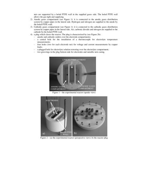
nets are supported by a holed PTFE wall in the supplied gases side. The holed PTFE wallallows the gas tight and supplying.2) Anodic gases compartment (see Figure 1): it is c<strong>on</strong>nected to the anodic gases distributi<strong>on</strong>system by copper pipes in the lateral side. Hydrogen and nitrogen are supplied to the anode bythe holed PTFE wall;3) Cathodic gases compartment (see Figure 1): it is c<strong>on</strong>nected to the cathodic gases distributi<strong>on</strong>system by copper pipes in the lateral side. Air, carb<strong>on</strong>ic dioxide and nitrogen are supplied to thecathode by the holed PTFE wall.4) a plug which closes the reactor. The plug is characterized by (see Figure 2b):- anodic and cathodic outlets over the electrode compartments;- a central hole <strong>for</strong> the installati<strong>on</strong> of a thermocouple <strong>for</strong> electrolyte temperaturemeasurements;- four holes (two <strong>for</strong> each electrode net) <strong>for</strong> voltage and current measurements by copperleads;- a plugged hole <strong>for</strong> electrolyte soluti<strong>on</strong> restoring over the electrolyte compartment;- two groovings in the plug bottom side <strong>for</strong> electrodes and metallic nets casing.LT<strong>MCFC</strong> COMPARTMENTANODIC GASESCOMPARTMENTCATHODIC GASESCOMPARTMENTFigure 1 – the experimental reactor (upside view)ELECTRODESa)HOLED PTFEWALLFigure 2 – (a) the experimental reactor (perspective view); b) the reactor plugb)