Boolean Algebra - Etsu
Boolean Algebra - Etsu
Boolean Algebra - Etsu

Create successful ePaper yourself
Turn your PDF publications into a flip-book with our unique Google optimized e-Paper software.
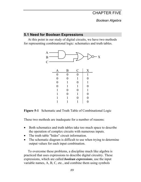
CHAPTER FIVE<strong>Boolean</strong> <strong>Algebra</strong>5.1 Need for <strong>Boolean</strong> ExpressionsAt this point in our study of digital circuits, we have two methodsfor representing combinational logic: schematics and truth tables.ABCXA B C X0 0 0 10 0 1 00 1 0 10 1 1 01 0 0 11 0 1 01 1 0 01 1 1 0Figure 5-1 Schematic and Truth Table of Combinational LogicThese two methods are inadequate for a number of reasons:• Both schematics and truth tables take too much space to describethe operation of complex circuits with numerous inputs.• The truth table "hides" circuit information.• The schematic diagram is difficult to use when trying to determineoutput values for each input combination.To overcome these problems, a discipline much like algebra ispracticed that uses expressions to describe digital circuitry. Theseexpressions, which are called boolean expressions, use the inputvariable names, A, B, C, etc., and combine them using symbols89
90 Computer Organization and Design Fundamentalsrepresenting the AND, OR, and NOT gates. These boolean expressionscan be used to describe or evaluate the output of a circuit.There is an additional benefit. Just like algebra, a set of rules existthat when applied to boolean expressions can dramatically simplifythem. A simpler expression that produces the same output can berealized with fewer logic gates. A lower gate count results in cheapercircuitry, smaller circuit boards, and lower power consumption.If your software uses binary logic, the logic can be represented withboolean expressions. Applying the rules of simplification will make thesoftware run faster or allow it to use less memory.The next section describes the representation of the three primarylogic functions, NOT, AND, and OR, and how to convertcombinational logic to a boolean expression.5.2 Symbols of <strong>Boolean</strong> <strong>Algebra</strong>Analogous behavior can be shown between boolean algebra andmathematical algebra, and as a result, similar symbols and syntax canbe used. For example, the following expressions hold true in math.0 · 0 = 0 0 · 1 = 0 1 · 0 = 0 1 · 1 = 1This looks like the AND function allowing an analogy to be drawnbetween the mathematical multiply and the boolean AND functions.Therefore, in boolean algebra, A AND'ed with B is written A · B.AX = A · BBFigure 5-2 <strong>Boolean</strong> Expression for the AND FunctionMathematical addition has a similar parallel in boolean algebra,although it is not quite as flawless. The following four mathematicalexpressions hold true for addition.0 + 0 = 0 0 + 1 = 1 1 + 0 = 1 1 + 1 = 2The first three operations match the OR function, and if the lastoperation is viewed as having a non-zero result instead of the decimalresult of two, it too can be viewed as operating similar to the OR
Chapter 5: <strong>Boolean</strong> <strong>Algebra</strong> 91function. Therefore, the boolean OR function is analogous to themathematical function of addition.ABX = A + BFigure 5-3 <strong>Boolean</strong> Expression for the OR FunctionAn analogy cannot be made between the boolean NOT and anymathematical operation. Later in this chapter we will see how the NOTfunction, unlike AND and OR, requires its own special theorems foralgebraic manipulation. The NOT is represented with a bar across theinverted element.AX = AFigure 5-4 <strong>Boolean</strong> Expression for the NOT FunctionThe NOT operation may be used to invert the result of a largerexpression. For example, the NAND function which places an inverterat the output of an AND gate is written as:X = A · BSince the bar goes across A · B, the NOT is performed after the AND.Let's begin with some simple examples. Can you determine theoutput of the boolean expression 1 + 0 + 1? Since the plus-signrepresents the OR circuit, the expression represents 1 or 0 or 1.1011Figure 5-5 Circuit Representation of the <strong>Boolean</strong> Expression 1+0+1Since an OR-gate outputs a 1 if any of its inputs equal 1, then1 + 0 + 1 = 1.The two-input XOR operation is represented using the symbol ⊕,but it can also be represented using a boolean expression. Basically, the
92 Computer Organization and Design Fundamentalstwo-input XOR equals one if A = 0 and B = 1 or if A = 1 and B = 0.This gives us the following expression.X = A ⊕ B = A·B + A·BThe next section shows how the boolean operators ·, +, ⊕, and theNOT bar may be combined to represent complex combinational logic.5.3 <strong>Boolean</strong> Expressions of Combinational LogicJust as mathematical algebra combines multiplication and additionto create complex expressions, boolean algebra combines AND, OR,and NOT functions to represent complex combinational logic. Ourexperience with algebra allows us to understand the expressionY = X · (X +5) + 3. The decimal value 5 is added to a copy of X, theresult of which is then multiplied by a second copy of X. Lastly, adecimal 3 is added and the final result is assigned to Y.This example shows us two things. First, each mathematicaloperation has a priority, e.g., multiplication is performed beforeaddition. This priority is referred to as precedence. Second, variablessuch X can appear multiple times in an expression, each appearancerepresenting the current value of X.<strong>Boolean</strong> algebra allows for the same operation. Take for examplethe circuit shown in Figure 5-6.ABCXFigure 5-6 Sample of Multi-Level Combinational LogicIn Chapter 4, we determined the truth table for this circuit by takingthe input signals A, B, and C from left to right through each gate. Asshown in Figure 5-7, we can do the same thing to determine theboolean expression.Notice the use of parenthesis in step c. Just as in mathematicalalgebra, parenthesis can be used to force the order in which operationsare taken. In the absence of parenthesis, however, the AND, OR, andNOT functions have an order of precedence.
Chapter 5: <strong>Boolean</strong> <strong>Algebra</strong> 93ABCABCBBA · BXXa) B goes through thefirst inverter whichoutputs a Bb) A and B go throughthe AND gatewhich outputsA · B.ABCBA · B(A · B) + CXc) A · B and C gothrough the ORgate which outputs(A · B) + C.ABCBA · B(A · B) + CX(A · B) + Cd) The output of theOR gate goesthrough a secondinverter giving usour result.Figure 5-7 Creating <strong>Boolean</strong> Expression from Combinational LogicTo begin with, AND takes precedence over OR unless overridden byparenthesis. NOT is a special case in that it can act like a set ofparenthesis. If the bar indicating the NOT function spans a singlevariable, it takes precedence over AND and OR. If, however, the NOTbar spans an expression, the expression beneath the bar must beevaluated before the NOT is taken. Figure 5-8 presents two examplesof handling precedence with the NOT function.ABX = A · BABX = A · BFigure 5-8 Examples of the Precedence of the NOT Function
94 Computer Organization and Design FundamentalsUnderstanding this is vital because unlike the mathematical inverse, thetwo expressions below are not equivalent.A · B ≠ A · BLet's do an example addressing precedence with a more complexboolean expression. Using parenthesis and the order of precedence, theboolean expression below has a single interpretation.X = A · D + (A + B + C)The following steps show the order to evaluate the above expression.1. OR B with C because the operation is contained under a singleNOT bar and is contained within the lowest set of parenthesis2. Invert the result of step 1 because NOT takes precedence over OR3. OR A with the result of step 2 because of the parenthesis4. Invert result of step 35. AND A and D because AND takes precedence over OR6. OR the results of steps 4 and 5We can use this order of operations to convert the expression to itsschematic representation. By starting with a list of inputs to the circuit,then passing each input through the correct gates, we can develop thecircuit. Figure 5-9 does just this for the previous boolean expression.We list the inputs for the expression, A, B, C, and D, on the left side ofthe figure. These inputs are then passed through the gates using thesame order as the steps shown above. The number inside each gate ofthe figure corresponds to the order of the steps.ABCD1 253 46XFigure 5-9 Example of a Conversion from a <strong>Boolean</strong> Expression
Chapter 5: <strong>Boolean</strong> <strong>Algebra</strong> 95The following sections show how boolean expressions can be usedto modify combinational logic in order to reduce complexity orotherwise modify its structure.5.4 Laws of <strong>Boolean</strong> <strong>Algebra</strong>The manipulation of algebraic expressions is based on fundamentallaws. Some of these laws extend to the manipulation of booleanexpressions. For example, the commutative law of algebra which statesthat the result of an operation is the same regardless of the order ofoperands holds true for boolean algebra too. This is shown for the ORfunction applied to two variables in the truth tables of Figure 5-10.A B A + B A B B + A0 0 0+0 = 0 0 0 0+0 = 00 1 0+1 = 1 0 1 1+0 = 11 0 1+0 = 1 1 0 0+1 = 11 1 1+1 = 1 1 1 1+1 = 1Figure 5-10 Commutative Law for Two Variables OR'ed TogetherNot only does Figure 5-10 show how the commutative law appliesto the OR function, it also shows how truth tables can be used inboolean algebra to prove laws and rules. If a rule states that twoboolean expressions are equal, then by developing the truth table foreach expression and showing that the output is equal for allcombinations of ones and zeros at the input, then the rule is proventrue.Below, the three fundamental laws of boolean algebra are givenalong with examples.Commutative Law: The results of the boolean operations AND andOR are the same regardless of the order of their operands.A + B = B + AA · B = B · AAssociative Law: The results of the boolean operations AND and ORwith three or more operands are the same regardless of which pair ofelements are operated on first.
96 Computer Organization and Design FundamentalsA + (B + C) = (A + B) + CA · (B · C) = (A · B) · CDistributive Law: The AND'ing of an operand with an OR expressionis equivalent to OR'ing the results of an AND between the first operandand each operand within the OR expression.A · (B + C) = A · B + A · CThe next section uses truth tables and laws to prove twelve rules ofboolean algebra.5.5 Rules of <strong>Boolean</strong> <strong>Algebra</strong>5.5.1 NOT RuleIn algebra, the negative of a negative is a positive and taking theinverse of an inverse returns the original value. Although the NOT gatedoes not have an equivalent in mathematical algebra, it operates in asimilar manner. If the boolean inverse of a boolean inverse is taken, theoriginal value results.This is proven with a truth table.A = AA A A0 1 01 0 1Since the first column and the third column have the same pattern ofones and zeros, they must be equivalent. Figure 5-11 shows this rule inschematic form.AA = AFigure 5-11 Schematic Form of NOT Rule5.5.2 OR RulesIf an input to a logic gate is a constant 0 or 1 or if the same signal isconnected to more than one input of a gate, a simplification of the
Chapter 5: <strong>Boolean</strong> <strong>Algebra</strong> 97expression is almost always possible. This is true for the OR gate as isshown with the following four rules for simplifying the OR function.First, what happens when one of the inputs to an OR gate is aconstant logic 0? It turns out that the logic 0 input drops out leavingthe remaining inputs to stand on their own. Notice that the two columnsin the truth table below are equivalent thus proving this rule.Rule: A + 0 = AA A + 00 0+0 = 01 1+0 = 1What about inputting a logic 1 to an OR gate? In this case, a logic 1forces the other operands into the OR gate to drop out. Notice that theoutput column (A + 1) is always equal to 1 regardless of what A equals.Therefore, the output of this gate will always be 1.Rule: A + 1 = 1A A + 10 0+1 = 11 1+1 = 1If the same operand is connected to all of the inputs of an OR gate,we find that the OR gate has no effect. Notice that the two columns inthe truth table below are equivalent thus proving this rule.A A + ARule: A + A = A 0 0+0 = 01 1+1 = 1Another case of simplification occurs when an operand is connectedto one input of a two-input OR gate and its inverse is connected to theother. In this case, either the operand is equal to a one or its inverse is.There is no other possibility. Therefore, at least one logic 1 isconnected to the inputs of the OR gate. This gives us an output of logic1 regardless of the inputs.A A + ARule: A + A = 1 0 0+1 = 11 1+0 = 15.5.3 AND RulesJust as with the OR gate, if either of the inputs to an AND gate is aconstant (logic 0 or logic 1) or if the two inputs are the same or inverses
98 Computer Organization and Design Fundamentalsof each other, a simplification can be performed. Let's begin with thecase where one of the inputs to the AND gate is a logic 0. Rememberthat an AND gate must have all ones at its inputs to output a one. Inthis case, one of the inputs will always be zero forcing this AND toalways output zero. The truth table below shows this.Rule: A · 0 = 0A A · 00 0 · 0 = 01 1 · 0 = 0If one input of a two-input AND gate is connected to a logic 1, thenit only takes the other input going to a one to get all ones on the inputs.If the other input goes to zero, the output becomes zero. This meansthat the output follows the input that is not connected to the logic 1.Rule: A · 1 = AA A · 10 0 · 1 = 01 1 · 1 = 1If the same operand is connected to all of the inputs of an AND gate,we get a simplification similar to that of the OR gate. Notice that thetwo columns in the truth table below are equivalent proving this rule.Rule: A · A = AA A · A0 0 · 0 = 01 1 · 1 = 1Last of all, when an operand is connected to one input of a two-inputAND gate and its inverse is connected to the other, either the operand isequal to a zero or its inverse is equal to zero. There is no otherpossibility. Therefore, at least one logic 0 is connected to the inputs ofthe AND gate giving us an output of logic 0 regardless of the inputs.Rule: A · A = 0A A · A0 0 · 1 = 01 1 · 0 = 05.5.4 XOR RulesNow let's see what happens when we apply these same inputconditions to a two-input XOR gate. Remember that a two-input XOR
Chapter 5: <strong>Boolean</strong> <strong>Algebra</strong> 99gate outputs a 1 if its inputs are different and a zero if its inputs are thesame.If one of the inputs to a two-input XOR gate is connected to a logic0, then the gate's output follows the value at the second input. In otherwords, if the second input is a zero, the inputs are the same forcing theoutput to be zero and if the second input is a one, the inputs aredifferent and the output equals one.Rule: A ⊕ 0 = AA A ⊕ 00 0 ⊕ 0 = 01 1 ⊕ 0 = 1If one input of a two-input XOR gate is connected to a logic 1, thenthe XOR gate acts as an inverter as shown in the table below.Rule: A ⊕ 1 = AA A ⊕ 10 0 ⊕ 1 = 11 1 ⊕ 1 = 0If the same operand is connected to both inputs of a two-input XORgate, then the inputs are always the same and the gate outputs a 0.Rule: A ⊕ A = 0A A ⊕ A0 0 ⊕ 0 = 01 1 ⊕ 1 = 0Lastly, if the inputs of a two-input XOR gate are inverses of eachother, then the inputs are always different and the output is 1.Rule: A ⊕ A = 1A A ⊕ A0 0 ⊕ 1 = 11 1 ⊕ 0 = 15.5.5 Derivation of Other RulesIf we combine the NOT, OR, and AND rules with the commutative,associative, and distributive laws, we can derive other rules for booleanalgebra. This can be shown with the following example.ExampleProve that A + A·B = A
100 Computer Organization and Design FundamentalsSolutionA + A·B = A·1 + A·BRule: A · 1 = A= A·(1 + B) Distributive Law= A·(B + 1) Commutative Law= A·1 Rule: A + 1 = 1= A Rule: A · 1 = ARemember also that rules of boolean algebra can be proven using atruth table. The example below uses a truth table to derive another rule.ExampleProveA + A ⋅ B = A + BSolutionThe truth table below goes step-by-step through both sides of theexpression to prove that A + A ⋅ B = A + B .A B A A·B A + A·B A + B0 0 1 0 0 00 1 1 1 1 11 0 0 0 1 11 1 0 0 1 1The mathematical "F-O-I-L" principle, based on the distributive law,works in boolean algebra too. FOIL is a memory aid referring to themultiplication pattern for multiplying quadratic equations. It stands for:F – AND the first terms from each OR expressionO – AND the outside terms (the first term from the first ORexpression and the last term from the last OR expression)I – AND the inside terms (the last term from the first ORexpression and the first term from the last OR expression)L – AND the last terms from each OR expressionExampleProve (A + B)·(A + C) = A + B·C
Chapter 5: <strong>Boolean</strong> <strong>Algebra</strong> 101Solution(A + B)·(A + C) = (A + B)·A + (A + B)·C Distributive Law= A·A + B·A + A·C + B·C Distributive Law= A + B·A + A·C + B·C Rule: A·A = A= A + A·B + A·C + B·C Commutative Law= A + A·C + B·C Rule: A + A·B = A= A + B·C Rule: A + A·B = ANow that you have a taste for the manipulation of booleanexpressions, the next section will show examples of how complexexpressions can be simplified.5.6 SimplificationMany students of algebra are frustrated by problems requiringsimplification. Sometimes it feels as if extrasensory perception isrequired to see where the best path to simplification lies. Unfortunately,boolean algebra is no exception. There is no substitute for practice.Therefore, this section provides a number of examples of simplificationin the hope that seeing them presented in detail will give you the toolsyou need to simplify the problems on your own.The rules of the previous section are summarized in Figure 5-12.1. A = A9. A ⋅ A = 02. A + 0 = A 10. A ⊕ 0 = A3. A +1 = 111. A ⊕1 = A4. A + A = A 12. A ⊕ A = 05. A + A = 1 13. A ⊕ A = 16. A ⋅ 0 = 014. A + A⋅B = A7. A ⋅1 = A15. A + A ⋅ B = A + B8. A ⋅ A = A 16. ( A + B)⋅ ( A + C)= A + B ⋅ CFigure 5-12 Rules of <strong>Boolean</strong> <strong>Algebra</strong>
102 Computer Organization and Design FundamentalsExampleSimplify (A·B + C)(A·B + D)SolutionFrom the rules of boolean algebra, we know that (A + B)(A + C) =A + BC. Substitute A·B for A, C for B, and D for C and we get:Example(A·B + C)(A·B + D) = A·B + C·DSimplify ( A + B)⋅ ( B + B)Solution(A + B)·1 Anything OR'ed with its inverse is 1(A + B) Anything AND'ed with 1 is itselfExampleSimplify B ⋅ ( A + A ⋅ B)Solution_ _ _B·A + B·A·B Distributive Law_ _ _B·A + A·B·B Associative Law_ _B·A + A·0 Anything AND'ed with its inverse is 0_B·A + 0 Anything AND'ed with 0 is 0_B·AAnything OR'ed with 0 is itself_A·BAssociative LawExampleSimplify ( A + B)⋅ ( A + B)
Solution_ _ _ _A·A + A·B + B·A + B·BChapter 5: <strong>Boolean</strong> <strong>Algebra</strong> 103Use FOIL to distribute terms_ _0 + A·B + B·A + 0 Anything AND'ed with its inverse is 0_ _A·B + B·AAnything OR'ed with 0 is itselfExampleSimplifyA ⋅ B ⋅ C+A ⋅ B ⋅ C +A ⋅ B ⋅C+A ⋅ B ⋅ CSolution_ _ _ _ _A·(B·C + B·C + B·C + B·C) Distributive Law_ _ __A·(B·(C + C) + B·(C + C)) Distributive Law_ _A·(B·1 + B·1) Anything OR'ed with its inverse is 1_ _A·(B + B)Anything AND'ed with 1 is itself_A·1 Anything OR'ed with its inverse is 1_AAnything AND'ed with 1 is itself5.7 DeMorgan's TheoremSome of you may have noticed that the truth tables for the AND andOR gates are similar. Below is a comparison of the two operations.ANDORA B X = A·B A B X = A+B0 0 0 0 0 00 1 0 0 1 11 0 0 1 0 11 1 1 1 1 1Okay, so maybe they're not exactly the same, but notice that theoutput for each gate is the same for three rows and different for the
104 Computer Organization and Design Fundamentalsfourth. For the AND gate, the row that is different occurs when all ofthe inputs are ones, and for the OR gate, the different row occurs whenall of the inputs are zeros. What would happen if we inverted the inputsof the AND truth table?AND of inverted inputsORA B_ _X = A·B A B X = A+B0 0 1 0 0 00 1 0 0 1 11 0 0 1 0 11 1 0 1 1 1The two truth tables are still not quite the same, but they are quiteclose. The two truth tables are now inverses of one another. Let's takethe inverse of the output of the OR gate and see what happens.AND of inverted inputsOR with inverted output_ _____A B X = A·B A B X = (A+B)0 0 1 0 0 10 1 0 0 1 01 0 0 1 0 01 1 0 1 1 0So the output of an AND gate with inverted inputs is equal to theinverted output of an OR gate with non-inverted inputs. A similar proofcan be used to show that the output of an OR gate with inverted inputsis equal to the inverted output of an AND gate with non-invertedinputs. This resolves our earlier discussion where we showed that theNOT gate cannot be distributed to the inputs of an AND or an OR gate.This brings us to DeMorgan's Theorem, the last <strong>Boolean</strong> lawpresented in this chapter.A + B = A · BA + B = A · BThe purpose of DeMorgan's Theorem is to allow us to distribute aninverter from the output of an AND or OR gate to the gate's inputs. Indoing so, an AND gate is switched to an OR gate and an OR gate is
Chapter 5: <strong>Boolean</strong> <strong>Algebra</strong> 105switched to an AND gate. Figure 5-13 shows how pushing the inverterfrom the output of a gate to its inputs.a.) Pushing an inverter through an AND gate flips it to an OR gateb.) Pushing an inverter through an OR gate flips it to an AND gateFigure 5-13 Application of DeMorgan's TheoremDeMorgan's Theorem applies to gates with three or more inputs too.A + B + C + D = (A + B)·(C + D)_ _ _ _= (A·B)·(C·D)_ _ _ _= A·B·C·DOne of the main purposes of DeMorgan's Theorem is to distributeany inverters in a digital circuit back to the inputs. This typicallyimproves the circuit's performance by removing layers of logic and canbe done either with the boolean expression or the schematic. Eitherway, the inverters are pushed from the output side to the input side onegate at a time. The sequence of steps in Figure 5-14 shows this processusing a schematic.It is a little more difficult to apply DeMorgan's Theorem to aboolean expression. To guarantee that the inverters are beingdistributed properly, it is a good idea to apply DeMorgan's Theorem inthe reverse order of precedence for the expression.A · B + CStep 1: The AND takes precedence over the OR, sodistribute inverter across the OR gate first.
106 Computer Organization and Design FundamentalsA · B · CStep 2: Now distribute the inverter across the A·Bterm.(A + B) · C Step 3: In this final case, the use of parenthesis isvital.ABCXa.) Push inverter through the OR gate distributing it to the inputsABCXb.) Push inverter through the AND gate distributing it to the inputsABCc.) Two inverters at B input cancel each otherABCXXFigure 5-14 Schematic Application of DeMorgan's Theorem5.8 What's Next?Using the methods presented in this chapter, a boolean expressioncan be manipulated into whatever form best suits the needs of thecomputer system. As far as the binary operation is concerned, twocircuits are the same if their truth tables are equivalent. The circuits,however, may not be the same when measuring performance or whencounting the number of gates it took to implement the circuit. The
Chapter 5: <strong>Boolean</strong> <strong>Algebra</strong> 107optimum circuit for a specific application can be designed using thetools presented in this chapter.In Chapter 6, we will show how the rules presented in this chapterare used to take any boolean expression and put it into one of twostandard formats. The standard formats allow for quicker operation andsupport the use of programmable hardware components. Chapter 6 alsopresents some methods to convert truth tables into circuitry. It will beour first foray into designing circuitry based on a system specification.Problems1. List three drawbacks of using truth tables or schematics fordescribing a digital circuit.2. List three benefits of a digital circuit that uses fewer gates.3. True or False: <strong>Boolean</strong> expressions can be used to optimize thelogic functions in software.4. Convert the following boolean expressions to their schematicequivalents. Do not modify the original expression___a.) A·B + C_ _ ___b.) A·B·C + A·B + A·C_________ _c.) (A + B·C) + A·D_ _d.) A·B + A·B5. Convert each of the digital circuits shown below to theircorresponding boolean expressions without simplification.a.)ABX
108 Computer Organization and Design Fundamentalsb.)ABCXc.)ABX6. Apply DeMorgan's Theorem to each of the following expressionsso that the NOT bars do not span more than a single variable._______a.) A·C + B_______________b.) D(C + B)(A + B)_ ____c.) A + B + C + (AB)7. Simplify each of the following expressions._a.) B·A + B·A_b.) (A + B)(B + A)_ ____c.) A + B + C + (AB)_d.) B(A + A·B)__e.) (A + B)(A + B)_ ____ _f.) B + (AB) + C