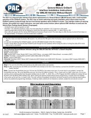
Wiring the OEM-2 and aftermarket stereo to a GM factory Bose ...
Wiring the OEM-2 and aftermarket stereo to a GM factory Bose ...
Wiring the OEM-2 and aftermarket stereo to a GM factory Bose ...

Create successful ePaper yourself
Turn your PDF publications into a flip-book with our unique Google optimized e-Paper software.
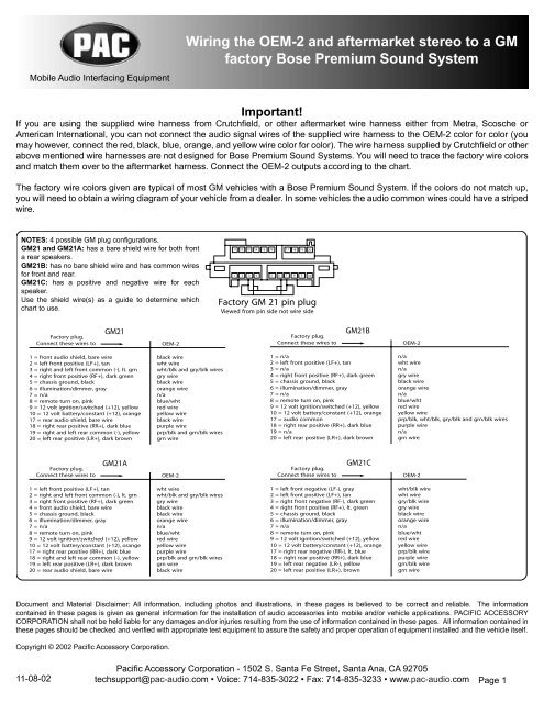
Mobile Audio Interfacing Equipment<strong>Wiring</strong> <strong>the</strong> <strong>OEM</strong>-2 <strong>and</strong> <strong>aftermarket</strong> <strong>stereo</strong> <strong>to</strong> a <strong>GM</strong>fac<strong>to</strong>ry <strong>Bose</strong> Premium Sound SystemImportant!If you are using <strong>the</strong> supplied wire harness from Crutchfi eld, or o<strong>the</strong>r <strong>aftermarket</strong> wire harness ei<strong>the</strong>r from Metra, Scosche orAmerican International, you can not connect <strong>the</strong> audio signal wires of <strong>the</strong> supplied wire harness <strong>to</strong> <strong>the</strong> <strong>OEM</strong>-2 color for color (youmay however, connect <strong>the</strong> red, black, blue, orange, <strong>and</strong> yellow wire color for color). The wire harness supplied by Crutchfi eld or o<strong>the</strong>rabove mentioned wire harnesses are not designed for <strong>Bose</strong> Premium Sound Systems. You will need <strong>to</strong> trace <strong>the</strong> fac<strong>to</strong>ry wire colors<strong>and</strong> match <strong>the</strong>m over <strong>to</strong> <strong>the</strong> <strong>aftermarket</strong> harness. Connect <strong>the</strong> <strong>OEM</strong>-2 outputs according <strong>to</strong> <strong>the</strong> chart.The fac<strong>to</strong>ry wire colors given are typical of most <strong>GM</strong> vehicles with a <strong>Bose</strong> Premium Sound System. If <strong>the</strong> colors do not match up,you will need <strong>to</strong> obtain a wiring diagram of your vehicle from a dealer. In some vehicles <strong>the</strong> audio common wires could have a stripedwire.NOTES: 4 possible <strong>GM</strong> plug confi gurations.<strong>GM</strong>21 <strong>and</strong> <strong>GM</strong>21A: has a bare shield wire for both fronta rear speakers.<strong>GM</strong>21B: has no bare shield wire <strong>and</strong> has common wiresfor front <strong>and</strong> rear.<strong>GM</strong>21C: has a positive <strong>and</strong> negative wire for eachspeaker.Use <strong>the</strong> shield wire(s) as a guide <strong>to</strong> determine whichchart <strong>to</strong> use.12 13 14 15 16 17 18 1911 202 3 4 5 6 7 8 91 10Fac<strong>to</strong>ry <strong>GM</strong> 21 pin plugViewed from pin side not wire sideFac<strong>to</strong>ry plug.Connect <strong>the</strong>se wires <strong>to</strong><strong>GM</strong>21<strong>OEM</strong>-2Fac<strong>to</strong>ry plug.Connect <strong>the</strong>se wires <strong>to</strong><strong>GM</strong>21B<strong>OEM</strong>-21 = front audio shield, bare wire2 = left front positive (LF+), tan3 = right <strong>and</strong> left front common (-), lt. grn4 = right front positive (RF+), dark green5 = chassis ground, black6 = illumination/dimmer, gray7 = n/a8 = remote turn on, pink9 = 12 volt ignition/switched (+12), yellow10 = 12 volt battery/constant (+12), orange17 = rear audio shield, bare wire18 = right rear positive (RR+), dark blue19 = right <strong>and</strong> left rear common (-), yellow20 = left rear positive (LR+), dark brownblack wirewht wirewht/blk <strong>and</strong> gry/blk wiresgry wireblack wireorange wiren/ablue/whtred wireyellow wireblack wirepurple wireprp/blk <strong>and</strong> grn/blk wiresgrn wire1 = n/a2 = left front positive (LF+), tan3 = n/a4 = right front positive (RF+), dark green5 = chassis ground, black6 = illumination/dimmer, gray7 = n/a8 = remote turn on, pink9 = 12 volt ignition/switched (+12), yellow10 = 12 volt battery/constant (+12), orange17 = audio common18 = right rear positive (RR+), dark blue19 = n/a20 = left rear positive (LR+), dark brownn/awht wiren/agry wireblack wireorange wiren/ablue/whtred wireyellow wireprp/blk, wht/blk, gry/blk <strong>and</strong> grn/blk wirespurple wiren/agrn wireFac<strong>to</strong>ry plug.Connect <strong>the</strong>se wires <strong>to</strong><strong>GM</strong>21A<strong>OEM</strong>-2Fac<strong>to</strong>ry plug.Connect <strong>the</strong>se wires <strong>to</strong><strong>GM</strong>21C<strong>OEM</strong>-21 = left front positive (LF+), tan2 = right <strong>and</strong> left front common (-), lt. grn3 = right front positive (RF+), dark green4 = front audio shield, bare wire5 = chassis ground, black6 = illumination/dimmer, gray7 = n/a8 = remote turn on, pink9 = 12 volt ignition/switched (+12), yellow10 = 12 volt battery/constant (+12), orange17 = right rear positive (RR+), dark blue18 = right <strong>and</strong> left rear common (-), yellow19 = left rear positive (LR+), dark brown20 = rear audio shield, bare wirewht wirewht/blk <strong>and</strong> gry/blk wiresgry wireblack wireblack wireorange wiren/ablue/whtred wireyellow wirepurple wireprp/blk <strong>and</strong> grn/blk wiresgrn wireblack wire1 = left front negative (LF-), gray2 = left front positive (LF+), tan3 = right front negative (RF-), dark green4 = right front positive (RF+), lt. green5 = chassis ground, black6 = illumination/dimmer, gray7 = n/a8 = remote turn on, pink9 = 12 volt ignition/switched (+12), yellow10 = 12 volt battery/constant (+12), orange17 = right rear negative (RR-), lt. blue18 = right rear positive (RR+), dark blue19 = left rear negative (LR-), yellow20 = left rear positive (LR+), brownwht/blk wirewht wiregry/blk wiregry wireblack wireorange wiren/ablue/whtred wireyellow wireprp/blk wirepurple wiregrn/blk wiregrn wireDocument <strong>and</strong> Material Disclaimer: All information, including pho<strong>to</strong>s <strong>and</strong> illustrations, in <strong>the</strong>se pages is believed <strong>to</strong> be correct <strong>and</strong> reliable. The informationcontained in <strong>the</strong>se pages is given as general information for <strong>the</strong> installation of audio accessories in<strong>to</strong> mobile <strong>and</strong>/or vehicle applications. PACIFIC ACCESSORYCORPORATION shall not be held liable for any damages <strong>and</strong>/or injuries resulting from <strong>the</strong> use of information contained in <strong>the</strong>se pages. All information contained in<strong>the</strong>se pages should be checked <strong>and</strong> verifi ed with appropriate test equipment <strong>to</strong> assure <strong>the</strong> safety <strong>and</strong> proper operation of equipment installed <strong>and</strong> <strong>the</strong> vehicle itself.Copyright © 2002 Pacifi c Accessory Corporation.11-08-02Pacifi c Accessory Corporation - 1502 S. Santa Fe Street, Santa Ana, CA 92705techsupport@pac-audio.com • Voice: 714-835-3022 • Fax: 714-835-3233 • www.pac-audio.com Page 1
NOTES: 2 possible plug confi gurations.<strong>GM</strong>32: has one audio shield wire.<strong>GM</strong>32A: has two audio shield wires.Use <strong>the</strong> shield wire(s) as a reference <strong>to</strong>select which chart <strong>to</strong> use.E1 2 3 4 5 6 7 8 9 10 11 12 13 14 15 16F1 2 3 4 5 6 7 8 9 10 11 12 13 14 15 16Fac<strong>to</strong>ry <strong>GM</strong> 32 pin plugViewed from pin side not wire sideFac<strong>to</strong>ry plug.Connect <strong>the</strong>se wires <strong>to</strong><strong>GM</strong>32<strong>OEM</strong>-2Fac<strong>to</strong>ry plug.Connect <strong>the</strong>se wires <strong>to</strong><strong>GM</strong>32A<strong>OEM</strong>-2Row E1 = n/a2 = n/a3 = remote turn on4 = n/a5 = n/a6 = n/a7 = n/a8 = n/a9 = n/a10 = n/a12 = left rear positive (LR+)13 = n/a14 = n/a15 = right rear positive (RR+)16 = chassis groundn/an/ablue/wht wiren/an/an/an/an/an/an/agrn wiren/an/aprp wireblack wireRow E1 = n/a2 = n/a3 = remote turn on4 = n/a5 = n/a6 = n/a7 = n/a8 = n/a9 = n/a10 = n/a12 = left rear positive (LR+)13 = rear audio shield, bare wire14 = rear audio common return (-)15 = right rear positive (RR+)16 = chassis groundn/an/ablue/wht wiren/an/an/an/an/an/an/agrn wireblack wireprp/blk <strong>and</strong> grn/blk wireprp wireblack wireRow F1 = constant 12 volts2 = accessory 12 volts3 = antenna remote turn on4 = illumination/dimmer5 = n/a6 = n/a7 = n/a8 = n/a9 = n/a10 = n/a12 = left front positive (LF+)13 = audio shield, bare wire14 = audio common return (-)15 = right front positive (RF+)16 = n/ayellow wirered wireblue wireorangen/an/an/an/an/an/awht wireblack wireprp/blk,grn/blk,gry/blk <strong>and</strong> wht/blk wiresgry wiren/aRow F1 = constant 12 volts2 = accessory 12 volts3 = antenna remote turn on4 = illumination/dimmer5 = n/a6 = n/a7 = n/a8 = n/a9 = n/a10 = n/a12 = left front positive (LF+)13 = front audio shield, bare wire14 = front audio common return (-)15 = right front positive (RF+)16 = n/ayellow wirered wireblue wireorangen/an/an/an/an/an/awht wireblack wiregry/blk <strong>and</strong> wht/blk wiresgry wiren/a<strong>GM</strong>ABHJBLACKWHITEBLUEFECDKLViewed from pin side not wire sideFac<strong>to</strong>ry plug.Connect <strong>the</strong>se wires <strong>to</strong><strong>GM</strong>12A = right front positive (RF+), lt. grnB = left front positive (LF+), tanC = front shield, bare wireD = right front negative, left front negativeE = remote turn on, pinkF = 12 volt ignition/switched (+12), yellowG = ground, blackH = left rear positive (LR+), brownJ = right rear positive (RR+), dark blueK = left rear negative, right rear negativeL = rear shield, bare wireM = illumination/dimmer, grayon separate two pin, white plug, orangewire is constant 12 volts.Late 1984 <strong>and</strong> later models only<strong>OEM</strong>-2gry wirewht wireblack wiregry/blk <strong>and</strong> wht/blk wireblue/wht wirered wireblack wiregreen wireprp wireprp/blk <strong>and</strong> grn/blk wireblack wireorange wireyellow wirePacifi c Accessory Corporation - 1502 S. Santa Fe Street, Santa Ana, CA 92705techsupport@pac-audio.com • Voice: 714-835-3022 • Fax: 714-835-3233 • www.pac-audio.com Page 2