Experiences of Wet Type Electrostatic Precipitator ... - isesp
Experiences of Wet Type Electrostatic Precipitator ... - isesp
Experiences of Wet Type Electrostatic Precipitator ... - isesp

Create successful ePaper yourself
Turn your PDF publications into a flip-book with our unique Google optimized e-Paper software.
<strong>Experiences</strong> <strong>of</strong> <strong>Wet</strong> <strong>Type</strong> <strong>Electrostatic</strong> <strong>Precipitator</strong> Successfully Appliedfor SO 3 Mist Removal in Boilers Using High Sulfur Content FuelHidekatsu Fujishima and Chikayuki NagataMitsubishi Heavy Industries, Ltd.Kobe Shipyard & Machinery Works1-1, Wadasaki-cho 1-Chome, Hyogo-ku,KOBE 652-8585 JAPANABSTRACTIn thermal power plants, especially using high sulfur content fuel, much attention is recently paid to SO 3emission, because gaseous SO 3 in flue gas is condensed to sulfuric acid mist (SO 3 mist) in the wet typeFGD, which is installed to meet SO 2 emission regulation. SO 3 mist is very fine under-sub-micron sizedparticulate matter (PM), which is very visible even if the concentration is relatively low, and causes airpollution. SO 3 is <strong>of</strong>ten recognized as a part <strong>of</strong> the total SO x . However, recently, discussion comes out,especially in the United States, that the condensed SO 3 mist should be included in the total dust instead<strong>of</strong> SO x and regulated together with solid dust. In order to remove SO 3 mist from flue gas, wet typeelectrostatic precipitator (WESP) installed in the horizontal gas flow at downstream <strong>of</strong> FGD (Flue GasDesulfurization System) is one <strong>of</strong> the best solutions and the most proven technology at this moment.This paper describes the experiences <strong>of</strong> WESP successfully applied in Japan and Europe, and alsoshows the advantages <strong>of</strong> the technology. Measuring method <strong>of</strong> solid dust and SO 3 concentration is avery important issue for WESP application, which is discussed in this paper as well.1. INTRODUCTIONWhen high sulfur contained fuel is burned in boiler furnace, sulfur content in fuel is combined withoxygen and mainly forms gaseous SO 2 , but some <strong>of</strong> the content is furthermore oxidized to gaseousSO 3 . When SCR is equipped in the plant, the conversion rate from SO 2 to SO 3 increases becauseadditional SO 3 is converted from SO 2 by catalytic effect <strong>of</strong> SCR. The conversion rate depends onvarious plant conditions, but it may typically be around 2 - 3 % in coal fired boiler plant, and around 5 -6% in oil fired boiler. In oil fired boiler, and boiler using fuels with similar characteristics such aspetro-cokes, asphalt, orimulsion, etc., heavy metal components contained in ash adhered on thesurface <strong>of</strong> boiler tubes will have catalytic effect to enhance the conversion rate.In the flue gas temperature at outlet <strong>of</strong> air pre-heater, most <strong>of</strong> SO 3 is still in gaseous condition. However,using high sulfur fuel means that SO 2 concentration is high, and if wet type FGD is equipped in order tomeet the requirement to reduce SO 2 emission, the flue gas temperature will be reduced to watersaturated condition, and in this gas quenching process, gaseous SO 3 will be combined with water (H 2 O)and liquidized to be sulfuric acid mist (H 2 SO 4 ), which is also <strong>of</strong>ten called as SO 3 mist. This SO 3 mist isvery fine particle whose diameter is under-sub-micron size.In FGD, gaseous SO 2 is chemically absorbed but SO 3 mist is hardly captured chemically because it isin particulate (liquid) phase. Larger particles can be physically captured in FGD, however SO 3 mist istoo fine to be physically captured in FGD, so that such SO 3 mist particles will slip over to FGD outlet.Once SO 3 mist is discharged from stack, under-sub-micron sized particles are very visible, and it is<strong>of</strong>ten called as bluish plume. SO 3 is just a small portion <strong>of</strong> total SOx generated from the boiler, but it isso clear to be seen since the number <strong>of</strong> the particles is very large in accordance with their smalldiameter, and it causes serious “visual pollution” problem. SO 3 mist emission is recognized as problemalso in the viewpoint <strong>of</strong> opacity and PM 2.5 . Recently, there is discussion that condensibles including SO 3mist should also be added to total dust, and if condensibles are to be considered as a part <strong>of</strong> dust, theymust be removed to meet the dust emission regulation.ICESP IX
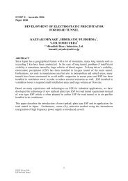
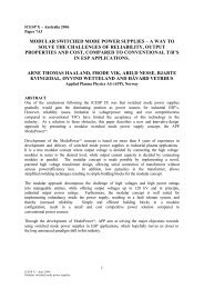
2In order to eliminate such SO 3 mist, WESP installed at downstream <strong>of</strong> FGD is one <strong>of</strong> the best solutions.It collects fine particles including SO 3 mist electrostatically with a very high collecting efficiency. At thesame time, other fine particles, such as boiler dust still remaining at FGD outlet and other FGD carryingover particles, are <strong>of</strong> course also effectively collected in WESP, and the stack plume condition will bemuch improved. (1)(2) Gas flow system with WESP is shown in Fig. 1.Boiler SCRAir Pre-HeaterSO 2(gas)SO 3(gas)NH 3Total conversion rate from SO 2 toSO 3 is typically 2 – 3% in coal firedboiler, 5 – 6% in oil fired boiler.BH orDESPCaLimestone,for exampleFGDRemovedSO(gas)2Gas to MistSO (mist)3WESPRemoved EfficientlyTotal DustSO 3(mist)Minimized StackPlumeFGD Carry OverSCR Slip OverNH 3(gas)Removed(NH4) 2 SO 4(solid)Removed(NH4) 2 SO 4(solid, mist)CaSO 4FGD Carry Over(NH 4 ) 2 SO 4SolidDustRemovedSolidDustRemovedSolidDustSolidDustFig. 1 Gas Flow System and Removal <strong>of</strong> “Total Dust” including SO 3 with WESPFig. 2 Basic Structure <strong>of</strong> Horizontal WESPICESP IX
32. Basic Construction <strong>of</strong> Horizontal WESPThe basic construction <strong>of</strong> horizontal WESP is very similar to conventional Dry ESP design as shown inFig. 2. Flue gas from FGD is introduced horizontally into its casing through inlet nozzle, in which gasdistribution plates are installed and the gas velocity is reduced to be uniformly distributed into the mainpart <strong>of</strong> the casing, where collecting electrodes are set in parallel along the gas flow direction, andbetween collecting electrodes, rigid frame type discharge electrodes, which has special geometry withlong spikes in order to keep high and stable corona discharge, are equipped.3. Process Flow <strong>of</strong> Horizontal WESP3.1 Gas FlowFlue gas from FGD is introduced horizontally into the first section <strong>of</strong> the collecting zone, where most <strong>of</strong>the particulate matters contained in the flue gas are collected on the collecting electrode and separatedfrom the gas. Then it flows to the second section, which is independently energized from the firstsection, and remaining particulate matters are separated also effectively from the gas. If theperformance requirement is extremely high, it is possible to install additional sections within the sameWESP casing. The purified gas is discharged to downstream through outlet nozzle, where misteliminator is installed. In the collecting zone, atomized water is continuously supplied and it containscaustic soda (or magnesium hydroxide as an alternative) and its reactants, so that the outlet gas fromWESP may have carried over water droplets containing some Na- (or Mg-) reactants, and in order toavoid any influence <strong>of</strong> such carried over reactants to WESP outlet dust burden, mist eliminator isrequired. The mist eliminator is washed intermittently by fresh water.3.2 Particulate MattersParticulate matters, such as fine dust and condensibles including SO 3 mist, slipped over from FGD, arenegatively charged when corona discharge occurs between discharge electrode and collectingelectrode, and the electrically charged particles are collected on the surface <strong>of</strong> the collecting electrodesby electrostatic force (Coulomb force). The collected particulate matters on the collecting electrodes arewashed down by atomized water continuously supplied from spray nozzles equipped above electrodes.The washed particulate matters are discharged from hoppers as slurry, and flow into re-circulation tank.3.3 Water FlowIn re-circulation tank, pH <strong>of</strong> discharged slurry is monitored and it controls the dosing amount <strong>of</strong> causticsoda (or magnesium hydroxide as an alternative), in order to keep the pH value <strong>of</strong> water in the tankalways beyond the minimum set value (typically pH = 4). Such pH-controlled water is used as atomizingwater sprayed in WESP. In order to keep SS (suspended solid) value <strong>of</strong> atomizing water under certainvalue (typically < 1,000 ppm), some <strong>of</strong> the re-circulation flow is extracted from auto strainer to FGD, sothat the collected solid dust in WESP is treated finally together with FGD wasting water. Re-circulatingwater is pumped up to the top <strong>of</strong> WESP and atomized into the collecting zone <strong>of</strong> WESP. In this stage,the water is in alkaline side. Atomized water droplets are collected easily on electrodes by electrostaticforce because <strong>of</strong> their larger diameter compared with particulate matters contained in the flue gas, andthey form water film flow on the collecting electrodes. Particulate matters collected by electrostatic forceare captured in this water film flow, and washed down. Collected SO 3 mist reduces pH value <strong>of</strong> waterfilm flow, and it takes the minimum value at the bottom, but it must be still kept beyond the minimum setvalue in order to avoid sulfuric acid corrosion. For the purpose, pH value <strong>of</strong> drainage is monitored andcontrols chemical dosing amount. From the viewpoint <strong>of</strong> sulfuric acid corrosion, the most critical regionis near the boundary part <strong>of</strong> wet and dry conditions, and completely wet region is less severe incorrosion, because oxygen required for oxidation <strong>of</strong> material is at the material surface. Continuousatomizing realizes completely wet condition always upon the collecting electrode surface and othermetal surface exposed to the gas, and it allows comparatively cost-effective materials such as stainlesssteel (316L) to be used, instead <strong>of</strong> higher grade alloy materials.ICESP IX
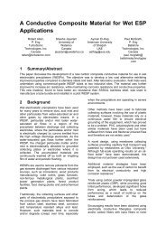
4Fig. 3 Simplified Process Flow Diagram <strong>of</strong> Horizontal WESP4. Advantages <strong>of</strong> Horizontal WESP4.1 Continuous Atomizing System with Chemical AdditiveOur standard WESP to be applied to collect SO 3 mist is equipped with continuous atomizing systemusing re-circulating atomizing water, whose pH is controlled by chemical additive such as caustic sodaor magnesium hydroxide. This continuous atomizing system is equipped not only to clean up electrodesbut also to protect electrodes from sulfuric acid corrosion, and this is one <strong>of</strong> the most important keytechnology. Resin lining can be applied on inner surface <strong>of</strong> the casing for corrosion protection, howeverinner parts such as electrodes requires electrical conductivity and it is very difficult to be applied withFig. 4 Corrosion Speed (Material Thickness Reduction)ICESP IX
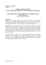
5corrosion protector such as resin lining. Continuous atomizing system is judged to be the best way toprotect inner parts from sulfuric acid corrosion, through the experience which is met in tryingdevelopment <strong>of</strong> periodical washing system, such as follows;In order to select material <strong>of</strong> internal parts including electrodes, at first, the corrosion speed <strong>of</strong> variousmaterials was evaluated in simulated WESP condition by laboratory test, executed in our TakasagoR&D Center. It is very important to take surface potential (voltage) load in count to evaluate WESPcorrosion, since electrodes <strong>of</strong> WESP exist in the condition suffered by corona discharge and suchsurface potential load contributes to accelerate sulfuric acid corrosion. (Any corrosion test ignoring thissurface potential load cannot simulate actual corrosion condition in WESP, and very risky to use forevaluation <strong>of</strong> WESP corrosion.) In the laboratory test, surface potential load <strong>of</strong> 1.5 V was applied oneach test piece, and the test pieces were set in sulfuric acid solution <strong>of</strong> pH 1, which we thought asenough low pH value at that moment. Summary <strong>of</strong> the laboratory test is shown in Fig. 4, and it suggeststhe followings;(1) Corrosion speed experienced in energized WESP (with surface potential load <strong>of</strong> 1.5 V) iscompletely different from ordinary situations (without considering surface potential load). It is veryessential to evaluate WESP corrosion taking surface potential load in count.(2) Under the circumstance in WESP (with surface potential load), high grade materials such asHastelloy or Inconnel are not so good from the view point <strong>of</strong> corrosion protection, and StainlessSteel 316L is rather protective to sulfuric acid corrosion.(3) Even Stainless Steel 316L, which is the best among the test data excepting titanium, sulfuric acidcorrosion proceeds significantly and plate thickness <strong>of</strong> 6 mm, for example, can remain less thanhalf a year.(4) In this test condition, only Ti (titanium) shows significant result. From test piece <strong>of</strong> titanium, nothickness reduction can be detected.In next step, internal parts including electrodes made <strong>of</strong> titanium were applied to WESP <strong>of</strong> commercialsize, and it was installed in actual industrial boiler plant, and was operated with periodic washingsystem (without chemical additive). In the plant in which this WESP was installed, SO 3 concentration atWESP inlet was usually around 40 ppm. Titanium material was expected to be used in this situation,however the result completely betrayed the expectation. Only after three months from starting operation,collecting electrode plates made <strong>of</strong> titanium were broken by sulfuric acid corrosion, and the WESP wasnot possible to be operated at that time. The situation is shown in Fig. 5.The reason <strong>of</strong> the resultcompletely different from the firstexpectation comes from the factthat the previous assumption <strong>of</strong>sulfuric acid solution <strong>of</strong> pH 1adopted in the laboratory test didnot simulate the actual condition.The concentration <strong>of</strong> sulfuric acidsolution on the collectingelectrodes <strong>of</strong> the WESP in Fig. 5was investigated, and it was foundthat actual sulfuric acid conditionwas more severe. SO 3 mist wasdirectly collected on collectingelectrode and the concentration <strong>of</strong>sulfuric acid solution on thecollecting electrode became lessthan 5% (pH = 0) in one hour afterthe washing, and soon it wouldfurthermore be concentrated to 20 –40%, which is in the level thatBrokenCollectingElectrodeFig 5. Situation <strong>of</strong> WESP with Internal Parts made <strong>of</strong> Tiand with Periodic Washing System without ChemicalAdditive, 3 Months after Starting Operationcannot be expressed in “pH” value, and very high percentage compared with assumed “pH 1” in thelaboratory test, which corresponds to 0.5% sulfuric acid solution.ICESP IX
6So, even titanium cannot protect the electrodes from sulfuric acid corrosion in WESP with energizationand with only periodic washing system, and any other materials such as Hastelloy or Inconnel, whichare less protective from corrosion in the circumstance with surface potential load, cannot endure. Andthe continuous atomizing system is concluded to be essential. In large capacity plant <strong>of</strong> utility power,atomized water amount is huge, so that water consumption will be too much if one-through systemwithout re-circulation line is adopted. In order to keep water consumption in reasonable range, adoptingre-circulation line is necessary, and chemical additive, such as caustic soda or magnesium hydroxide,is also required to neutralize sulfuric acid as long as re-circulation line is adopted.4.2 Advantage <strong>of</strong> Horizontal Flow WESPIn order to realize the continuous atomizing system,horizontal gas flow type WESP is almost essential. Ifthe continuous atomizing system is adopted in vertical(especially upward) flow type, droplets from completelywet collecting surface will be re-entrained into gas andsmall droplets will be suspended in the collecting zone.They cause excessive sparks, which decrease theWESP performance, as shown in Fig.6. In the case <strong>of</strong>horizontal WESP, water film flows down gravitationallyand separated from the horizontal gas flow at the bottompart <strong>of</strong> WESP, so that it allows the continuous atomizingsystem.Fig. 6 Vertical WESP Model Test4.3 Consideration <strong>of</strong> Space ChargeEffectHorizontal WESP is very easy to realizemulti-section WESP, such as two-sectiontype, while vertical <strong>Wet</strong> ESP must considerwater droplets influence coming down fromthe upper section. Sulfuric acid mist is so finethat corona current is reduced in the firstsection due to space charge effect, so thatmulti-section is essential. In order to sizeWESP properly, the relationship betweenWESP performance and space charge shallbe grasped, and much experience isrequired for the purpose. Example data <strong>of</strong>performance reduction curve due to spacecharge effect is shown in Fig. 7 and Fig. 8.Space charge amount is proportional to sum<strong>of</strong> total surface area <strong>of</strong> all particlesintroduced into WESP per unit time,therefore when particle concentration rise up,particle size becomes finer, and gas velocityis faster, space charge amount becomeslarger. When space charge becomes large,corona current is significantly reduced(corona quenching effect) and spark overvoltage is reduced (excessive spark over),and as a result, WESP performance will beFig. 7 Performance Reduction Due to SpaceCharge Effect by High SO 3 Concentration atTypical Gas Velocity ConditionFig. 8 Performance Reduction Due to SpaceCharge Effect by High Gas Velocity at Typical SO 3Concentration ConditionICESP IX
7reduced. In the case <strong>of</strong> this type <strong>of</strong> WESP installation, small diameter <strong>of</strong> SO 3 mist and its concentrationare the given conditions, and gas velocity in WESP shall be determined very carefully in order not toreduce the performance too much. Size <strong>of</strong> SO 3 mist has been <strong>of</strong>ten said as “sub-micron”, howeveraccording to our latest measurement in actual plant, diameter <strong>of</strong> SO 3 mist (d 50 ) is found to be less than0.08 micron meters even in mass basedistribution, and less than 0.04 micronmeters in count base distribution. Inrelation with space charge amount, countbase distribution should be taken account,and SO 3 mist <strong>of</strong> “under-sub-micron” size,which is 0.03 - 0.04 micron meters, instead<strong>of</strong> “sub-micron” size, shall be treated inWESP. Such very fine particle sizedistribution cannot be measured by usualimpacting method, and Fig. 9 shows theexample <strong>of</strong> particle size distributionmeasured in an actual plant (SO 3concentration is 20 ppm) by DMA(Differential Mobility Analyzer), which is theparticle analyzing method using equipmentclassifying particles electrostatically, and ispossible to analyze even “under-sub-micron” size particles.Fig. 9 Particle Size Distribution <strong>of</strong> SO 3Mist Measured by DMA in Actual Plant5. Commercial Application References <strong>of</strong> Horizontal WESP5.1 Application in JapanThe first application <strong>of</strong> horizontal type <strong>of</strong> WESP installed at downstream <strong>of</strong> FGD was in 1975, and sincethen in total 25 plants have been equipped with this type <strong>of</strong> WESP in Japan. (2) Among them, we haveexperienced many cases <strong>of</strong> very high sulfuric acid concentration, up to 80ppm. In the very first severalprojects, the technologies have been established, including those to overcome sulfuric acid corrosionand space charge effect by high sulfuric acid concentration, etc., so that no major trouble has beenexperienced in this type <strong>of</strong> WESP since around 1980. Fig. 10 shows the typical case <strong>of</strong> stack plumeelimination, whose SO 3 concentration is approximately 60 ppm at WESP inlet, and less than 1 ppmachieved at WESP outlet. In this plant, WESP outlet gas is not reheated so that water vapor remainsbut sulfuric acid mist has been almost completely eliminated.(a) WESP is “OFF”(b) WESP is “ON” (only water vapor is seen.)Fig. 10 Example <strong>of</strong> Stack Plume Condition(<strong>Wet</strong> Stack, SO 3 concentration at FGD outlet is approx. 60 ppm.)Among the 25 plants mentioned above, application to Japanese utility power company’s commerciallyICESP IX
operated boiler plants are as follows :Tokyo Electric Power Co. (Japan) / Yokosuka Power Station Unit 1(265MW, Coal Oil Mixture Fired, operated since 1985)Chubu Electric Power Co. (Japan) / Hekinan Power Station Unit 1, 2, and 3 (1)8(700MW x 3, Coal Fired, operated respectively since 1991, 1992, and 1993)5.2 Application in EuropeIn 1997, a horizontal WESP was installed in Werndorf Power Station Unit 2, which is 165MW oil firedboiler, is located near Graz, Austria, and was owned by Austrian utility power company STEWEAG atthe time we delivered the WESP. (3) (The owner company <strong>of</strong> the power station has been turned toVerbund nowadays.) This is the first WESP in Europe equipped at downstream <strong>of</strong> FGD in boiler plant.The purpose <strong>of</strong> installing this WESP is to eliminate SO 3 mist plume from stack, and it has been and isbeing operated successfully up to now.6. WESP in FutureAs described above, due to the conditions such as high corrosion possibility, high space charge, etc.,we are judging that horizontal WESP with continuous atomizing <strong>of</strong> re-circulation water whose pH iscontrolled by chemical additive is the most reliable and proven technology to reduce SO 3 from boilerflue gas using high sulfur content fuel. Especially, for large capacity boilers <strong>of</strong> utility power, there maynot exist alternatives with the same grade <strong>of</strong> reliability. However, this type <strong>of</strong> WESP is fairly largeequipment, and we have also recognized thatmore compact equipment will be highlypreferable, especially considering therequirement for retr<strong>of</strong>it installation to existingboiler facilities.As we have already presented (4)(5) , we havedeveloped MDDS (Mitsubishi Di-electricDroplet Scrubber), which is a new type WESPadopting completely new concept to captureSO 3 mist electrostatically on large droplets <strong>of</strong>water. Fig. 11 shows a schematic illustration <strong>of</strong>MDDS. Flue gas is introduced into pre-charger(PC) and SO 3 mist is negatively charged, andthen the gas is introduced into collectingsection (CS). The figure shows 2 collectingsections type MDDS and water is sprayedbelow each CS. This comparatively largeFig. 11 Example <strong>of</strong> Structure <strong>of</strong> MDDSsprayed water droplets are introduced togetherwith pre-charged fine particles <strong>of</strong> dust and SO 3mist to CS to which external electric field is supplied. Sinceparallel plate electrodes are used in CS to form equal electricfield, comparatively large water droplets generate polarizedcharge on their surface, and pre-charged fine particles <strong>of</strong> dustand SO 3 mist are captured on the surface <strong>of</strong> the water dropletswith polarized charge, as shown in Fig. 12. Some <strong>of</strong> such waterdroplets capturing fine particles are collected on electrodes inCS, and some remaining will pass through CS but they arecomparatively large particles and it is possible to be easilycaptured in Mist Eliminator installed at the outlet <strong>of</strong> MDDS. Thespace between PC and 1st CS can be used as absorber, andthe function <strong>of</strong> FGD (SO 2 absorber) can be integrated withMDDS.Fig. 12 Pre-charged ParticlesCaptured on Water Droplets withPolarized ChargeICESP IX
9At present, four industrial boiler plants in Japan are equipped with MDDS, as shown in Table 1.Example photograph <strong>of</strong> the commercially operated MDDS is shown in Fig. 13.MDDS has realized vertical flow WESP and has great advantage in its very small footprint area.However, in this moment, power consumption is comparatively high compared with conventionalhorizontal WESP for the same planning conditions, and it will be a disadvantage <strong>of</strong> MDDS especially if itis applied in a large plant. Additionally, due to some structural design limitation, the maximumapplicable gas flow rate for MDDS is limited as around 300,000m 3 N/h(wet). However, we would like to improve MDDS in order tobe applicable also in large plants such as boiler plants <strong>of</strong> utilitypower in near future.Table 1 Commercially Operated MDDS in JapanGas Flow RateSO 3 (ppm) Dust (mg/m 3 N)(m 3 N/h) inlet outlet inlet outletRemarksA 120,000 1.4 0.1 91.1 1.9 CS: 1 stageB 160,000 31.9 0.9 51.4 5.3 CS: 2 stagesC 170,000 49.8 0.9 35.0 2.0 CS: 2 stagesD 320,000 25.6 4.4 199.0 33.8 CS: 1 stagePlant A and D : with FGD functionPlant B and C : without FGD functionFig. 13 Outside View <strong>of</strong>Commercially Operated MDDS7. Measuring Method <strong>of</strong> SO 37.1 General SituationRecently, in the United States, requirement for WESP to remove condensibles (condensable particles)including SO 3 mist is increasing. In accordance with the concept <strong>of</strong> MACT (Most Achievable ControlTechnology) or BACT (Best Available control Technology), WESP is being recognized as an effectivemeans to reduce condensibles, which should be recognized to be included in “total dust”, and to meetwith the requirement for “total dust” reduction in air permission. (The same consideration, that SO 3 mistshall be included in total dust and regulated as a part <strong>of</strong> dust, is being adopted also in Italy.)In the United States, the most probably specified measuring method for total dust in this moment maybe US EPA Method 5B (7) + Method 202 (8) as shown in Fig. 14, while Japanese most commonmeasuring method is JIS Z 8808 (9) + Spiral Tube Method as shown in Fig. 15.1. Sampling tube with nozzle2. Sampling port in flue gas duct3. Thermometer4. Tubular type filter holder5. Tubular type filter6. Heater8. Drainage bottle9. Pump10. Gas meter11. Heat resistant flexible tube12. Flexible tube13. Spiral tube with mist catcherFig. 14 Typical US Sampling Train for“total dust”(US EPA Method 5B + Method 202)7. Tube for cooling14. Bin for cooling waterFig. 15 Typical Japanese SamplingTrain for “total dust”(JIS Z 8808 + Spiral Tube Method)ICESP IX
10Both sampling trains consist <strong>of</strong> solid dust sampling part with sampling filter, which is commonly used inhigh temperature dust sampling, for example, at inlet and outlet <strong>of</strong> dry ESP, and following SO 3(condensibles) sampling part, which is quite different in US method and Japanese method. In thefollowing clauses, some points to be paid attention in solid dust and SO 3 measurement in wet gascondition. Especially, it is very important to select SO 3 measurement method carefully in order to getaccurate measurement value.7.2 Solid Dust Sampling7.2.1 Filter MaterialFormer part <strong>of</strong> the both sampling trainsis usual measuring method commonlyused in dry dust sampling, howeverwhen it is adopted in wet gas zone, wemust be very careful in absorbing SO 2and SO 3 . US EPA Method 5B basicallyfollows Method 5 (6) , and Method 5specifies the material <strong>of</strong> the samplingfilter as glass fiber. However glassfiber filter is known to absorb SO 2 gasand the absorbing amount is affectedalso by binder material. Fig. 16 showsthe typical example <strong>of</strong> influence <strong>of</strong> SO 2 or SO 3 gas on sampling filter. Even if the sampling filter isheated, glass fiber filter absorbs SO 2 or SO 3 gas and non heat-treated sample (shown as “H 2 SO 4uncorrected” in Fig. 16) includes additional value not contributed by solid dust. This influence differsalso by binder material, even if the same glass fiber material is used for the filter base media. Thisinfluence <strong>of</strong> SO 2 /SO 3 gas can be eliminated if the sampling filter is heat-treated according to JIS Z 8808instruction (250 deg. C x 2 hours) as also shown as “H 2 SO 4 corrected” in Fig. 16. However, in order toavoid such influence <strong>of</strong> SO 2 or SO 3 gas, Silica or Quartz material, which is less affective to SO 2 gas, ishighly recommendable to be selected for the sampling filter.Fig. 16 Influence <strong>of</strong> SO 2 /SO 3 Gas on Sampling Filter7.2.2 Heat-treatment TemperatureShown in Fig. 16, if the sampling filter is heat treated after the sampling in accordance with JIS Z 8808instruction, namely 250 deg. C x 2 hours, influence <strong>of</strong> SO 2 or SO 3 gas may be canceled, however theheat treatment procedure in JIS is different from that specified in US EPA Method 5, which specifies 160deg. C x 6 hours. We consider that heat-treatment temperature specified in EPA method is not highenough to eliminate SO 3 condensation on filter and to obtain accurate value only <strong>of</strong> solid dust, due tothe result <strong>of</strong> a laboratory test, in which we prepared sampling filters spiked with sulfuric acid and theyare heated with both EPA way (160 deg. C x 6 hours) and JIS way (250 deg. C x 2 hours). We testedspiked amount <strong>of</strong> sulfuric acid as two conditions such as equivalent to the conditions sampling 30 ppmand 3 ppm <strong>of</strong> SO 3 in gas. After we treated the filter in 160 deg. C x 6 hours, 7.7% <strong>of</strong> spiked sulfuric acidequivalent to 30 ppm <strong>of</strong> SO 3 still remained on the filter and also 3.8% <strong>of</strong> spiked sulfuric acid equivalentto 3 ppm <strong>of</strong> SO 3 still remained, while after we treated the filter in 250 deg. C x 2 hours, we could notdetect any sulfuric acid remained on the both sampling filters. So, we consider that after-treatment inhigh temperature such as 250 deg. C is highly recommendable, if accurate value <strong>of</strong> solid dustconcentration should be measured.7.3 Condensibles (SO 3 ) SamplingCondensibles (SO 3 ) sampling part is completely different between EPA method and Japanese method.EPA Method 202 specifies to use impingers filled with de-ionized water to absorb condensiblesincluding SO 3 , however it is highly possible that SO 2 gas may be also absorbed in impingers. SO 2 isgas and shall not be included in condensibles, however we cannot distinguish SO 4 2+ detected inimpingers coming from SO 2 and coming from SO 3 . EPA Method 202 also specifies N 2 purge afterICESP IX
11sampling, however it may not be enough to eliminate the influence <strong>of</strong> SO 2 . In the condition <strong>of</strong> WESPoutlet, required SO 3 concentration is very low (for example, 2 ppm), and SO 2 concentration iscomparatively high (for example, 50 ppm at downstream <strong>of</strong> FGD), so that the influence <strong>of</strong> SO 2 may notbe ignored.In Japan, there has not yet been specified <strong>of</strong>ficial Japanese Industrial Standard to measurecondensibles or SO 3 , and we adopt the method so called as Spiral Tube Method. This method is verysimilar to “Controlled Condensation System” method, which has been established in US as one <strong>of</strong> thebest methods to measure SO 3 /H 2 SO 4 in flue gas in spite <strong>of</strong> the fact that it has not also been specified asEPA <strong>of</strong>ficial standard. This method equips “spiral tube” in water bath in sampling train and any SO 3 (gasor mist) will be condensed on the inner surface <strong>of</strong> the spiral tube when the sampling gas is introducedinto the spiral tube. Any SO 2 (gas) cannot be captured in spiral tube because it is not condensed andpasses through as gas. From this very simple principal, Spiral Tube Method (or ControlledCondensation System) is considered to give a good measuring value <strong>of</strong> SO 3 .We have executed a laboratory test, whose flow line is shown in Fig. 17, in order to compare SpiralTube Method and US EPA Method 202 and to confirm the measurement error by influence <strong>of</strong> SO 2 gasin Method 202.Fig. 17 Flow Line <strong>of</strong> Laboratory Test for SO 3 Measuring Method ComparisonTable 2 Result <strong>of</strong> Comparison <strong>of</strong> SO 3 Measuring MethodRun NumberPrepared Mix Gas Spiral Tube Method 202SO 2 (ppm) SO 3 (ppm) SO 2+ 4 (ppm) SO 2+ 4 (ppm)1 50 0 0.2 202 503 (target)4.5 24.833.4 21.64 100 Low SO 3 condition 2.3 11.75 simulating WESP 2.2 9.56outlet 1.7 10.67 5030 (target)19.4 35.4818.9 41.99 100 High SO 3 condition 24.0 33.810 simulating WESP 18.7 38.411inlet 30.4 36.0ICESP IX
12Result <strong>of</strong> the laboratory test is shown in Table 2. It is very difficult to set the “true” SO 3 concentration inprepared gas strictly constant, so that we consider that the measurement value in Spiral Tube Method iswithin the reasonable fluctuating range, while it is obvious that EPA Method 202 gives too higher valuecompared with Spiral Tube Method. Even when SO 3 is set as “0” (Run Number 1), 20 ppm <strong>of</strong> SO 4 2+ isdetected from impingers <strong>of</strong> EPA Method 202, so that it is clear that absorbed SO 2 gas is detected asSO 4 2+ in US EPA Method 202. SO 4 2+ amount detected in EPA Method 202 has no correlation with SO 2concentration, so that to correct the influence <strong>of</strong> SO 2 is almost impossible. Therefore, EPA Method 202is judged to be too risky for the measurement <strong>of</strong> SO 3 in the condition <strong>of</strong> WESP inlet and outlet, andSpiral Tube Method (Controlled Condensation System) is highly recommendable to be used for thepurpose.Summary- Recently, WESP is recognized as one <strong>of</strong> the most effective way to remove SO 3 particles from theboiler flue gas using high sulfur content fuel.- In spite <strong>of</strong> the technical difficulties due to the sulfuric acid corrosion and high space charge effect inhigh SO 3 concentration, technology <strong>of</strong> horizontal WESP with continuous atomizing system hasbeen established, and this is the best solution <strong>of</strong> SO 3 removal especially for large capacity boilerssuch as those for utility power.- Also MDDS (vertical WESP) is being successfully used for SO 3 removal in industrial boiler plants.- Measuring method <strong>of</strong> solid dust and SO 3 is very important and should be carefully selected in theconditions at WESP inlet and outlet.AcknowledgementsWe would like to express our appreciation to Mr. H. Fujita, Mr. E. Miyaki, and other personnels <strong>of</strong>Chugai Technos Co., Ltd., who provided the laboratory comparison test <strong>of</strong> SO 3 measuring method.References(1) H. Fujishima and Y. Tsuchiya, “Application <strong>of</strong> <strong>Wet</strong> <strong>Type</strong> <strong>Electrostatic</strong> <strong>Precipitator</strong>s for Utilities’Coal-Fired Boiler”, Joint Conference <strong>of</strong> Tenth Particulate Control Symposium and Fifth InternationalConference on <strong>Electrostatic</strong> Precipitation, Washington D.C., April 1993.(2) H. Fujishima and Y. Tsuchiya, “Application <strong>of</strong> <strong>Wet</strong> <strong>Type</strong> <strong>Electrostatic</strong> <strong>Precipitator</strong> for Boiler Plants”,Sixth International Conference on <strong>Electrostatic</strong> Precipitation, Budapest, Hungary, June 1996.(3) K. Baernthaler, W. Guggenberger, and W. Kindlh<strong>of</strong>er, “Design and Start-Up <strong>of</strong> a Limestone FGD foran Oil Fired Boiler in Werndorf / Austria”, The Mega Symposium, Washongton D.C., August 1997.(4) Y. Ueda, K. Tomimatsu, M. Kagami, and H. Fujitani, “Development <strong>of</strong> Advanced Gas CleaningSystem for Sub-Micron Particle Removal”, Eighth International Conference on <strong>Electrostatic</strong>Precipitation, Birmingham, Alabama, May 2001.(5) H. Fujishima, N. Maekawa, S. Ohnishi, and H. Fujitani, “Novel <strong>Electrostatic</strong> PrecipitationTechnologies in Japan – Colder side ESP and New <strong>Wet</strong>-<strong>Type</strong> ESP Application for Boiler Facilities)”,The Mega Symposium, Chicago, Illinois, August 2001.(6) US EPA (CFR Promulgated Test Methods) Method 5 – Determination <strong>of</strong> Particulate MatterEmissions from Stationary Sources(7) US EPA (CFR Promulgated Test Methods) Method 5B – Determination <strong>of</strong> Nonsulfuric AcidParticulate Matter Emissions from Stationary Sources(8) US EPA (CFR Promulgated Test Methods) Method 202 – Determination <strong>of</strong> Condensible ParticulateEmissions from Stationary Sources, EMTIC TM-202(9) JIS (Japanese Industrial Standard) Z 8808 – 1995, Methods <strong>of</strong> Measuring Dust Concentration inFlue GasICESP IX