MAC®.2000 Soft Start - Ace Industries, Inc.
MAC®.2000 Soft Start - Ace Industries, Inc.
MAC®.2000 Soft Start - Ace Industries, Inc.

You also want an ePaper? Increase the reach of your titles
YUMPU automatically turns print PDFs into web optimized ePapers that Google loves.
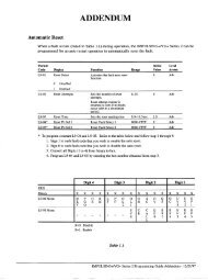
InstallationConnections• The MAC•2000 must be protected against a short circuit by non-semi conductor type (Class CC,600V, 25 Amp) fuse. Input fusing should be sized according to motor FLA.• The starter must be mounted vertically onto a flat, non-flammable panel at least ¼” fromenclosure surface, allowing sufficient space of at least 1 inch above and below the starter forsuitable air flow. Enclosure must be selected to allow surrounding air temperature not to exceed50°C.• Do not mount the starter near heat source.• Protect the starter from dust and corrosive atmosphere.• Connect line voltage to terminal L1, L2, L3.• Connect motor to terminals T1, T2, T3.• Use copper wire with a minimum 75°C temperature rating.• Wire size and type should be determined by local electrical codes.• Low voltage wires shall be wired with class 1 wiring.• When connecting a motor to the output terminals, include a separate ground wire. Attach groundwire solidly to motor frame and to ground terminal.• For single speed motor applications connect a jumper wire to terminals 1 & 2 (see Figure 1:Single speed wiring diagram).• Motor will soft start when FWD/REV contactor closes and will stop when contactor opens.• See Figure 1 for single speed connections or Figure 2 for two speed connections.• For two speed motor applications, connect a voltage free, N.O. contact to terminals 1&2 and3&4 (see Figure 2: Two speed wiring diagram).• External motor overload protection must be provided.NOTE:Connection of voltage to terminals 1 thru 4 will damage the starter.Typical Wire Sizing for Main CircuitModel Number MAC Terminal Symbol Wire Size (AWG) Tightening Torque (lb-in)2024, 2050 L1, L2, L3, T1, T2, T3, GND 16-10 5 to 7Typical Wire Sizing Chart for Control TerminalsTerminal Function1 and 2 Single Speed Enable (see figure 1)3 and 4 Second Speed Enable (see figure 2)MAC•2000 Instruction Manual – 8/1/022
DimensionsFigure 4: DimensionsMAC•2000 Instruction Manual – 8/1/026